| Oracle® Warehouse Builder User's Guide 10g Release 2 (10.2.0.2) Part Number B28223-05 |
|
|
View PDF |
| Oracle® Warehouse Builder User's Guide 10g Release 2 (10.2.0.2) Part Number B28223-05 |
|
|
View PDF |
This chapter describes how to extend the Warehouse Builder repository by creating custom objects and custom properties. This chapter includes the following topics:
As a Warehouse Builder administrator, you may encounter scenarios that require you to add objects or properties to the existing Warehouse Builder repository. Any objects you add to the repository are known as user defined objects (UDOs) and any properties you add are known as user defined properties (UDPs).
For example, as you use Warehouse Builder in conjunction with other applications, you may want to document how the data and metadata you manage in Warehouse Builder interacts with other applications. To facilitate this documentation, you can introduce new metadata objects into the Warehouse Builder repository and associate those objects with existing Warehouse Builder objects. Warehouse Builder displays these custom objects in the Design Center with the icon of your choice, provides a basic editor, and includes the objects in lineage and impact analysis reports.
Administration users can extend the Warehouse Builder repository by adding new properties or by adding new objects.
Adding New Properties to Warehouse Builder Objects: Each Warehouse Builder object has a pre-defined property set to which you can add UDPs. Consider doing this, if, for example, you want to add a property to contain design notes for metadata objects. Once you define them, UDPs behave like native properties.
Adding UDOs to the Repository: You can introduce new objects to the repository by defining UDOs which follow Warehouse Builder rules for object locking, multiuser access, transactions, security, and snapshots. You can also import and export UDOs and UDPs using the Metadata Loader (MDL).
For the sake of clarity, this chapter refers to the objects native to the Warehouse Builder repository as Warehouse Builder objects. Any objects you introduce to the repository are UDOs and any new properties are UDPs.
To define custom objects and properties in Warehouse Builder, you must use the scripting utility Oracle Metabase (OMB) Plus. After you specify the UDOs and UDPs through scripting, you can then create instances of those objects either through scripting or using the graphical user interface (GUI).
OMB Plus is the flexible, high-level command line metadata access tool for Oracle Warehouse Builder. It is an extension of the Tcl programming language and you can use it on UNIX and Windows platforms. With Using OMB Plus Scripts to Specify UDOs and UDPs, you can write the syntactic constructs such as variable support, conditional and looping control structures, error handling, and standard library procedures. Using OMB Plus, you can navigate repositories and manage and manipulate metadata in repositories.
To supplement the information in these sections on using OMB Plus to specify UDOs and UDPs, please refer to the Oracle Warehouse Builder API and Scripting Reference.
OMB Plus scripts enable you to define new objects, add and remove properties, as well as view the attributes for existing objects. The syntax is case sensitive and must be in upper case. When you create UDOs and UDPs, follow the "Naming Conventions for UDOs and UDPs".
OMBDEFINE CLASS_DEFINITION enables you to create new objects in the repository.
To create a new module object, use the following command. This creates a new module called UD_TABLEMODULE:
OMBDEFINE MODULE CLASS_DEFINITION 'UD_TABLEMODULE' SET PROPERTIES (BUSINESS_NAME, PLURAL_NAME) VALUES ('Table Module', 'Table Modules')
OMBREDEFINE CLASS_DEFINITION enables you to redefine Warehouse Builder objects to include custom properties.
To create a UDP on the Dimension object, issue the following statement. This adds a new property called UD_DOCID to class definition DIMENSION:
OMBREDEFINE CLASS_DEFINITION 'DIMENSION'
     ADD PROPERTY_DEFINITION 'UD_DOCID' SET PROPERTIES (TYPE, DEFAULT_VALUE)
     VALUES ('INTEGER', '100')
The following command adds a new property for notes for the COLUMN type. Since columns exist in tables, views, materialized view, external table and sequences, the following command adds the property to columns for all of those metadata objects:
OMBREDEFINE CLASS_DEFINITION 'COLUMN'
     ADD PROPERTY_DEFINITION 'UD_COL_NOTE' SET PROPERTIES (TYPE, DEFAULT_VALUE)
     VALUES ('STRING', 'notes')
When you create and save a new property, OMB Plus performs the following validations:
A user access check ensures that you have single-user access to the entire repository.
A name space check ensures that you did not define two identically named properties within the same class hierarchy.
A property value check ensures that you defined default values consistent with the data types you specified.
To change the name or the default value of a given property, issue a command like the following:
OMBREDEFINE CLASS_DEFINITION 'TABLE' MODIFY PROPERTY_DEFINITION 'UD_TBL_NOTE'
     SET PROPERTIES (DEFAULT_VALUE, BUSINESS_NAME)
     VALUES ('99', 'Table Note')
To delete a UDP, issue a command such as
OMBREDEFINE CLASS_DEFINITION 'TABLE' DELETE PROPERTY_DEFINITION 'UD_TBL_NOTE'
which deletes the UD_TBL_NOTE property from the Table class. Deleting a UDP is a destructive and a highly deprecated action because it cannot be undone. It renders irretrievable all custom property values made for this property definition in your repository.
You can use OMBDESCRIBE on any class definition to view the attributes for a metadata element. Among other tasks, use OMBDESCRIBE to list the UDPs for a given object type. For instance, the following command lists the UDPs for dimensions:
OMBDESCRIBE CLASS_DEFINITION 'DIMENSION' GET PROPERTY_DEFINITIONS
You can also use OMBDESCRIBE to inspect the properties of a property definition. For instance, for a UDP called UD_DOCID, you can know its data type, default value, and business name with the following command:
OMBDESCRIBE CLASS_DEFINITION 'DIMENSION' PROPERTY_DEFINITION  'UD_DOCID'
     GET PROPERTIES (TYPE, DEFAULT_VALUE, BUSINESS_NAME)
It is mandatory to include the prefix UD_ while naming UDOs and UDPs. This ensures that the names of UDOs and UDPs are not identical to the names of predefined objects in the repository.
Note:
UDPs named with the prefix UDP_ are still valid. However, with the current release, it is preferred to use the prefix UD_ while naming UDOs as well as UDPs.To define new properties on Warehouse Builder objects, complete the following steps:
Carefully plan the new additions to the repository.
If possible, you should define all user-defined properties into the Warehouse Builder repository before allowing end users to access it. In doing so, you avoid the task of supplying values for UDPs on existing objects.
Log in to Warehouse Builder as the repository owner and in single user mode.
If another user is logged on through the GUI or OMB Plus, Warehouse Builder prevents you from running commands that alter the structure of the repository.
If already logged into the Warehouse Builder Design Center, you can launch OMB Plus from Window on the main menu. To ensure that no other users access the repository, connect to the repository and issue the command OMBSWITCHMODE SINGLE_USER_MODE.
Use the command OMBREDEFINE on the Warehouse Builder object you want to add a custom property.
For examples on how to use this command, see the section OMBREDEFINE.
To view the changes in OMB Plus, use the command OMBDESCRIBE.
Once you create the UDP using scripting, users can view and assign values to the new property in the GUI.
Notify users that they can log in to Warehouse Builder.
Complete the following steps to create UDPs for an object:
Log in to the Warehouse Builder client as an administrator.
Open the OMB Plus client.
Ensure that you are in the single user mode. You can verify this with the command OMBDISPLAYCURRENTMODE. If you are in multiple user mode, switch to single user mode by using the command.
OMBSWITCHMODE SINGLE_USER_MODE
In the OMB Plus client, type the following to create four UDPs for the object View:
OMBREDEFINE CLASS_DEFINITION 'VIEW' \
ADD PROPERTY_DEFINITION 'UDP_OWNER' SET PROPERTIES \
(TYPE, DEFAULT_VALUE, BUSINESS_NAME) VALUES \
('STRING', 'REP_OWNER', 'Object Owner')
OMBREDEFINE CLASS_DEFINITION 'VIEW' \
ADD PROPERTY_DEFINITION 'UDP_FILE' SET PROPERTIES \
(TYPE, DEFAULT_VALUE) VALUES ('FILE', 'C:\\vw.sql')
OMBREDEFINE CLASS_DEFINITION 'VIEW' \
ADD PROPERTY_DEFINITION 'UDP_LINK' SET PROPERTIES \
(TYPE, DEFAULT_VALUE) VALUES ('URL', 'http://www.oracle.com')
OMBREDEFINE CLASS_DEFINITION 'VIEW' \
ADD PROPERTY_DEFINITION 'UDP_VERSION' SET PROPERTIES \
(TYPE, DEFAULT_VALUE) VALUES ('DATE', '2006-1-7')
OMBSAVE
This creates the following UDPs: UDP_OWNER, UDP_FILE, UDP_LINK, and UDP_VERSION.
Note:
The valid UDP types are integer, string, float, double, date, timestamp, boolean, long, file, and url.From the Project Explorer create a view in any module.
Open the property inspector for the view by right-clicking the view and selecting Properties.
Click the User Defined tab and select the view in the left-hand panel. The newly created UDPs are visible as shown in Figure 34-1.
Note:
You can modify the values of any of the UDPs from the GUI.To remove a UDP from the repository, use the DELETE clause. For example, to delete UDP_VERSION, use the following command:
OMBREDEFINE CLASS_DEFINITION 'VIEW' DELETE PROPERTY_DEFINITION 'UDP_VERSION'
UDOs are objects that you define and add to the repository in addition to existing Warehouse Builder objects.
A UDO consists of a primary object called the module. This module acts as the topmost container holding other objects within. A module can contain folders, first class objects (FCOs), and second class objects (SCOs). Similarly, a folder can contain other folders, FCOs, and SCOs, while an FCO can contain one or more SCOs.
The objects in a UDO exhibit a parent-child relationship. The module is the parent. An FCO within a module is a child element of the module. Similarly, an SCO within an FCO is a child element of the FCO. For example, an Oracle module in the Warehouse Builder is a parent module. A table within this module is an FCO and a column within the table is an SCO.
To define new objects for the repository, complete the following steps:
Carefully plan the new additions to the repository.
Before you begin, fully review the remainder of this chapter and become familiar with the necessary scripting commands.
Log in to Warehouse Builder as an administrator and in single user mode.
Design the UDO based on the steps described in "Writing Scripts to Define UDOs".
Use the OMBDEFINE command to create a new module, and FCOs and SCOs within that module. Use the OMBREDEFINE command to set the properties for these objects.
Once you create the UDO using scripting, you can use the GUI to create and edit the objects it contains.
Log in to the Warehouse Builder GUI and view the new objects as described in "Working with UDOs and UDPs".
Verify that the new objects display as intended.
(Optional) Assign a new icon to the user defined object as described in"Creating New Icons for Objects in Warehouse Builder".
Notify users that they can log in to Warehouse Builder.
To define a UDO, write a script that completes the following steps:
Create a user defined module: This will be the parent module.
Define the object type: Define the module as a folder that can contain other objects.
Define FCOs and SCOs: Create FCOs and SCOs for the UDO, and assign physical names to these objects. For example, UD_WORKBOOK is a valid physical name. You can also indicate a business name and plural name, both of which Warehouse Builder displays in the Design Center and in editors. Continuing the previous example, Workbook and Workbooks are likely entries for the business name and plural name respectively. If you do not specify these values, Warehouse Builder defaults to the physical name.
Define object properties: Set the properties for all the objects you create. Some properties, such as Name, Business_Name, Plural_Name, and Description, are assigned automatically to any newly created object.
Add component definition: All parent objects need to be assigned a component definition. The child elements have to be added to the component definition. The component definition determines the lifetime of child elements. For example, a column cannot exist if the parent table is deleted.
Define association types: Create association types to indicate the types of relationships a UDO can have with Warehouse Builder objects and other UDOs. You need to perform this step only if you want end users to later relate the UDO to specific instances of objects. For instance, in your script you could associate the UDO with tables and views. In the Design Center, end users could then relate instances of the UDO with specific tables and views. Warehouse Builder displays these relationships in impact and lineage analysis reports.
Assign icons (optional)
Save the changes
This section provides an example to create an UDO that is modeled on a Java application. The application is a module. This module contains classes (FCOs) and those classes contain methods (SCOs). Within a method, you can model the lines of code. From a business standpoint, this is of interest because a particular line of code in an application may be impacted by a change in a database table if it is used within a SQL (JDBC) statement. The structure of the UDO is as shown in Figure 34-2.
To create the UDO, perform the following steps:
Log in to the Warehouse Builder client as an administrator and open the OMB Plus window. Make sure that you are logged in the single user mode.
First create a module class and set properties for this module:
OMBDEFINE MODULE CLASS_DEFINITION 'UD_JAVA_APP' \
SET PROPERTIES (BUSINESS_NAME, PLURAL_NAME) \
VALUES ('Java Application', 'Java Applications')
This defines the class and sets certain properties that all Warehouse Builder objects have. BUSINESS_NAME is the user-friendly name for an object. If the Naming mode preference for the Design Center is switched into Business mode, then the value set for BUSINESS_NAME is displayed for the object. PLURAL_NAME is the label that is used to show where multiple instances of an object are shown, such as the label used for a tree node in the Design Center that contains several instances of the object.
Now create a folder with the same name as the module so that the module assumes the role of a folder:
OMBDEFINE FOLDER_DEFINITION 'UD_JAVA_APP'
Now create an FCO:
OMBDEFINE FIRST_CLASS_OBJECT CLASS_DEFINITION \
'UD_JCLASS' SET PROPERTIES (BUSINESS_NAME, PLURAL_NAME) \
VALUES ('Java Class File', 'Java Class Files')
Add the FCO as a child of the folder class:
OMBREDEFINE CLASS_DEFINITION 'UD_JAVA_APP' \
ADD CHILD_TYPE 'UD_JCLASS'
Create a component definition for the FCO:
OMBDEFINE COMPONENT_DEFINITION 'UD_JCLASS'
Add the component definition to the folder definition:
OMBREDEFINE FOLDER_DEFINITION 'UD_JAVA_APP' \
ADD 'UD_JCLASS'
Create an SCO and set its properties:
OMBDEFINE SECOND_CLASS_OBJECT \
CLASS_DEFINITION 'UD_JMETHOD' \
SET PROPERTIES (BUSINESS_NAME, PLURAL_NAME) \
VALUES ('Method', 'Methods')
Add the SCO as a child of the FCO:
OMBREDEFINE CLASS_DEFINITION 'UD_JCLASS' \
ADD CHILD_TYPE 'UD_JMETHOD'
Add the SCO to the component definition:
OMBREDEFINE COMPONENT_DEFINITION 'UD_JCLASS' \
ADD 'UD_JMETHOD'
Create an SCO and set its properties:
OMBDEFINE SECOND_CLASS_OBJECT \
CLASS_DEFINITION 'UD_JMETHOD_LINE' \
SET PROPERTIES (BUSINESS_NAME, PLURAL_NAME) \
VALUES ('Java Method Line', 'Java Method Lines')
Add this SCO as a child of the initially created SCO:
OMBREDEFINE CLASS_DEFINITION 'UD_JMETHOD' \
ADD CHILD_TYPE 'UD_JMETHOD_LINE'
Add this SCO to the component definition:
OMBREDEFINE COMPONENT_DEFINITION 'UD_JCLASS' \
ADD 'UD_JMETHOD_LINE'
This creates an UDO with the following characteristics:
A module folder called UD_JAVA_APP
An FCO, UD_JCLASS, within the module
An SCO, UD_JMETHOD, which is the child of UD_JCLASS
An SCO, UD_JMETHOD_LINE, which is the child of UD_JMETHOD
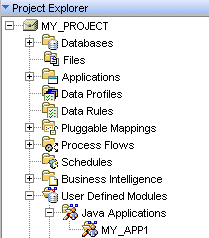
You can access the UDO from the Project Explorer under the User Defined Modules icon as shown in Figure 34-3. To create a new instance of the UDO, right-click the UDO and select New. You can create new modules and SCOs as well as edit these modules and SCOs.
Note:
For the newly created UDO to be visible in the Project Explorer, you must shut down Warehouse Builder completely, and then start it up again, saving any changes if prompted.Figure 34-3 Accessing UDO from the Project Explorer
UDOs can be associated with other objects. By creating these associations, you can use UDOs just like any other object when doing Lineage and Impact Analysis.
Associating a Java Application with a Table
This example associates the SCO, UD_JMETHOD, with one or more tables. This is modeling the fact that a method could be referencing tables in JDBC calls.
To associate the Java method to table, use the command:
OMBDEFINE ASSOCIATION_DEFINITION 'UD_XJMETHOD2TABLE' \
SET PROPERTIES (CLASS_1,CLASS_2,ROLE_1,ROLE_2 \
,ROLE_1_MAX_CARDINALITY,ROLE_1_NAVIGABLE) \
VALUES ('UD_JMETHOD','TABLE','TABLEUSED','JM2TABLE' \
,'INFINITE','true') ADD DEPENDENCY_DEFINITION 'DATAFLOW'
CLASS_1 and CLASS_2 can be any classes (FCO or SCO). At least one of the classes should be a user defined class. The other class can be either a user defined class or one of the main Warehouse Builder classes, such as table or column. In this example, the association is between the UDO, UD_JMETHOD, and table.
Role_1 and Role_2 are the names you use to identify Class_1 from the point of view of this association. A class may have multiple associations and it plays a role in each one of them.
MAX_CARDINALITY enables you to limit the number of objects of that class which participate in that association. For example, consider the association between uniqueKey and foreignKey. The max_cardinality of uniqueKey is 1, because a given foreignKey object can be associated with at most one uniqueKey object. MAX_CARDINALITY can be set to any positive integer, or the reserved word INFINITE.
ROLE_1_NAVIGABLE is used by Lineage/Impact analyzer. If set to TRUE, it means that the analyzer can traverse the association in either direction between Class_1 and Class_2. If the property is set to FALSE, it means that the analyzer can traverse the relationship from Class_1 to Class_2, but not the other way around.
DEPENDENCY_DEFINITION is a mandatory parameter of an association and must always be set to DATAFLOW.
To associate the UDO to a table, complete the following steps:
In the Project Explorer, expand the node User Defined Modules.
Right-click Java Applications and select New.
Specify a name for the application.
Right-click the node Java Class Files and select New.
Specify a name for the Java class.
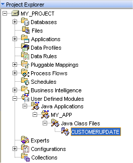
Right-click the object you just created, and select Open Editor to open the UDO Editor.
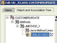
Click the Object and Association Tree tab and select CUSTOMERUPDATE. You can see the properties for the FCO, UD_JCLASS, as shown in Figure 34-4.
Right-click Methods and select Create.
An SCO called JMETHOD_1 is created.
JMETHOD_1 contains two nodes: Java Method Lines, which is the child SCO, and TABLEUSED, which is the value specified for ROLE_1 when the association UD_XJMETHOD2TABLE was created.
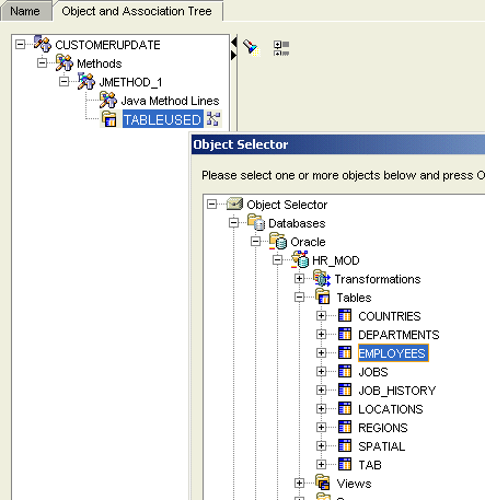
Right-click TABLEUSED and select Reference.
The Object Selector dialog appears, and enables you to select the table to which you want to connect the UDO.
In the GUI, you can view UDOs and UPDs in the Project Explorer and in the Warehouse Builder Design Browser. However, in the Project Explorer, you can also edit the UDOs and UDPs.
Warehouse Builder Design Browser
Warehouse Builder Browser is a metadata management and reporting portal for Warehouse Builder. This browser displays objects, object properties, object relationships, including UDOs and UDPs. The browser also displays lineage and impact analysis reports for all objects including UDOs.
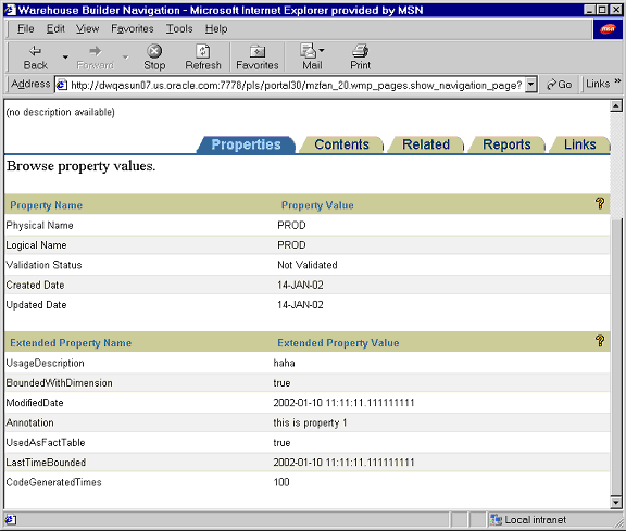
If you define a UDP for a given object, the browser lists the UDP name and values as Extended Property Name and Extended Property Value as shown in Figure 34-5.
Figure 34-5 Sample Properties Sheet with User-Defined Properties
The primary method for propagating changes from one repository to another is using MDL. The MDL enables you to export and import the metadata definition of the UDP and its contents.
You can export UDOs and UDPs as any other object.
In the MDL Control file, the option is DEFINITIONFILE=filename to export the metadata definition. For example:
## Sample Export file
USERID=UserName/Password@HostName:PortID:OracleServiceName
#
DEFINITIONFILE=Drive:\DirectoryName\filename.mdd

FILE=Drive:\DirectoryName\filename.mdl
LOG=Drive:\DirectoryName\filename.log
You can import UDPs from the command line only. During import, MDL updates the UDPs for all objects. In the MDL Control file, the option is DEFINITIONFILE=filename to import the metadata definition. For example:
## Sample Import file
USERID=UserName/Password@HostName:PortID:OracleServiceName
#
DEFINITIONFILE=Drive:\DirectoryName\filename.mdd

FILE=Drive:\DirectoryName\filename.mdl
LOG=Drive:\DirectoryName\filename.log
You can import UDPs using one of the following search criteria:
Universal ID: The metadata definition contains a Universal Object ID (UOID). The UOID uniquely identifies objects across repositories. If you import the MDL file by UOID, then MDL looks up the metadata definition by UOID. If the metadata definition name in the source MDL file is different from the metadata definition in the repository, then MDL renames it.
Physical Name: MDL looks up the metadata definition by physical name.
Regardless of the import mode, MDL either adds the metadata definition if it does not exist in the repository, or updates the metadata definition if it already exists. MDL will not delete metadata definitions in the repository.
When updating the metadata definition, MDL only renames the object if the names are different (search criteria is by UOID), and updates the default value. MDL does not change the data type.
Icons are graphics that visually suggest the availability of a function or type of an object to end users. There are many types of objects pre-defined inside Warehouse Builder, each with their own icon. You may want to change the icon associated with an existing object or instance of an object to something more recognizable. For example, you could visually highlight a particular table by altering its icon. Additionally, for UDOs, you may want to change the default icon to something representative of the object. You can create your own icons using a graphics editor or third party software.
In the Design Center, you can associate icon sets with an instance of an object. Or, use the OMB Plus scripting language to associate icon sets at the object type level (and thus inherited by any instance of that object).
Note:
You can assign new icons to most Warehouse Builder objects with the exception of pre-defined objects like public transformations and public data rules and DEFAULT_CONFIGURATION, DEFAULT_CONTROL_CENTER, and OWB_REPOSITORY_LOCATION.Every object in Warehouse Builder has a set of icons of varying sizes to represent it throughout the various editors and toolbars. Each icon set includes a canvas icon, palette icon, and a tree icon as described in Table 34-1. When you define a new icon set, follow the sizing guidelines. If you specify a new icon with an incorrect size, Warehouse Builder automatically resizes it, which may distort your intended design.
Table 34-1 Icon Sets
| Type | Description |
|---|---|
|
Canvas Icon |
Represents instances of objects in the canvas of an editor. For example, it displays a table icon in the canvas of the Mapping Editor or in a Lineage Report. The correct size is 32 x 32 pixels in GIF or JPEG format |
|
Palette Icon |
Represents types of objects in editor palettes. For example, it displays the table operator in the Mapping Editor operator palette. The correct size is 18 x 18 pixels in GIF or JPEG format |
|
Tree Icon |
Represents types and instances of objects in navigation trees such as the Project Explorer in the Design Center. The correct size is 16 x 16 pixels in GIF or JPEG format |
To create a new icon set, complete the following steps:
Log in to the Warehouse Builder client as an administrator.
In the Global Explorer, right-click the Icon Sets node and select New.
The Create Icon Set dialog is displayed. For details on the values to be entered on this page, see "Create Icon Set Dialog" .
The Create Icon Set dialog enables you to specify values for the Icon Set. Enter the following values and click OK to define a new Icon Set:
Name: The name of the Icon Set.
Group: You can assign the Icon Set to any of the groups available in the list. This is useful when you are creating a large number of icon sets and want to organize them into different groups.
Description: A description of the Icon Set.
File Name: Navigate and select the image that you want to assign to the new Icon Set. You need to select an image for Canvas, Palette, and Tree Icon.
Note:
You can use any image of your choice to represent the new icon.The newly created icon set will be available under Icon Sets in the Global Explorer as shown in Figure 34-6.
You can change the default icon setting for any object in Warehouse Builder by editing its properties. In any of the Explorers in the Design Center, right-click an object and select Properties to assign a new icon set to an object. When you save your changes, Warehouse Builder displays the new icon set throughout the user interface.
To revert back to the original icon, select Use Product Default Icon.
For more information on icon sets, see "Creating New Icons for Objects in Warehouse Builder" .
Complete the following steps to assign a newly created icon set, CSV_ICONSET, to an instance of an object.
Right click any instance of an object and select Properties to open the Property Inspector.
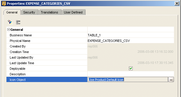
On the General tab, click the field Use Product Default Icon.
An Ellipsis button is displayed in this field as shown in Figure 34-7.
Figure 34-7 Properties Inspector for EXPENSE_CATEGORIES_CSV
Click the Ellipsis button to open the Icon Object dialog.
Select CSV_ICONSET and click OK.
CSV_ICONSET is now assigned to the instance EXPENSE_CATEGORIES_CSV as shown in Figure 34-8.
Figure 34-8 Icon Set for EXPENSE_CATEGORIES_CSV
You can assign new icon sets to the activities in a process flow. The Process Flow Editor contains the Select Icon button, which gets enabled when you select an activity, as shown in Figure 34-9.
Figure 34-9 The Select Icon button on the Process Flow Editor
To assign a new icon set to an activity:
Select the activity and click the Select Icon button. The Select Icon Set dialog displays.
Select an icon from the list and click Select.
The icon set is assigned to the activity.
For information on process flows, see Chapter 7, "Designing Process Flows".
You can assign new icon sets to the tasks in Expert Editor using the Select Icon button available on the Expert Editor. This is similar to assigning icon sets to activities in a process flow.
To assign a new icon set to a task:
Select the task and click the Select Icon button. The Select Icon Set dialog displays.
Select an icon from the list and click Select.
The icon set is assigned to the task.
For information on experts, see Oracle Warehouse Builder API and Scripting Reference.