| Oracle® Enterprise Service Bus Developer's Guide 10g (10.1.3.3.0) Part Number E10295-01 |
|
|
View PDF |
| Oracle® Enterprise Service Bus Developer's Guide 10g (10.1.3.3.0) Part Number E10295-01 |
|
|
View PDF |
This chapter describes features of the XSLT Data Mapper and provides instructions for using a transformation mapping in routing rules.
This chapter contains the following topics:
The Data Mapper tool provides data transformation in the routing rules of the routing service. You use the XSLT Mapper transformation tool to create the contents of a map file. Figure 6-1 shows the layout of the XSLT Mapper.
The Source and the Target schemas are represented as trees and the nodes in the trees are represented using a variety of icons. The displayed icon reflects the schema or property of the node. For example:
An XSD attribute is denoted with an icon that is different from an XSD element
An optional element is represented with an icon that is different from a mandatory element
A repeating element is represented with an icon that is different from a nonrepeating element, and so on
The various properties of the element and attribute are displayed in the Property Inspector in the lower right of Figure 6-1 (for example, type, cardinality, and so on). The Functions Palette in the upper right of Figure 6-1 is the container for all functions provided by the XSLT Mapper. The mapper pane or canvas is the actual drawing area for dropping functions and connecting them to source and target nodes.
The XSLT Mapper provides three separate context sensitive menus:
One in the source panel
One in the target panel
One in the mapper pane or canvas in the middle
Right-click in each of the three separate panels to see what the context menus look like. A full set of Undo Auto Map, Redo, Delete, and Delete All functions are also available.
A node in the target tree can be linked only once (that is, you cannot have two links connecting a node in the target tree).
An incomplete function and expression does not result in an XPath expression in the source view. If you switch from the design view to the source view with one or more incomplete expressions, the Mapper Messages window displays warning messages.
When you map duplicate elements in the XSLT Mapper, the style sheet becomes invalid and you cannot work in the Design view. The Log Window shows the following error messages when you map an element with a duplicate name:
Error: This Node is Already Mapped  :
"/ns0:rulebase/for-each/ns0:if/ns0:atom/ns0:rel"
  Error: This Node is Already Mapped  :
"/ns0:rulebase/for-each/ns0:if/ns0:atom/choice_1/ns0:ind"
  Error: This Node is Already Mapped  :
"/ns0:rulebase/for-each/ns0:if/ns0:atom/choice_1/ns0:var"
The workaround is to give each element a unique name.
The XSLT Data Mapper tool that enables you to create an xsl file to transform data from one XML schema to another. After you define an xsl file, you can reuse it in multiple routing rule specifications. This section provides an overview of creating a transformation map xsl file with the XSLT Data Mapper tool.
The Data Mapper tool is available through the Routing Service property page or from the routing service icon in the Design tab of Oracle JDeveloper. You can either create a new transformation map or update an existing one.
To launch the Data Mapper tool from Routing Service property page and create or update a data transformation xsl file, follow these steps:
Open the properties page of a Routing Service.
Open the Routing Rules panel by clicking on the + to the left of Routing Rules as described in "Specifying Routing Rules".
The transformation map icon is visible in the routing rules panel. For an example of the routing service property page with the transformation map icon in the routing rules panel, see Figure 5-8.
Click the transformation map icon to the right of the Transformation Map field in the routing rules panel to open the Request Transformation Map dialog, shown in Figure 5-17.
The Request Transformation Map dialog displays with options for selecting an existing transformation map (XSL) file or creating a new map file.
Figure 6-2 Request Transformation Map Dialog
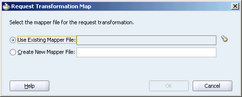
If the routing rule includes a reply or fault, the Request Transformation Map dialog contains the Include Request in the Reply Payload option for reply or fault transformations. When you enable this option, you can obtain information from the request message. When you create a new map for reply or fault transformations, the ESBREQUEST variable is added on the source side of the Data Mapper tool. When you view the properties in the Edit Parameter dialog for ESBREQUEST, you can add XPath Expression functions.
Choose one of the following options:
Create New Mapper File and then enter a name for the file (or accept the default value).
Use Existing Mapper File and then click the flashlight icon to browse for an existing mapper file (or accept the default value). When the data mapper tool opens, you can update the existing file.
Click OK.
If you chose Create New Mapper File, the XSLT Data Mapper tool opens to enable you to correlate source schema elements to target schema elements, as shown in Figure 6-1.
You can select and drag a component on either side of the tool to the component you want to correlate on the other side of the mapper tool. When you initially select and drag, the Auto Map Preferences dialog displays so you can set preferences for the mapping.
You can choose to drag and drop source elements to target elements individually or you can use the AutoMap feature in the Auto Map Preferences dialog. If you enable the AutoMap and Match Elements with Similar Names options, the Data Mapper tool automatically maps source elements to target elements after you click OK in the Auto Map Preferences dialog, as shown inFigure 6-4.
You can edit a new or existing transformation map.
Add new links by dragging and dropping source elements to target elements.
Remove (undo) links by selecting the link and right-clicking to bring up menu options. Select Undo link from the context menu.
After you have completed the transformation map, use File > Save to save the xsl file.
You can directly launch the Data Mapper tool by double-clicking on a data transformation icon in a routing service icon in the Design tab. If the transformation exists, the Data Mapper tool opens for you to update the transformation file. If the transformation file has not been specified yet, the Request Transformation Map dialog displays and enables you to create a new transformation file or select an existing transformation map file for update.
Note:
You can also create an XSL transformation map file from an XSL stylesheet. Click New, then XML, then XSL Map From XSL Stylesheet from the File main menu in Oracle JDeveloper.Note:
If you select a file with anxslt extension such as xform.xslt, it opens the mapper pane to create a new XSL file named xform.xslt.xsl, even though your intension was to use the existing xform.xslt file. An xsl extension is appended to any file that does not already have an xsl extension, and you must create the mappings in the new file. As a workaround, ensure that your files first have an extension of xsl. If the XSL file has an extension of xslt, then rename it to xsl.The following sections describe how to use the XSLT Mapper:
To copy an attribute or leaf-element in the source to an attribute or leaf-element in the target, drag and drop the source to the target, as shown in Figure 6-6.
Perform the following steps to set a constant value.
Select a node in the target tree.
Invoke the context menu by right-clicking the mouse.
Select the Set Text menu option.
Enter text in the Set Text window.
Click OK to save the text.
A T icon is displayed next to the node that has text associated with it.
If you want to remove the text associated with the node, right click the node to invoke the Set Text window again. Delete the contents and click OK.
See Also:
The online Help for the Set Text window for detailed informationIn addition to the standard XPath 1.0 functions, the Data Mapper provides a number of prebuilt extension functions and has the ability to support user-defined functions and named templates. The extension functions are prefixed with xp20 or orcl and mimic XPath 2.0 functions.
To view function definitions and use a function in a data transformation map, Perform the following steps:
Select a category of functions, such as String Functions, from the Component Palette.
Right-click an individual function, such as lower-case.
Select Help. A window with a description of the function appears. You can also click a link at the bottom to access the function description at the World Wide Web Consortium at www.w3.org.
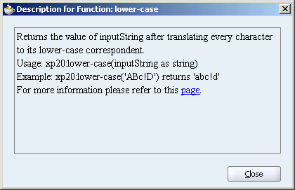
Drag a function from one of the functions categories in the Component Palette to the data mapper pane.
You can drag a function from the Component Palette on an existing link in the mapper pane.
For example, drag the lower-case function under String Functions on an existing link into the mapper pane, such as Email in the source list to contactemail in the target list. This function converts the email value in the source element to lower case when it is output to the target element.
You can drag a function into an empty area of the mapper pane. Then drag a source elements on the left handle of the function and a target element on the right handle of the function.
For example, drag the concat function under String Functions to the mapper pane. Drag threads from multiple source elements, such as CustomerData/ContactTitle and CustomerData/ContactName, to the left handle of the concat function. Then drag a thread from the Customer/ShippingAddress/Title element in the target list. This function combines the values in the source elements when it is output to the target element.
When you have finished adding functions, use File > Save to save the changes to the data transformation xsl file.
See Also:
Appendix A, "XPath Extension Functions" for reference information about the XPath extension functions.
To edit the parameters of a function in the data mapper pane, double-click the function icon to launch the Edit Function dialog. This window enables you to add, remove, and reorder parameters.
For example, to edit the parameters of the concat function, double-click the function icon to launch the Edit Function - concat window. If you want to add a new parameter so that the output of the concat function is ContactTitle: Contact Name, then click Add to add a new parameter ':' (with single quotes) and reorder the parameters to get this output.
See Also:
The online Help for the Edit Function window by clicking the Help button to see how to add, remove, and reorder function parametersComplex expressions can be built by chaining functions. The chaining function can also be defined by dragging and dropping the function to a connecting link.
For example, to remove all leading and trailing spaces from the output of the concat function discussed in "Editing Function Parameters", use the left-trim and right-trim functions and chain them as shown in the Figure 6-10.
Some complicated mapping logic cannot be represented or achieved by visual mappings. For these situations, named templates are useful. Named templates enable you to share common mapping logic. You can define the common mapping logic as a named template and then use it as often as you want.
You define named templates in the source view, and they appear in the User Defined Named Templates list of the Component Palette. You can use named templates in almost the same way as you use other functions. The only difference is that you cannot link the output of a named template to a function or another named template; you can only link its output to a target node in the target tree.
To write named templates, you must be familiar with the XSLT language. See any XSLT book or visit the following URL for details about writing named templates:
http://www.w3.org/TR/xslt
You can import your own set of Java functions, which appear in the function palette under the User defined Extension Functions category. They can be used like any other function. To add functions, select Preferences, then XSL Maps from the Tools main menu.
In the XSLT mapper source view, you can use the user-defined functions in the following way:
NamespacePrefix:FunctionName([ARGUMENT1, ARGUMENT2, ARGUMENT3...])
The namespace prefix should be declared in the XSL file as follows:
"http://www.oracle.com/XSL/Transform/java/<ClassNameincludingthePackageName>"
To use an XPath expression in a transformation mapping, select Advanced Functions from the Component Palette and drag and drop xpath-expression from the list into the data mapper transformation pane.
When you double-click the icon, the Edit XPath Expression dialog appears. You can press the Ctrl + spacebar to invoke the XPath Building Assistant, as show in Figure 6-11.
See Also:
The online Help for the Edit XPath Expression window, which includes a link to instructions on using the XPath Building AssistantWhile mapping complex schemas, it is sometimes essential to conditionally map a source node to a target or map an array of elements in the source to an array of elements in the target. The XSLT Mapper provides various XSLT constructs in the context sensitive menu of the target tree for the these conditional scenarios. These constructs include for-each, if, or choose.
To add an XSLT element such as for-each, if, or choose to a schema element:
Select the element in the target tree.
Right-click and select Add XSL Node to bring up the context menu.
Choose the required XSLT element in the menu.
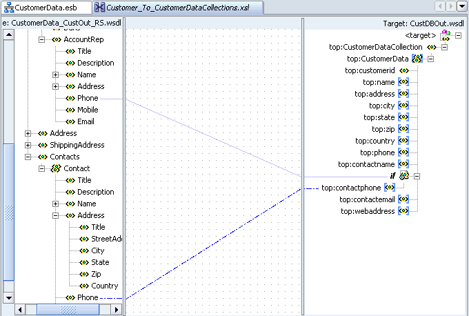
With the if construct, you can choose to map a source element if a the value exists and map a value from a different element when it does not exist. For example, if the source contains an AccountRep phone number use that value. If the AccountRep phone number does not exist, then use the Contact phone number.
Select the target element in the target tree and right-click to bring up the context sensitive menu.
Select Add XSL Node, and then if.
Connect a source element to the if element in the target tree.
Connect a source element to the target element.
Figure 6-12 shows the results.
Figure 6-12 Conditional Processing with xsl:if
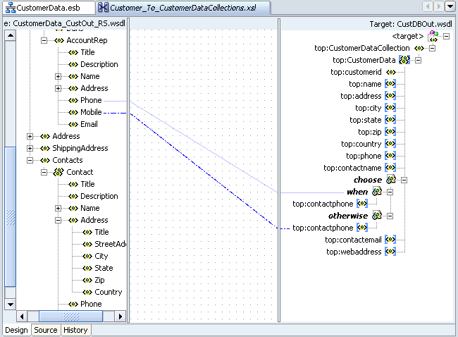
With the choose construct, you can copy a source element to a specified target element, if the source element exists. Otherwise, copy a different source element to the target element.
Select the target element in the target tree and right-click to bring up the context sensitive menu.
Select Add XSL Node, and then choose.
Connect the source element to the target element to define the condition.
Select choose in the target tree and right-click to bring up the context sensitive menu.
Select XSL Add Node and then otherwise.
Connect the source element to the target element under otherwise.
Figure 6-13 shows the results.
Figure 6-13 Conditional Processing with xsl:choose
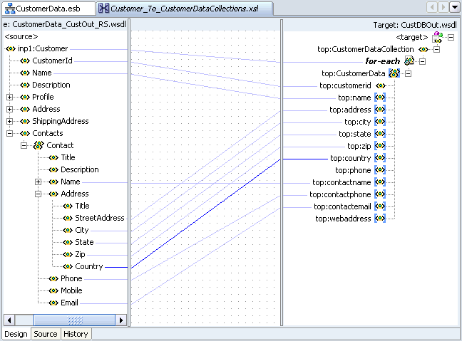
The XSLT Mapper allows repeating elements on the source to be copied to repeating elements on the target.
Select a target element in the target tree and right-click to bring up the context sensitive menu.
Select Add XSL Node, and then for-each.
Connect the repeating source elements to the targets elements.
Figure 6-14 shows the results.
Figure 6-14 Handling Repetition or Arrays
Note:
Executing an auto map automatically inserts xsl:for-each.Mapping nonleaf nodes starts the auto map feature. The system automatically tries to link all relevant nodes under the selected source and target, as shown in Figure 6-4.
The behavior of the auto map can be tuned by altering the settings in Oracle JDeveloper preferences or by right-clicking the transformation window and selecting Auto Map Preferences. This displays the window shown in Figure 6-3.
This window enables you to customize your auto mapping as follows:
Invoke the automatic mapping feature, which attempts to automatically link all relevant nodes under the selected source and target. When disabled, you must individually map relevant nodes.
Display and review all potential source-to-target mappings detected by the XSLT Mapper, and then confirm to create them.
Be prompted to customize the auto map preferences before the auto map is invoked.
Select the Basic or Advanced method for automatically mapping source and target nodes. This enables you to customize how the XSLT mapper attempts to automatically link all relevant nodes under the selected source and target.
Manage your dictionaries. The XSLT Mapper uses the rules defined in a dictionary when attempting to automatically map source and target elements.
See Also:
The online Help for the Auto Map Preferences window by clicking the Help button to see a description of the fieldsTo see potential source mapping candidates for a target node, right-click the target node, select Show Matches, and click OK in the Auto Map Preferences window. The Auto Map window appears, as shown in Figure 6-15.
See Also:
The online Help for the Auto Map window by clicking the Help button to see a description of the fields.When the Confirm Auto Map Results check box shown in Figure 6-3 is selected, a confirmation window appears. If matches are found, the potential source-to-target mappings detected by the XSLT Mapper are displayed, as shown in Figure 6-16. The window enables you to filter one or more mappings.
See Also:
The online Help for the Auto Map window by clicking the Help button to see a description of the fieldsYou can view a list of target nodes that are currently unmapped to source nodes. Right click in the mapper pane as shown in Figure 6-5 and select Completion Status. This window provides statistics at the bottom about the number of unmapped target nodes. This window enables you to identify and correct any unmapped nodes before you test your transformation mapping logic on the Test XSL Map window. Select a target node in the list. The node is highlighted. A check mark indicates that the target node is required to be mapped. If not required, the check box is empty.
Figure 6-17 provides an example of the Completion Status window.
A dictionary is an XML file that captures the synonyms for mappings. Right-click in the mapper pane as shown in Figure 6-5 and select Generate Dictionary. This prompts you for the dictionary name and the directory in which to place the dictionary.
The XSLT Data Mapper uses the rules defined in the dictionary when attempting to automatically map source and target elements. For example, you may want to map a purchase order to a purchase order acknowledgment, then reuse most of the map definitions later.
Build all the mapping logic for the purchase order and purchase order acknowledgment.
Generate a dictionary for the created map.
Create a new map using a different purchase order and purchase order acknowledgment.
Load the previously created dictionary by selecting Tools > Preferences > XSL Maps > Auto Map in Oracle JDeveloper.
Perform an automatic mapping from the purchase order to the purchase order acknowledgment.
You can create map parameters and variables. You create map parameters in the source tree and map variables in the target tree.
Note the following issues:
Parameters are created in the source tree, are global, and can be used anywhere in the mappings.
Variables are created in the target tree, and are either global or local. Where they are defined in the target tree determines if they are global or local.
Global variables are defined immediately below the <target> node and immediately above the actual target schema (for example, POAcknowledge). Right-click the <target> node to create a global variable.
Local variables are defined on a specific node below the actual target schema (for example, subnode name on schema POAcknowledge). Local variables can have the same name as long as they are in different scopes. Local variables can only be used in their scopes, while global variables can be used anywhere in the mappings.
Right-click the source tree root and select Add Parameter.
The Create Parameter window appears.
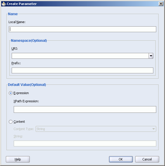
Specify the information for the parameter.
Click OK.
Right-click the target tree root and select Add Variable. If you right-click a node below the target tree root, select Insert Variable.
The Create Variable window appears.
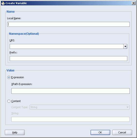
Specify the information for the variable.
Click OK.
You can search source and target nodes. For example, you can search in a source node named Customer for all occurrences of the subnode named Name.
To search for a source or target node:
Right-click a source or target node.
Select the Find menu item.
The Find Node dialog displays.
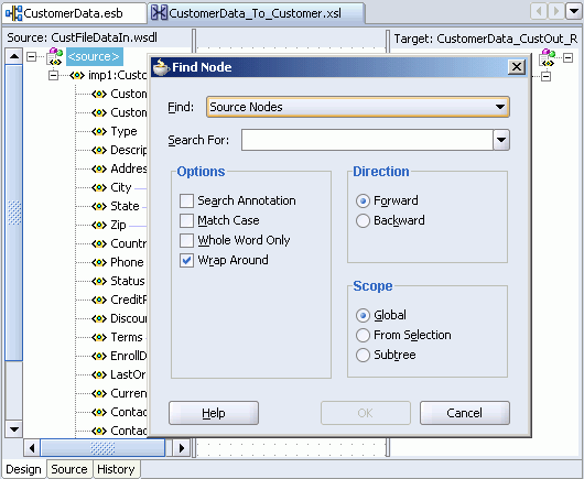
In the Search For field, enter a keyword to search on.
Specify additional details, as necessary. For example:
Select Search Annotations if you want annotations text to also be searched.
Specify the scope of the search. You can search the entire source or target tree, search starting from a selected position, or search within a selected subtree.
The first match found is highlighted, and the Find window closes. If no matches are found, a message displays on-screen.
Select the F3 key to find the next match in the direction specified. To search in the opposite direction, select the Shift and F3 keys.
Note:
You cannot search on functions or text values set with the Set Text option.When the XSLT Mapper encounters any elements in the XSLT document that cannot be found in the source or target schema, it is unable to process them and displays an Invalid Source Node Path error. XSL map generation fails. You can create and import a file that directs the XSLT Mapper to ignore and preserve these specific elements during XSLT parsing by selecting Preferences, then XSL Maps in the Tools main menu of Oracle JDeveloper.
For example, preprocessing may create elements named myElement and myOtherElementWithNS that you want the XSLT Mapper to ignore when it creates the graphical representation of the XSLT document. You create and import a file with these elements to ignore that includes the following syntax:
<elements-to-ignore>
   <element name="myElement"/>
   <element name="myOtherElementWithNS" namespace="NS"/>
</elements-to-ignore>
You must restart Oracle JDeveloper after importing the file.
You can replace the map source schema and map target schema that currently display in the XSLT Mapper. Right click in either the source or target panel and select Replace Schema. This opens the Select Source and Target Schema window, which enables you to select the new source or target schema to use.
You can use the ESB instance Id to correlate between messages in the XSLT mapper. In the source view of the XSLT mapper, you can use the ehdr:getInstanceID() function in the following way to access the id of an ESB instance:
<xsl:value-of select="ehdr:getInstanceID()"/>
A sample XSL file is shown in the following example.
<xsl:template match="/"> <imp1:Root-Element> <imp1:info> <xsl:value-of select="concat(/imp1:Root-Element/imp1:Root-Element/imp1:id,'--',/imp1:Root-El ement/imp1:Root-Element/imp1:appname,'--',/imp1:Root-Element/imp1:Root-Element /imp1:operation)"/> </imp1:info> <imp1:more_info> <xsl:value-of select="ehdr:getInstanceID()"/> </imp1:more_info> </imp1:Root-Element> </xsl:template>
The XSLT Mapper provides a test utility to test the style sheet or map. The test tool can be invoked by selecting the Test menu item from the mapper pane context sensitive menu, as shown in Figure 6-5. When you select Test, the Test XSL Map dialog displays, shown in Figure 6-18.
The test settings you specify are stored and do not need to be entered again the next time you test. Test settings must be entered again if you close and reopen Oracle JDeveloper.
This section contains the following topics:
Use the Data Mapper test utility for testing from data transformation maps.
To test an XSL map:
Select the Test menu item from the mapper pane context sensitive menu.
The Test XSL Map dialog displays, shown in Figure 6-18.
Choose to allow a sample source XML file to be generated for testing or click Browse to specify a different source XML file in the Source XML File field.
When you click OK, the source XML file is validated. If validation passes, transformation occurs, and the target XML file is created.
If validation fails, no transformation occurs and a message displays on-screen.
Select the Generate Source XML File check box to create a sample XML file based on the map source XSD schema.
Select the Show Source XML File check box to display the source XML file for the test. The source XML file displays in an Oracle JDeveloper XML editor.
If the map has defined parameters, the Parameters table appears. If you want to specify a value, click Specify Value and make appropriate edits to the Type and Value columns.
Enter a file name in the Target XML File field or browse for a file name in which to store the resulting XML document from the transformation.
Select the Show Target XML File check box to display the target XML file for the test. The target XML file displays in an Oracle JDeveloper XML editor.
If you select to show both the source and target XML, you can customize the layout of your XML editors. Select Enable Auto Layout and click one of the patterns.
For this example, the source XML and target XML display side-by-side, with the XSL map underneath (the default setting).
Click OK.
The test results appear, as shown in Figure 6-19.
The source and target XML each display in an Oracle JDeveloper XML editor. You can right-click an editor and select Validate XML to validate the source or target XML against the map source or target XSD schema.
You can generate an HTML report with the following information:
XSL map file name, source and target schema file names, their root element names, and their root element namespaces
Target document mappings
Target fields not mapped (including mandatory fields)
Sample transformation map execution
To generate a report, right-click the transformation window and select Generate Report. The Generate Report window appears in the transformation window, as shown in Figure 6-20. If the map has defined parameters, the Parameters table appears.
See Also:
The online Help for the Generate Report window by clicking the Help button to see detailed informationIf you attempt to generate a report and receive an out-of-memory error, increase the heap size of the JVM as follows:
Open the Oracle_Home\integration\jdev\jdev\bin\jdev.conf file.
Go to the following section:
# Set the maximum heap to 512M
#
AddVMOption     -Xmx512M
Increase the size of the heap as follows (for example, to 1024)
AddVMOption -Xmx1024M
In addition, you can also uncheck the Open Report option on the Generate Report window before generating the report.
You can customize sample XML generation by specifying the following parameters. Select Preferences, then XSL Maps in the Tools main menu of Oracle JDeveloper to display the Preferences window.
Specifies how many occurrences of an element are created if the element has the attribute maxOccurs set to a value greater than 1. If the specified value is greater than the value of the maxOccurs attribute for a particular element, the number of occurrences created for that particular element is the maxOccurs value, not the specified number.
If selected, any optional element (its attribute minOccurs set to a value of 0) is generated the same way as any required element (its attribute minOccurs set to a value greater than 0).
To avoid the occurrence of recursion in sample XML generation caused by optional elements, specify a maximum depth in the XML document hierarchy tree beyond which no optional elements are generated.