2 Configuring the OracleAS CDC Adapter for IMS/DB
This chapter describes how to configure Oracle Connect using Oracle Studio.
All modeling of Oracle Connect is performed using Oracle Studio. To use Oracle Studio, you first configure it to enable access to the z/OS platform with the IMS/DB data.
Note:
The following tasks assume you have permission to access the IBM z/OS platform and that the Oracle Connect daemon is running on this computer.Check with the system administrator to ensure these requirements are fulfilled.
This chapter includes the following topics:
Setting Up the IBM z/OS Platform in Oracle Studio
Using Oracle Studio, perform the following steps to configure the IBM z/OS platform:
-
From the Start menu, select Programs, Oracle, and then select Studio. Oracle Studio opens, displaying the Design perspective.
-
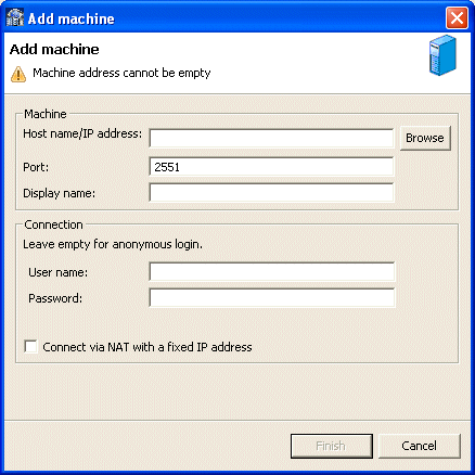
Right-click Machines in the Configuration Explorer and select Add Machine. The Add Machine screen is displayed.
-
Enter the name of the computer you want to connect to, or click Browse to select the computer from the list of computers that is displayed and which use the default port (2551).
-
Specify the user name and password of the user who was specified as the administrator when Oracle Connect was installed.
Note:
Selecting Anonymous connection enables anyone having access to the computer to be an administrator, if this was defined for the computer. -
Click Finish.
The computer is displayed in the Configuration Explorer.
Securing Access to Oracle Connect
Oracle Studio includes mechanisms to secure access to Oracle Connect both during modeling and at run time.
During modeling, the following security mechanisms can be applied:
At run time client access to Oracle Connect is provided by the user profile:
Setting Password Access to Oracle Studio
Initially, any operation performed using Oracle Studio does not require a password. You can set a password so that the first operation that involves accessing the server from Oracle Studio requires a password to be entered.
Perform the following steps to set password access to Oracle Studio:
-
From the Start menu, select, Programs, Oracle, and then select Studio. Oracle Studio opens.
-
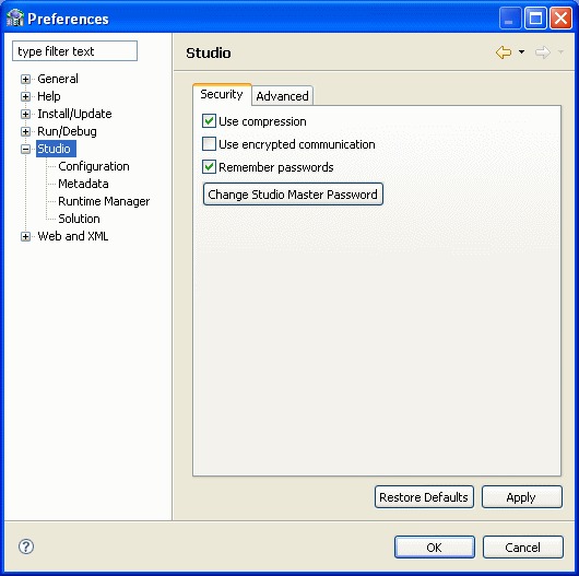
Select Window from the menu bar, and then select Preferences. The Preferences screen is displayed.
-
Click Studio in the left pane as shown in the following figure:
-
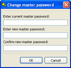
Click Change Studio Master Password. The Change Master Password screen is displayed, as shown in the following figure:
-
Leave the Enter current master password field blank and type a new master password in the Enter new master password field.
-
Enter the new passoword again in the Confirm new master password field.
-
Click OK.
Specifying Users with Administrative Rights
By default, only the user who was specified during the installation as an administrator has the authorization to modify settings on that computer from Oracle Studio. This user can then authorize other users to make changes or to view the definitions for a selected computer. Adding a computer to Oracle Studio is described in "Setting Up the IBM z/OS Platform in Oracle Studio".
Note:
The default during installation is to enable all users to be administrators.-
From the Start menu, select, Programs, Oracle, and then select Studio. Oracle Studio opens.
-
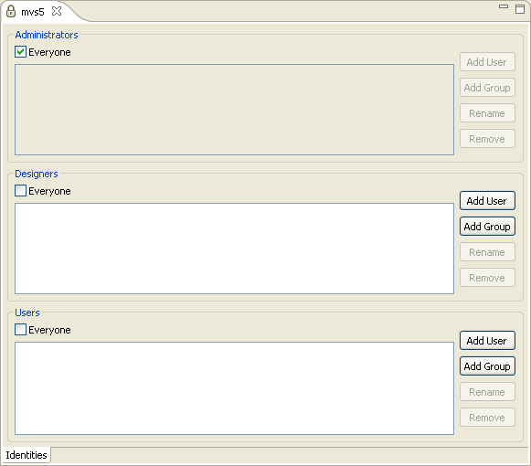
In the Design perspective Configuration view, Right-click the computer and select Administration Authorization.
The Administration Authorization screen is displayed as shown in the following figure:
The screen has the following sections:
Administrators: Administrators can view and modify all the definitions in Oracle Studio for the selected computer. On initial entry to Oracle Studio, every user is defined as a system administrator.
Designers: Designers can view all the definitions for the computer in Oracle Studio and can modify any of the definitions under the Bindings and Users nodes for the selected computer. For example, Oracle Studio database administrator can add new data sources and adapters and can change metadata definition for a table in a data source.
Users: Users can view all the definitions for the computer in Oracle Studio for the selected computer. Regular users cannot modify any of the definitions.
-
Add users or groups of users by clicking Add User or Add Group for the relevant sections.
The user or group that is added must be recognized as a valid user or group for the computer. Once a name has been added to a section, only the user or group that logs on with that user name has the relevant authorization.
Setting Up Run-Time User Access to the IBM z/OS Platform
During run time, client access to Oracle Connect is provided by the user profile. A user profile contains name and password pairs that are used to access a computer, data source or application at run time, when anonymous access is not allowed.
-
From the Start menu, select, Programs, Oracle, and then select Studio. Oracle Studio opens.
-
From the Design perspective, Configuration view, expand the Machines folder, then expand the machine where you want to set the user name and password.
-
Expand Users.
-
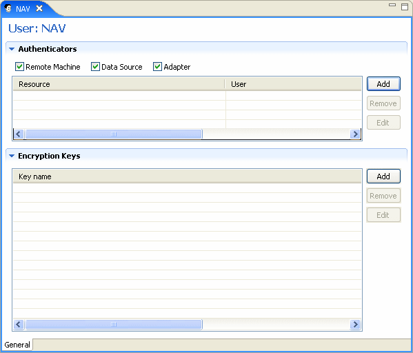
Right-click the NAV user profile and select Open. The NAV user profile editor is displayed:
-
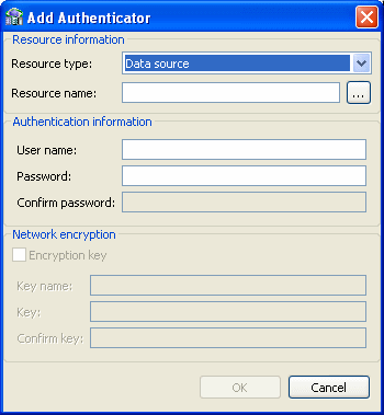
In the User editor, click Add. The Add Authenticator screen is displayed:
-
Select Remote Machine from the Resource Type list.
-
Enter the name of the z/OS computer defined in Oracle Studio.
-
Enter the name and password used to access the computer and confirm the password.
-
Click OK.
Setting up Metadata for the OracleAS IMS/DB Data Source
Setting up a change data capture with the OracleAS CDC Adapter for IMS/DB is done using Oracle Studio. The first step is to define an IMS/DB data source and import the metadata. The definitions are created on the z/OS computer.
Do the following to set up the Metadata:
Setting Up the IMS/DB Data Source
Oracle Connect requires you to specify the IMS/DB data source as the first step in setting up the adapter.
Do the following to set up the IMS/DB data source:
-
From the Start menu, select, Programs, Oracle, and then select Studio.
-
In the Design perspective, Configuration view, expand the machine folder.
-
Expand the computer defined in "Setting Up the IBM z/OS Platform in Oracle Studio".
-
Expand Bindings. The binding configurations available on this computer are listed.
-
Expand the NAV binding. The NAV binding configuration includes folders for data sources and adapters that are located on the computer.
-
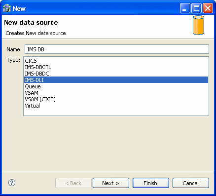
Right-click Data sources and select New data source, to open the New data source wizard.
-
In the New data source wizard, Create new data source page, enter a name for the IMS/DB data source. The name can contain letters and numbers and the underscore character only.
-
From the Type list, select IMS-DLI
-
Click Next. You do not need to enter a connect string for IMS-DLI.
-
Click Finish. The new data source is displayed in the Configuration view.
Configuring the Data Source Driver
After setting up the data source, you can set its driver properties according to specific requirements, as follows:
-
In the Configuration view, right-click the IMS/DB data source that you created and select Open.
-
Click the Configuration tab.
For IMS/DB direct, the following configuration property is available:
-
disableExplicitSelect=true | false: Set totrueto disable theExplicitSelect ADDattribute; every field is returned by aSELECTstatement.
-
-
Click Save to save the changes you made to the configuration properties.
Configuring the Data Source Driver Advanced Properties
You configure the advanced properties for a data source in the Advanced tab of the data source editor. The advanced settings are the same for every data source. Advanced settings let you do the following:
-
Define the transaction type
-
Edit the syntax name
-
Provide a table owner
-
Determine if a data source is updatable or readable
-
Provide repository information
-
Set the virtual view policy
Use the following procedure to configure the data source advanced features.
-
Open Oracle Studio.
-
In the Design Perspective Configuration View, expand the Machine folder and then expand the machine where you want to configure the data source.
-
Expand the Data sources folder, right click the data source you are configuring, then select Open.
-
Click the Advanced tab and make the changes. The following table describes the available fields:
Table 2-1 Data Source Advanced Configuration
| Field | Description |
|---|---|
|
Properties |
|
|
Transaction type |
The transaction level (0PC, 1PC or 2PC) that is applied to this data source, no matter what level the data source supports. The default is the data source's default level. |
|
Syntax name |
A section name in the
|
|
Default table owner |
The name of the table owner that is used if an owner is not indicated in the SQL |
|
Read/Write information |
Select one of the following:
|
|
Repository Directory |
|
|
Repository directory |
Enter the location for the data source repository. |
|
Repository name |
Enter the name of a repository for a data source. The name is defined as a data source in the binding configuration. It is defined as the type |
|
Virtual View Policy |
|
|
Generate sequential view |
Select this to map a non-relation file to a single table. This parameter is valid only if you are using virtual array views. You configure virtual array views in the Modeling section of thewhen Configuring a Binding Environment. |
|
Generate virtual views |
Select this to have an individual table created for every array in the non-relational file. This parameter is valid only if you are using virtual array views. You configure virtual array views in the Modeling section when Configuring a Binding Environment. |
|
Include row number column |
Select this to include a column that specifies the row number in the virtual or sequential view. This parameter is valid only if you are using virtual array views. You configure virtual array views in the Modeling section when Configuring a Binding Environment. |
|
All parent columns |
Select this for virtual views to include all the columns in the parent record. This parameter is valid only if you are using virtual array views. You configure virtual array views in the Modeling section when Configuring a Binding Environment. |
Importing Metadata for the IMS/DB Data Source
Oracle Connect requires metadata describing the IMS/DB data source records and the fields in these records. Use the Import Metadata procedure in Oracle Studio Design perspective to import metadata for the IMS/DB data source from DBD, COBOL copybooks and PSB files, which describe the data.
The following information is needed during the import procedure:
-
DBD files: These files are copied to the computer running Oracle Studio as part of the import procedure.
-
COBOL copybooks: These copybooks are copied to the computer running Oracle Studio as part of the import procedure.
-
PSB file: This file is copied to the computer running Oracle Studio as part of the import procedure.
The metadata import procedure has the following steps:
Selecting the Imput Files
-
From the Start menu, select, Programs, Oracle, and then select Studio.
-
In the Configuration view, expand the computer defined in "Setting Up the IBM z/OS Platform in Oracle Studio".
-
Expand Bindings. The binding configurations available on this computer are listed.
-
Expand NAV binding.
-
Expand Data sources.
-
Right-click the IMS/DB data source defined in Setting Up the IMS/DB Data Source.
-
Select Show Metadata View, to open the Metadata tab, with the IMS/DB data source displayed under the data sources list.
-
Right-click the IMS/DB data source and select New Import.
The New Import screen is displayed.
-
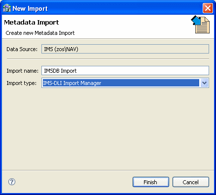
Enter a name for the import. The name can contain letters and numbers and the underscore character only.
-
From the Import Type list select IMS-DLI Import Manager. This should be the only choice in the list. The New Import wizard is shown in the following figure:
-
Click Finish. The Metadata Import wizard opens.
-
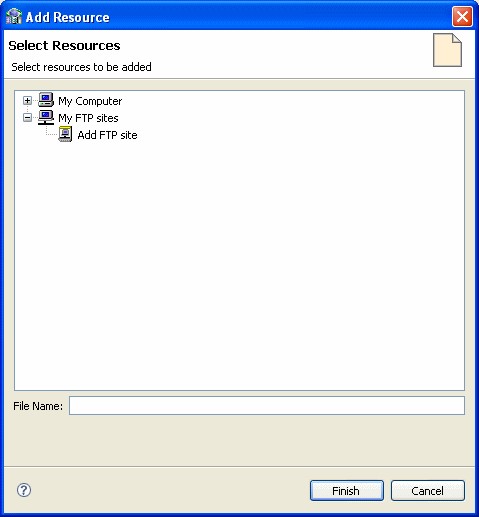
Click Add in the Import Wizard to add DBD files. The Add Resource screen is displayed, providing the option of selecting files from the local computer time stamp or copying the files from another computer.
-
Click Add.
The Select Resources screen is displayed, which provides the option to select files from the local computer or copy the files from another computer.
-
If the files are on another computer, right-click My FTP Sites and select Add. Optionally, double-click Add FTP site. The Add FTP Site screen is displayed.
-
Set the FTP data connection by entering the server name where the DBD files reside and, if not using anonymous access, enter a valid user name and password to access the computer.
-
To browse and transfer files required to generate the metadata, access the computer using the user name as the high-level qualifier.
After accessing the computer, you can change the high-level qualifier by right-clicking the computer and selecting Change Root Directory.
-
Select the files to import and click Finish to start the transfer.
-
Repeat the procedure for COBOL copybooks.
The format of the COBOL copybooks must be the same. For example, you cannot import a COBOL copybook that uses the first six columns with a COBOL copybook that ignores the first six columns. In this type of case, repeat the import process.
You can import the metadata from one COBOL copybook and later add to this metadata by repeating the import using different COBOL copybooks.
-
Click Add in the Import wizard to add a PSB file, if necessary.
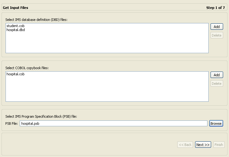
The selected files are displayed in the Get Input Files screen. The following figure shows the Get Imput Files screen.
-
Click Next to go to the Applying Filters step.
Applying Filters
This section describes the steps required to apply filters on the COBOL Copybook files used to generate the Metadata. It continues the Selecting the Imput Files step.
Perform the following steps to apply filters.
-
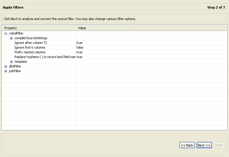
Apply filters to the copybooks, as needed.
The following is theApply Filters editor.
The following COBOL filters are available:
-
COMP_6 switch: The MicroFocus COMP-6 compiler directive. Specify either COMP-6'1' to treat COMP-6 as a COMP data type or COMP-6'2' to treat COMP-6 as a COMP-3 data type.
-
Compiler source: The compiler vendor.
-
Storage mode: The MicroFocus Integer Storage Mode. Specify either NOIBMCOMP for byte storage mode or IBMCOMP for word storage mode.
-
Ignore after column 72: Ignore columns 73 to 80 in the COBOL copybooks.
-
Ignore first 6 columns: Ignore the first six columns in the COBOL copybooks.
-
Prefix nested column: Prefix all nested columns with the previous level heading.
-
Replace hyphens (-) in record and field names with underscores (_): A hyphen, which is an invalid character in Oracle metadata, is replaced with an underscore.
-
Case sensitive: Specifies whether to consider case sensitivity or not.
-
Find: Searches for the specified value.
-
Replace with: Replaces the value specified for in the Find field with the value specified here.
The following DBD filters are available:
-
Ignore after column 72: Ignore columns 73 to 80 in the COBOL copybooks.
-
Ignore first 6 columns: Ignore the first six columns in the COBOL copybooks.
-
Ignore labels: Ignore labels in the DBD files.
The following PSB filters are available:
-
Ignore after column 72: Ignore columns 73 to 80 in the COBOL copybooks.
-
Ignore first 6 columns: Ignore the first six columns in the COBOL copybooks.
-
-
Click Next to go to the Selecting Tables step.
Selecting Tables
This section describes the steps required to select the tables from the COBOL Copybooks.
The following procedure continues the Applying Filters step. Perform these steps to select the tables.
-
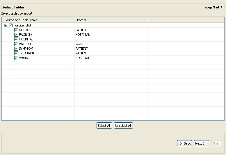
From the Select Tables screen, select the tables to access. To select all tables, click Select All. To clear all the selected tables, click Unselect All.
The Select Tables screen is shown in the following figure:
The import manager identifies the names of the segments in the DBD files that are imported as tables.
-
Click Next (the Import Manipulation screen opens) to continue to the Matching DBD to COBOL step.
Matching DBD to COBOL
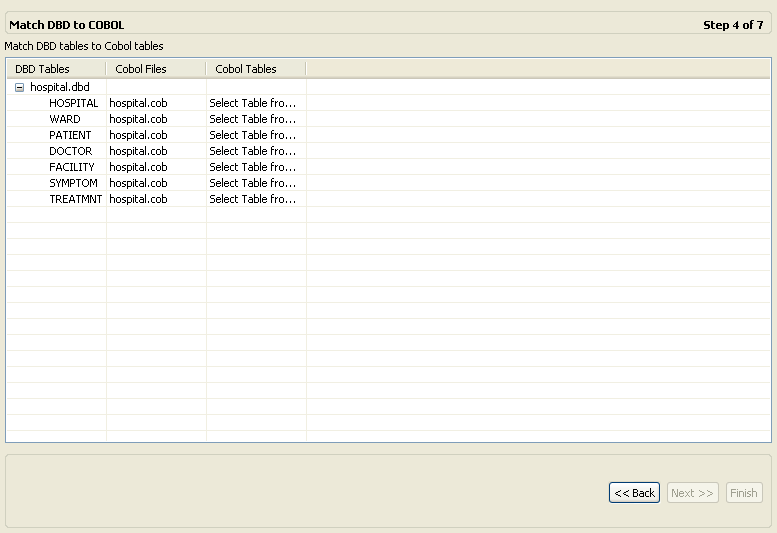
This step lets you match the DBD file to your COBOL copybook. It is a continuation of the Selecting Tables step. The following figure shows the DBD to COBOL step that is displayed in the Editor.
-
Match each table selected from the DBD file with the COBOL copybook that contains the relevant table structure. Select the files and tables from the dropdown lists for each DBD entry.
-
Click Next (the Import Manipulation screen opens) to continue to the Import Manipulation step.
Import Manipulation
This section describes the operations available for manipulating the imported records (tables). It continues the Matching DBD to COBOL step.
The import manager identifies the names of the records in the DDM Declaration files that are imported as tables. You can manipulate the general table data in the Import Manipulation Screen.
Perform the following steps to manipulate the table metadata.
-
From the Import Manipulation screen (see Import Manipulation Screen figure), right-click the table record marked with a validation error, and select the relevant operation. For the available operations, see the table, Table Manipulation Options.
-
Repeat step 1 for all table records marked with a validation error. You resolve the issues in the Import Manipulation Screen.
Once all the validation error issues have been resolved, the Import Manipulation screen is displayed with no error indicators.
-
Click Next to continue to the Metadata Model Selection.
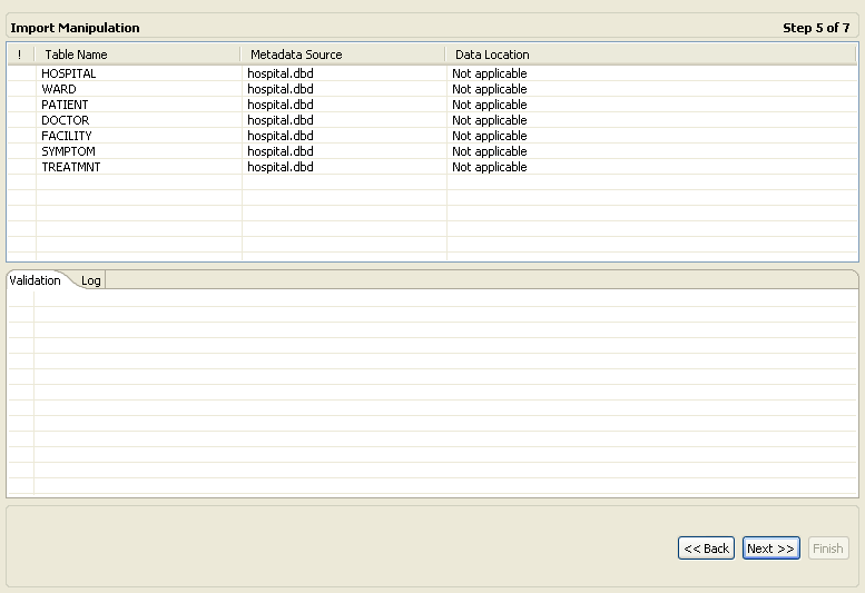
The Import Manipulation screen is shown in the following figure:
The upper area of the screen lists the DDM Declaration files and their validation status. The metadata source and location are also listed.
The Validation tab at the lower area of the screen displays information about what must be resolved to validate the tables and fields generated from the COBOL. The Log tab displays a log of what has been performed (such as renaming a table or specifying a data location).
The following operations are available in the Import Manipulation screen:
-
Resolving table names, where tables with the same name are generated from different files during the import.
-
Selecting the physical location for the data.
-
Selecting table attributes.
-
Manipulating the fields generated from the COBOL, as follows:
-
Merging sequential fields into one (for simple fields).
-
Resolving variants by either marking a selector field or specifying that only one case of the variant is relevant.
-
Adding, deleting, hiding, or renaming fields.
-
Changing a data type.
-
Setting the field size and scale.
-
Changing the order of the fields.
-
Setting a field as nullable.
-
Selecting a counter field for array for fields with dimensions (arrays). You can select the array counter field from a list of potential fields.
-
Setting column-wise normalization for fields with dimensions (arrays). You can create new fields instead of the array field where the number of generated fields aredetermined by the array dimension.
-
Creating arrays and setting the array dimension.
-
The following table lists and describes the available operations when you right-click a table entry:
Table 2-2 Table Manipulation Options
| Option | Description |
|---|---|
|
Fields Manipulation |
Customizes the field definitions, using the Field Manipulation screen. You can also access this screen by double-clicking the required table record. |
|
Rename |
Renames a table. This option is used especially when several tables with the same name are generated from the COBOL. |
|
Set data location |
Sets the physical location of the data file for the table. |
|
Set table attributes |
Sets the table attributes. |
|
XSL manipulation |
Specifies an XSL transformation or JDOM document that is used to transform the table definitions. |
|
Remove |
Removes the table record. |
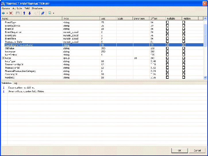
You can manipulate the data in the table fields in the Field Manipulation Screen. Double-click a line in the Import Manipulation Screen to open the Field Manipulation Screen.
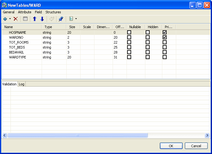
The Field Manipulation screen lets you make changes to fields in a selected table. You get to the Field Manipulation screen through the Import Manipulation Screen. The Field Manipulation screen is shown in the following figure.
You can perform all of the available tasks in this screen through the menu or toolbar. You can also right click anywhere in the screen and select any of the options available in the main menus from a shortcut menu. The following table describes the tasks that are done in this screen. If a toolbar button is available for a task, it is pictured in the table.
Table 2-3 Field Manipulation Screen Commands
| Command | Description |
|---|---|
|
General menu |
|
|
Undo |
Click to undo the last change made in the Field Manipulation screen. |
|
Select fixed offset |
The offset of a field is usually calculated dynamically by the server at run time according the offset and size of the proceeding column. Select this option to override this calculation and specify a fixed offset at design time. This can happen if there is a part of the buffer to skip. When you select a fixed offset you pin the offset for that column. The indicated value is used at run time for the column instead of a calculated value. Note that the offset of following columns that do not have a fixed offset are calculated from this fixed position. |
|
Test import tables |
Select this table to create an SQL statement to test the import table. You can base the statement on the Full table or Selected columns. When you select this option, the following screen opens with an SQL statement based on the table or column entered at the bottom of the screen. 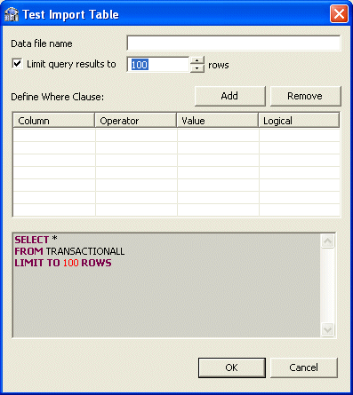
Enter the following in this screen:
The resulting SQL statement with any Where Clauses that you added are displayed at the bottom of the screen. Click OK to send the query and test the table. |
|
Attribute menu |
|
|
Change data type |
Select Change data type from the Attribute menu to activate the Type column, or click the Type column and select a new data type from the list. |
|
Create array |
This command lets you add an array dimension to the field. Select this command to open the Create Array screen. 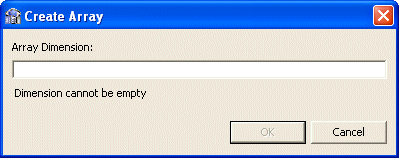
Enter a number in the Array Dimension field and click OK to create the array for the column. |
|
Hide/Reveal field |
Select a row from the Field manipulation screen and select Hide field to hide the selected field from that row. If the field is hidden, you can select Reveal field. |
|
Set dimension |
Select this to change or set a dimension for a field that has an array. Select Set dimension to open the Set Dimension screen. Edit the entry in the Array Dimension field and click OK to set the dimension for the selected array. |
|
Set field attribute |
Select a row to set or edit the attributes for the field in the row. Select Set field attribute to open the Field Attribute screen. 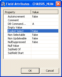
Click in the Value column for any of the properties listed and enter a new value or select a value from a list. |
|
Nullable/Not nullable |
Select Nullable to activate the Nullable column in the Field Manipulation screen. You can also click in the column. Select the check box to make the field Nullable. Clear the check box to make the field Not Nullable. |
|
Set scale |
Select this to activate the Scale column or click in the column and enter the number of places to display after the decimal point in a data type. |
|
Set size |
Select this to activate the Size column or click in the column and enter the number of total number of characters for a data type. |
|
Field menu |
|
|
Add |
Select this command or use the button to add a field to the table. If you select a row with a field (not a child of a field), you can add a child to that field. Select Add Field or Add Child to open the following screen: 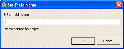
Enter the name of the field or child, and click OK to add the field or child to the table. |
|
Delete field |
Select a row and then select Delete Field or click the Delete Field button to delete the field in the selected row. |
|
Move up or down |
Select a row and use the arrows to move it up or down in the list. |
|
Rename field |
Select Rename field to make the Name field active. Change the name and then click outside of the field. |
|
Sturctures menu |
|
|
Columnwise Normalization |
Select Columnwise Normalization to create new fields instead of the array field where the number of generated fields are determined by the array dimension. |
|
Combining sequential fields |
Select Combining sequential fields to combine two or more sequential fields into one simple field. The following dialog box opens: 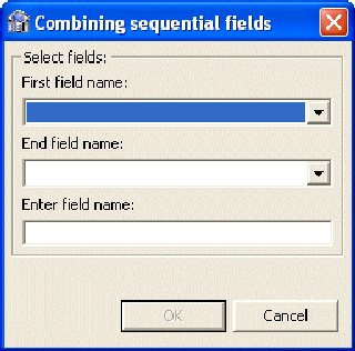
Enter the following information in the Combining sequential fields screen:
|
|
Flatten group |
Select Flatten Group to flatten a field that is an array. This field must be defined as 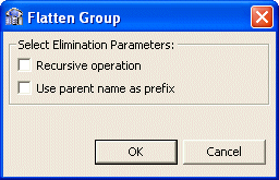
Do the following in this screen:
|
|
Mark selector |
Select Mark selector to select the selector field for a variant. This is available only for variant data types. Select the Selector field form the following screen. 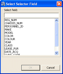 |
|
Replace variant |
Select Replace variant to replace a variant's selector field. |
|
Select counter field |
Select Counter Field opens a screen where you select a field that is the counter for an array dimension. 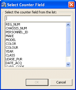 |
Metadata Model Selection
This section lets you generate virtual and sequential views for imported tables containing arrays. In addition, you can configure the properties of the generated views. It continues the Import Manipulation procedure. This lets you flatten tables that contain arrays.
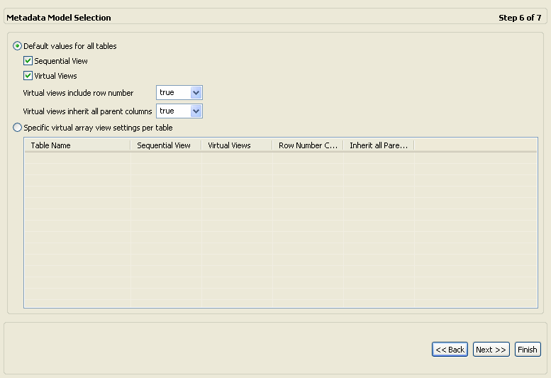
In the Metadata Model Selection step, you can select configure values that apply to all tables in the import or set specific settings for each table. The following describes how to configurations available in the The Metadata Model Selection editor.
-
Select one of the following:
-
Default values for all tables: Select this to configure the same values for all the tables in the import. Make the following selections when using this option:
-
Generate sequential view: Select this to map non-relational files to a single table.
-
Generate virtual views: Select this to have individual tables created for each array in the non-relational file.
-
Include row number column: Select one of the following:
true: Select true, to include a column that specifies the row number in the virtual or sequential view. This is true for this table only, even if the data source is not configured to include the row number column.
false: Select false, to not include a column that specifies the row number in the virtual or sequential view for this table even if the data source is configured to include the row number column.
default: Select default to use the default data source behavior for this parameter.
For information on how to configure these parameters for the data source, see Configuring the Data Source Driver Advanced Properties.
-
Inherit all parent columns: Select one of the following:
true: Select true, for virtual views to include all the columns in the parent record. This is true for this table only, even in the data source is not configured to include all of the parent record columns.
false: Select false, so virtual views do not include the columns in the parent record for this table even if the data source is configured to include all of the parent record columns.
default: Select default to use the default data source behavior for this parameter.
For information on how to configure these parameters for the data source, see Configuring the Data Source Driver Advanced Properties.
-
-
Specific virtual array view settings per table: Select this to set different values for each table in the import. This overrides the data source default for that table. Make the selections in the table under this selection.
-
When you are finished, click Next to go to the Import the Metadata step.
The Metadata Model Selection editor is shown in the following figure:
Import the Metadata
This section describes the steps required to import the metadata to the target computer. It continues the Metadata Model Selection step.
You can now import the metadata to the computer where the data source is located, or import it later (in case the target computer is not available).
Perform the following steps to transfer the metadata.
-
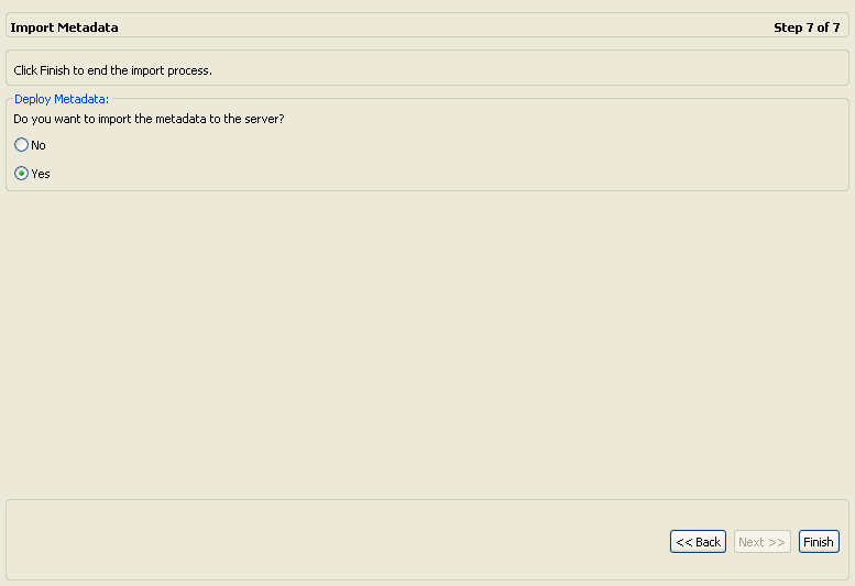
Select Yes to immediately transfer the metadata from the Windows computer to the z/OS platform, or No to transfer the metadata later.
The metadata is imported based on the options selected in the previous steps and it is stored on the IBM z/OS platform computer. An XML representation of the metadata is generated. This XML file can be viewed by expanding the Output node.
-
Click Finish.
After performing the import, you can view the metadata in the Metadata tab in Oracle Studio Design perspective. You can also make any fine adjustments to the metadata and maintain it, as necessary.
See Also:
Metadata for the IMS/DB Data Source for details about the data source metadata.The Import Metadata screen is shown in the following figure:
After performing the import, you can view the metadata in the Metadata tab in Oracle Studio. You can also make any fine adjustments to the metadata and maintain it, as necessary.
Verifying the Metadata Definition
After you finish Importing Metadata for the IMS/DB Data Source, you must verify that the metadata is correct. Do the following to verify that the metadata was imported correctly.
-
From the Start menu, select Programs, Oracle and then select Studio.
-
In the Design perspective, Configuration view expand the Machines folder.
-
Expand the machine defined in Setting Up the IBM z/OS Platform in Oracle Studio.
-
Expand the Bindings folder. The binding configurations available on this computer are listed.
-
Expand the NAV binding. The NAV binding configuration includes branches for data sources and adapters that are located on the computer.
-
Expand the Data Sources folder.
-
Right-click the data source that you set up when Setting Up the IMS/DB Data Source, and select Show Metadata View. The Metadata view opens with the data source you selected expanded.
-
Expand the Tables folder.
-
Right-click the table or tables where you carried out the metadata import and select Test. The Test wizard opens.
-
Click Next to view the metadata. The tables are displayed from the metadata. Check to see that the correct information is displayed.
Setting Up a Change Data Capture with the OracleAS CDC Adapter for IMS/DB
You must set up the Oracle Connect IMS/DB CDC adapter on the z/OS platform to handle capture changes to the IMS/DB data. To work with the IMS/DB CDC adapter, you must configure the DFSFLGX0 exit and set up the security parameters on the z/OS computer and then configure the change data capture using the Oracle Studio CDC Solution perspective. Oracle Studio must be installed on a Windows or UNIX computer.
Perform the following steps to setup the change data capture and configure the CDC adapter:
Configuring the DFSFLGX0 Exit
To use the DFSFLGX0 exit, perform the following procedures:
In addition, the CDC$PARM Properties are listed in this section.
MVS Logstream Creation
A sample job for the creation of the DASD MVS logstream called Oracle.IMS.DCAPDATA is supplied in the <HLQ>.USERLIB(LOGCRIMS) member. For additional information, see the MVS Setting Up a Sysplex IBM manual.
The ATYLOGR program that is provided is used to manage MVS logstreams. It provides the following options:
-
Delete all events
-
Delete events to a specific time stamp
-
Print events between two time stamps
-
Print all events from the oldest to a selected time stamp
-
Print all events from the newest to a selected time stamp
-
Print all events
Creating and Configuring the CDC$PARM Data Set
The CDC$PARM is the DD card name used for configuring the DFSFLGX0 exit. It can be any QSAM data set or member with the LRECL=80 definition. For example, you can build it as a member of the <HLQ>.USERLIB library.
The data set contains parameters, one parameter on a line, according to the follow syntax:
<parameter name>=<parameter value>
The parameters and their valid values are described in CDC$PARM Properties.
Update the IMS Environment
You must do the following to update the IMS Environment:
-
Copy the supplied
DFSFLGX0exit module from the supplied<HLQ>. LOADCDIMlibrary to theIMS RESlibrary. -
If necessary, add the
CDC$PARMDD card to the IMS Control Region and batch jobs. -
Restart the IMS Control Region.
Adjust the DBD for the Relevant Databases
You must do the following to adjust the DBD for the relevant databases:
-
Adjust the DBD for each IMS/DB database that is included in your CDC solution, defining the usage of
DFSFLGX0 exit, by adding the following parameter to the DBD macro:EXIT= (*, KEY, NOPATH, DATA, LOG, (CASCADE, KEY, NODATA, NOPATH))
-
Recompile DBD and the corresponding PSB and ACB objects, then restart the IMS Control Region.
CDC$PARM Properties
CDC$PARM is the name of DD card that defines a QSAM data set or PDS member that contains the parameters for a DFSFLGX0 user exit. For an explanation on how to create this and its syntax, see Creating and Configuring the CDC$PARM Data Set. The following list describes the CDC$PARM properties:
-
BUFFER_NUM: The logstream buffer number. The valid values areDefault-30. -
BUFFER_SIZE: The logstream buffer size. The valid values areDefault-22550bytes. -
DEBUG: If this isONthe debug information is printed using WTO. The default value isOFF. -
LOGSTREAM: The logstream name. The default value isOracle.IMS.DCAPDATA.
Setting up Security for the OracleAS CDC Adapter
The IMS/DB CDC adapter connects to the MVS logstream with an authorization level of READ. The DFSFLGX0 user exit connects to the logstream with an authorization level of WRITE. To determine the proper security authorizations, see the MVS Auth Assm Services Reference ENF-IXG IBM manual.
Notes:
To access a logstream in an application with a READ authorization level, set the READ access to RESOURCE(<logstream name>) in SAF class CLASS(LOGSTRM).
To update a logstream in a program with a WRITE authorization level, set the ALTER access to RESOURCE(<logstream name>) in SAF class CLASS(LOGSTRM).
Setting up a Change Data Capture in Oracle Studio
You set up the change data capture in Oracle Studio. Oracle Studio can be installed on Windows XP or Vista operating systems, or on UNIX.
A change data capture is defined in the CDC Solution perspective, which contains a series of links to guide you through the CDC set up process. The CDC solution perspective guides display the following symbols in front of a link to show you what tasks should be done, and what tasks were completed.
-
Triangle: This indicates that there are subtasks associated with this link. When you click the link, the list expands to display the subtasks.
-
Asterisk (*): This indicates that you should click that link and perform the tasks and any subtasks presented. If several links have an asterisk, you can perform the marked tasks in any order.
-
Check mark (✓): This indicates that the tasks for this link and any sublink are complete. You can double click the link to edit the configuration at any time.
-
Exclamation mark (!): This indicates a potential validation error.
Perform the following to set up a change data capture:
Create a CDC Project
Do the following to create a CDC Project
-
From the Start menu, select, Programs, Oracle, and then select Studio.
-
Open the CDC Solution perspective, click the Perspective button on the perspective toolbar and select CDC Solution from the list.
The CDC Solution perspective opens with the Getting Started guide in the left pane of the workbench.
-
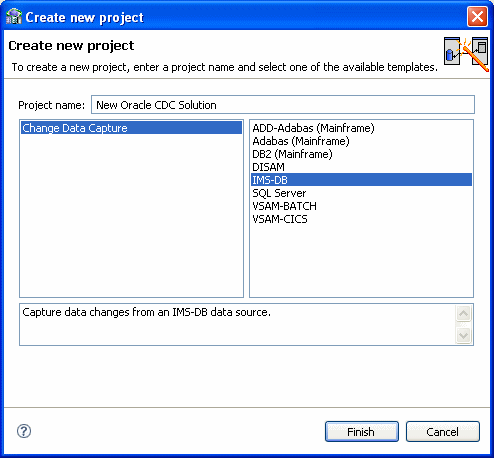
Click Create new project.
The Create new project screen opens.
-
In the Project name field, enter a name for your project.
The types of projects available are listed in the left pane.
-
Select Change Data Capture.
From the right pane, select IMS-DB.
-
Click Finish. The Project Overview guide is displayed in the left pane.
-
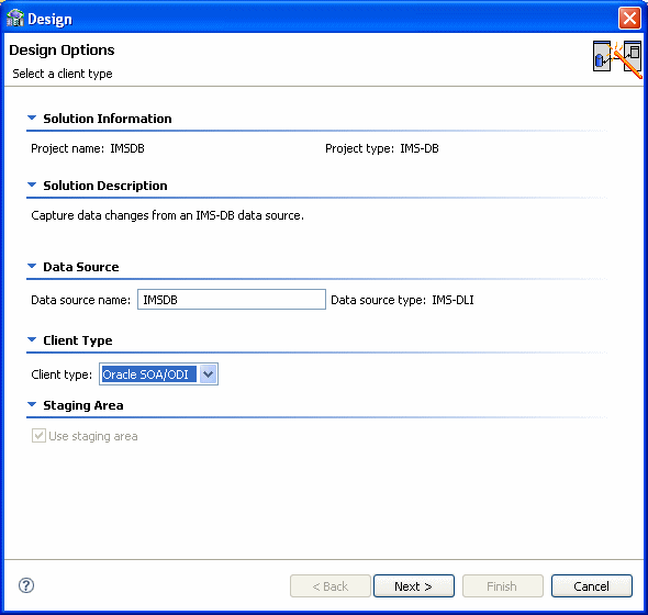
Click Design. The Design wizard opens. Use this wizard to enter the basic settings for your project.
Note:
The wizard screens are divided into sections. Some sections provide information only and other sections let you to enter information about the project. If you do not see any information or fields for entering information, click the triangle next to the section name to expand the section. -
In the Client Type you can select Oracle SOA/ODI only. The Use staging area is selected and cannot be changed, you must use a staging area with the OracleAS CDC Adapter for IMS/DB.
-
Click Next.
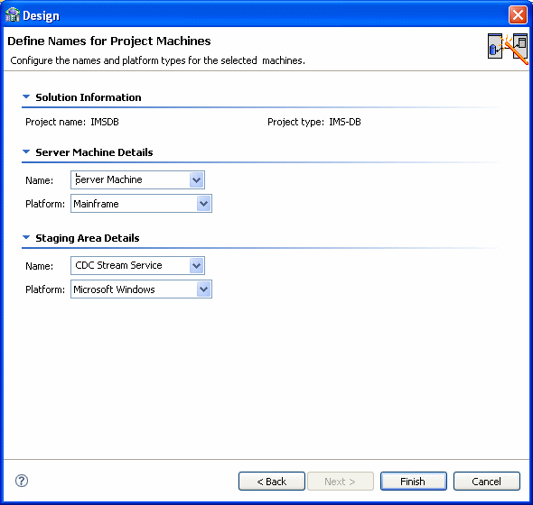
The Design Wizard's second screen is displayed. In this step you configure the computers used in your solution. Enter the following information:
-
Server Machine Details: Information about the computer where Oracle Connect is installed. The selection here is always Server Machine and Mainframe.
-
Staging Area Details: Information about the computer platform where the staging area is located.
For the server machine Name, select one of the following:
-
CDC Stream Service: Select this if the Staging Area is on a staging area computer. This is the default selection.
-
Server Machine: Select this if the staging area is on the same computer where Oracle Connect is installed.
-
Client Machine: Select this if the Staging area is on the local compuer.
In the Platform list, select the operating system for the staging area. This can be Windows, Linux or UNIX. The available options are:
-
Microsoft Windows
-
HP-UX
-
IBM AIX
-
Sun Solaris
-
Linux (Red Hat)
-
Suse (Linux)
-
-
-
Click Finish. The wizard closes.
Set up the CDC Server
Click Implement in the Getting Started guide to open the Implementation guide.
In the Implementation guide, do the following to set up the CDC server:
You do the following to define the IP Address/host name and Port for the CDC server computer.
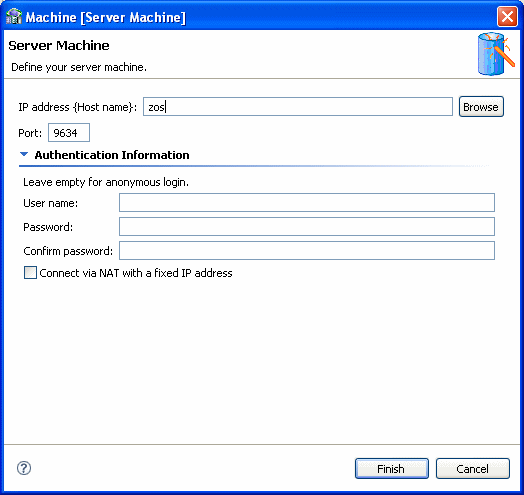
-
Click Machine.
The machine definition screen is displayed:
-
In the IP address/host name field, do one of the following:
-
Enter the server machine's numeric IP address.
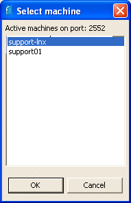
-
Click the Browse button and select the host machine from the ones presented, then click Finish.
Note:
The machine you enter must be compatible with the platform designated in the screen.
-
-
Enter the port number.
The default port number is 2551.
-
To connect with user authentication, enter a user name and password, with confirmation, in the Authentication Information area.
-
Select the Connect via NAT with a fixed IP address check box if you are using Network Access Translation and want to always used a fixed IP address for this machine.
-
Click OK.
Continue setting up the CDC Server on the z/OS computer.
In this step, copy the metadata that you imported when Importing Metadata for the IMS/DB Data Source. Do the following to copy the metadata.
-
Click Metadata.
The Create metadata definitions view is displayed.
Note:
The Select Metadata Source link has an asterisk (*) next to it to indicate that you must perform this operation first. -
Click the Select Metadata Source link.
-
Select Copy from existing metadata.
-
Click Finish. The screen closes.
-
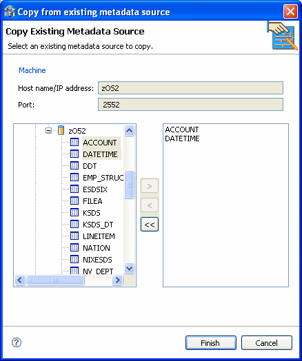
Click Copy from existing metadata source.
The Copy Existing Metadata Source screen is displayed showing your local computer and with metadata compatible with the data source selected.
-
From the sources in the left pane, expand the list until you see the tables from the data source you configured when Importing Metadata for the IMS/DB Data Source.
-
Using the arrow buttons, select the required tables and move them into the right pane.
-
Once you have selected all the desired tables, click Finish.
-
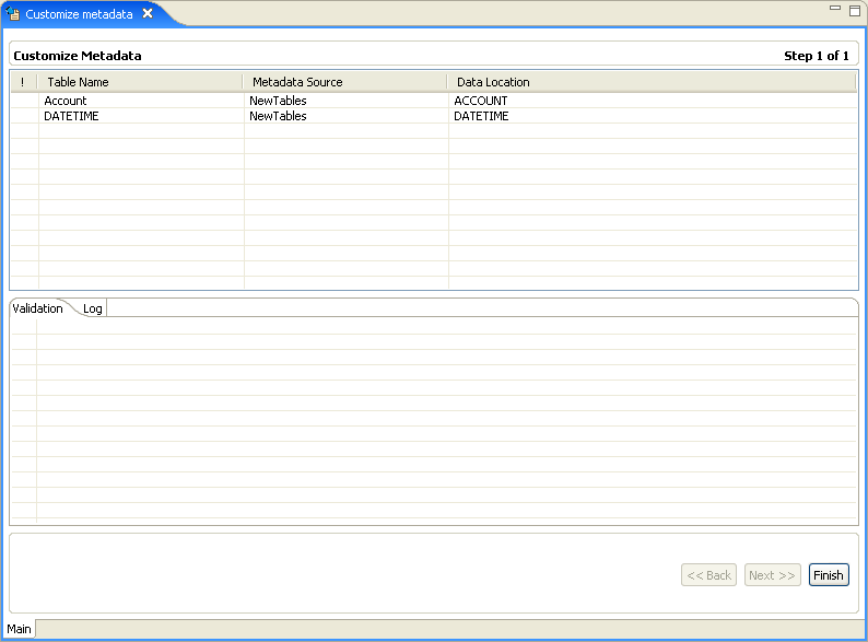
Click Customize Metadata.
The customize metadata screen is displayed.
Note:
If you do not want to make any custimizations to the metadata, click Finish to close this screen. A check mark (✓) appears next to Customize Metadata indicating that this step is complete.Continue with another step in the design wizard.
-
To change a table name, right-click in the any field under Customize Metadata, and select Add.
-
Enter the table name in the field presented, and click OK.
Note:
You may have validation errors in the tables created, which you can correct by the end of the procedure. -
To make changes to any field in a table, right-click the table created and select Fields Manipulation.
The Field Manipulation screen is displayed.
-
Right-click in the upper pane and select Field|Add|Field.
-
Enter the name of the field in the screen provided, and click OK.
-
Default values are entered for the table. To manipulate table information or the fields in the table, right-click the table and choose the option you want. The following options are available:
-
Add table: Add a table.
-
Field manipulation: Access the field manipulation window to customize the field definitions.
-
Rename: Rename a table name. This option is used especially when several tables are generated from the COBOL with the same name.
-
Set data location: Set the physical location of the data file for the table.
-
Set table attributes: Set table attributes.
-
XSL manipulation: You specify an XSL transformation or JDOM document that is used to transform the table definition.
The Validation tab at the bottom of the window that displays information about what you must do to validate the tables and fields generated from the COBOL. The Log tab displays a log of what has been performed (such as renaming a table or specifying a data location).
-
-
Correct any remaining validation errors.
-
Click Finish to generate the metadata.
Continue setting up the CDC Server on the z/OS computer.
In this step you define the starting point or event for the change capture and then indicate the name of the change logger. Do the following to set up the CDC service.
-
In the Solution perspective, click Implement.
-
In the Server Configuration section, click CDC Service. The CDC Service wizard is displayed.
-
In the first screen select one of the following to determine the Change Capture starting point:
-
All changes recorded to the journal
-
On first access to the CDC (immediately when a staging area is used, otherwise, when a client first requests changes
-
Changes recorded in the journal after a specific date and time.
When you select this option, click Set time, and select the time and date from the dialog box that is displayed.
-
-
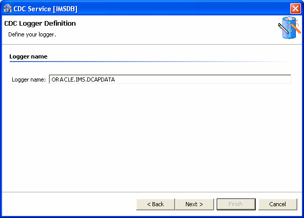
Click Next to define the logger. The following is displayed.
-
In the Logger Name field, enter the name for the logger, as entered in the IMS system fix 80 file. This is configured when Configuring the DFSFLGX0 Exit. the default name for the logger is
ORACLE.IMS.DCAPDATA. If you changed the name when configuring IMS, then enter the new name in this field. -
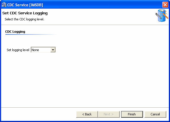
Click Next to go to the next step where you set the CDC Service Logging. Select the log level to use from the Logging level list.
Select one of the following from the list:
-
None
-
API
-
Debug
-
Info
-
Internal Calls
-
-
Click Finish.
Continue setting up the CDC Server on the z/OS computer.
Set up the Staging Area Server
Click Implement in the Getting Started guide to open the Implementation guide.
In the Implementation guide, do the following under the Stream Service Configuration section, to set up the staging area server:
Set Up the Staging Area Machine
To set up the machine for the staging area, do the following.
-
Under the Stream Service Configuration section, click Machine.
-
Use the same configurations used to Set up the Machine for the CDC server.
Continue setting up the staging area Server.
In this step you set up the stream service. The Stream Service configures the following:
-
Staging area
-
Filtering of changed columns
-
Auditing
Note:
Null filtering is currently unsupported. Filtering empty values is supported. Space values are truncated and are handled as empty values.-
Click Stream Service. The Stream Service wizard opens.
Note:
This screen appears only if you selected the inclusion of a staging area in your solution. -
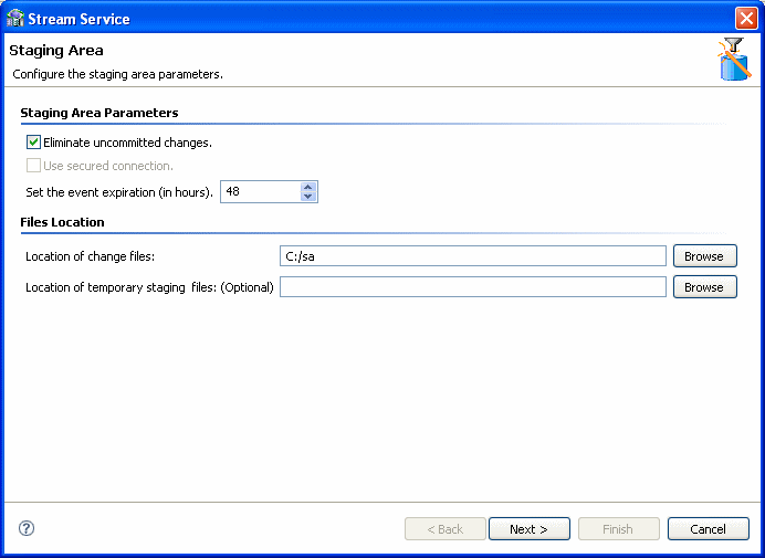
You can configure the following parameters in this screen:
-
Select Eliminate uncommitted changes to eliminate uncommitted changes from your CDC project.
-
Select the Use secured connection check box to configure the staging area to have a secured connection to the server. This is available only if you logged into the server using user name and password authentication.
-
Set the event expiration time in hours.
-
Under File Locations, click the Browse buttons to select the location of the changed files, and temporary staging files, if necessary.
-
-
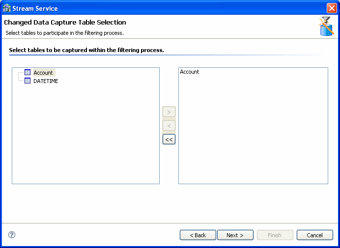
Click Next to select the tables to include in the filtering process.
-
Click the required tables in the left pane and move them to the right pane using the arrow keys.
Note: You can remove the tables and add new ones to be captured after you add the tables to the right pane. For more information, see Adding and Removing Tables.
-
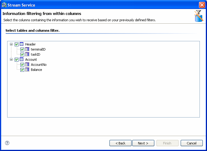
Click Next. From the tables selected above, select the columns that receive changes. Select the check box next to the table to use all columns in the table.
Note:
Table headers appear grouped in a separate table at the beginning of the list. You can also request the receipt of changes in the headers' columns.Any data changes in the columns selected are recorded.
-
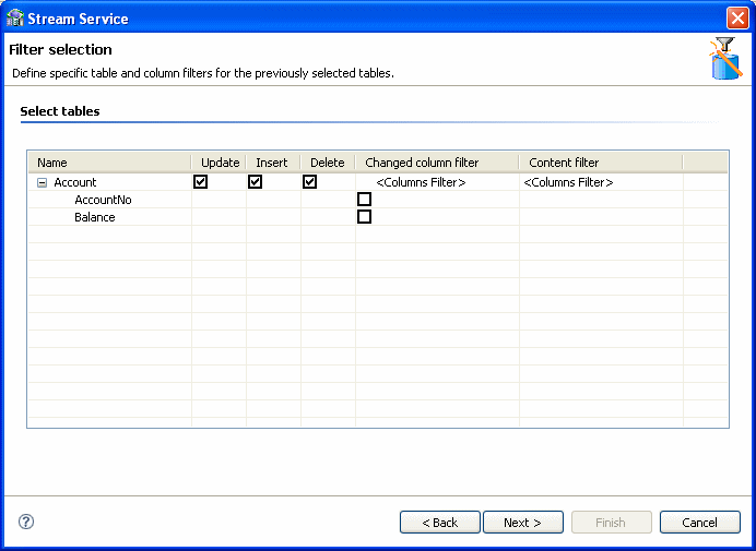
Click Next. The Filter selection screen is displayed. the types of changes you want to receive in the tables and which columns to display.
-
You can do the following in this screen:
Select the actions from which you want to receive change information:
-
-
Update
-
Insert
-
Delete
Note:
These items are all selected by default. -
-
Under the Changed Columns Filter column, select the columns for which you want to receive notification of changes.
Notes:
-
If you do not select a column, you receive notification of all changes.
-
If you select only one, you receive change information only if the field selected undergoes a change.
-
If you select several, but not all, then you receive change information only if any or all of the selected fields undergo a change
-
-
-
In the Content Filter column of the Filter screen, double-click a table column and then click the Browse button to filter content from the selected column.
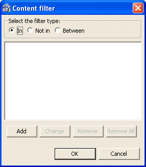
The Content Filter screen is displayed.
-
Select a filter type:
-
Select In for events to be returned where the relevant column value equals the values you specify (if a column is NULL, it is not captured).
-
Select Not In for events to be returned where the column value is not in the values you specify (if the column is NULL, it is captured).
-
Select Between for when the column value is between the two values you specify (if a column is NULL, it is not captured).
-
-
Click Add in the lower-left corner of the Content Filter screen.
Note:
If you select several conditions, you receive the change information if one condition is true. -
Depending on your selection, do one of the following:
-
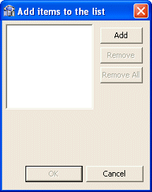
Click Add in the Add items to the list screen. Enter a value for events to be returned where the column value appears (or does not appear) in that value. To filter empty values ('') for the Not In filter type, leave this field blank in the dialog box that is displayed.
-
Repeat steps 12 as many times as necessary, and then proceed to step 16.
-
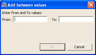
Click Add in the Add items to list screen.
The Add between values screen is displayed.
-
Enter values for events to be returned where the column value is between the two values you specify.
-
In the Content Filter screen, click Next.
-
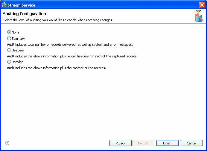
Select the required auditing level when receiving changes. Your options are:
-
None: For no changes.
-
Summary: For an audit that includes the total number of recorded delivered, system messages, and error messages.
-
Headers: For an audit that includes the total number of records delivered, system and error messages, and the record headers for each captured record.
-
Detailed: For an audit that includes the total number of records delivered, system and error messages, the record headers for each captured record, and the content of the records.
-
-
Click Finish.
Continue setting up the staging area Server.
Configure the Access Service Manager
In this step you set up a daemon workspace for the CDC adapter. Do the following to configure the access service manager.
-
Click Access Service Manager.
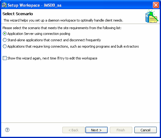
The Setup Workspace wizard opens.
-
Select the scenario that best meets your site requirements:
-
Application Server using connection pooling
-
Stand-alone applications that connect and disconnect frequently
-
Applications that require long connections, such as reporting programs and bulk extractors
-
-
Click Next.
The Application Server with connection pooling scenario screen is used to create a workspace server pool. The parameters available depend on the selection you made in the first screen. The following are the available parameters:
-
If you selected Application Server using connection pooling:
-
What is the average number of expected concurrent connections? Enter the number of expected connections, which cannot be greater than the number of acutal available connections.
-
What is the maximum number of connections you want to open? Enter the number of connections you want opened.
-
-
If you selected Stand-alone applications that connect and disconnect frequently, in addition to the choices listed in the item above, you can also set the following:
-
What is the minimum number of server instances you want available at any time? Enter the number of instances, which cannot be greater than the number of actual available instances.
-
What is themaximum number of server instances you want available at any time? Enter the number of instances you want to be available.
-
-
If you selected Stand-alone applications that connect and disconnect frequently:
-
How many connections do you want to run concurrently? Enter the number of concurrent connections to run.
-
-
-
Click Next. In the next screen you set time out parameters. These parameters should be changed if the system is slow or overloaded. The parameters are:
-
How long do you want to wait for a new connection to be established? Enter the amount of time you want to wait for a new connection to be established (in seconds).
-
How long do you want to wait for a response that is usually quick? Change this parameter if you have a fast connection. Enter the amount of time to wait for a response (in seconds).
-
-
Click Next. In the next screen you set security parameters. You should consult with the site security manager before changing these parameters.
Edit the following parameters in this screen:
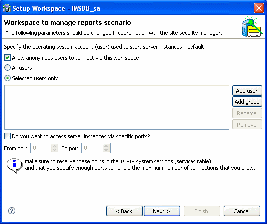
-
Enter the operating system account (user name) used to start server instances.
-
Select Allow anonymous users to connect via this workspace, to allow this option.
-
Enter the permissions for the workspace. You can allow All users to access the workspace, or select Selected users only to allow only the users/groups to have exclusive access.
-
Select Do you want to access server instances via specific ports, to allow this option. If this option is cleared, the defaults are used.
If you select this option, indicate the From port and To port and ensure that you reserve these ports in the TCP/IP system settings.
-
-
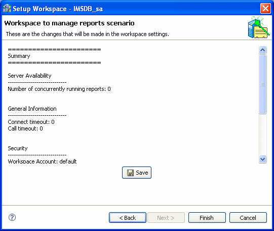
Click Next.
The summary screen opens.
-
Click Save and then click Finish.
When you complete all the Implementation operations, a check mark (✓) is displayed next to every link. Click Done to return so you can begin Deploying a Change Data Capture.
Continue setting up the staging area Server.
Deploying a Change Data Capture
After you complete the design and implementation guides, the following procedures are available.
-
Deployment Procedure: This section is used to deploy the project.
-
Control: This section is used to activate or deactivate workspaces after the project is deployed and you are ready to consume changes. In this section, you can deactivate the workspace anytime you want to suspend consumption of changes from the staging area.
Do the following to deploy the CDC solution:
-
Click Deploy. The Deployment Procedure and Control sections are displayed in the Deployment view.
-
Click Deploy in the Deployment Procedure section.
Oracle Studio processes the naming information. This may take a few minutes. If there are naming collisions, a message is displayed asking if you want Oracle Studio to resolve them.
-
Click Yes to resolve any naming collisions.
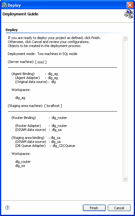
The Deployment Guide screen is displayed.
-
If you are ready to deploy, click Finish.
Otherwise, click Cancel and you can return to Create a CDC Project, Set up the CDC Server, or Set up the Staging Area Server to make any changes.
If this project was deployed previously, you are notified that re-deployment overrides the previous instance.
Notes:
-
When you redeploy a project where the metadata is changed, the Staging Area (SA) tables should be deleted so that no incorrect information is reported.
-
When you redeploy a solution, a new binding is created for the solution. The new binding is created with the default parameters only. Any temporary features that were added are lost.
-
-
Where applicable, click OK to redeploy.
-
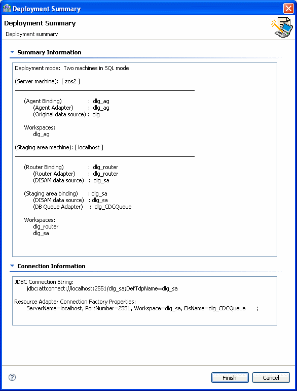
Click the Deployment Summary link.
The Deployment Summary is displayed. It includes the ODBC connection string, JDBC connection string, and specific logger scripts to enable CDC capturing.
-
Cut and paste any information required from the Deployment Summary screen to your environment as necessary.
-
If there is nothing wrong with your deployment results, click Finish.
If you found problems, click Cancel and to return Create a CDC Project, Set up the CDC Server, or Set up the Staging Area Server to modify the solution.
Note:
If you are redeploying a solution you must follow these directions to ensure that thecontext and agent_context fields of the SERVICE_CONTEXT table must be saved. Follow these directions to save the fields:
-
In the staging area data source run: select context,
agent_context from SERVICE_CONTEXT; and save the returned values. -
Delete the
SERVICE_CONTEXTtable physical files. -
Redeploy the solution.
-
Activate the router to create the
SERVICE_CONTEXTtable. -
Disable the router.
-
In the staging area data source run:
insert into SERVICE_CONTEXT (context, agent_context) values('XXX', 'YYY'). This inserts the saved values to the SERVICE_CONTEXT table. -
Activate the solution.
Activating and Deactivating Solution Workspaces
In the Project guide for your OracleAS CDC Adapter solution, click Deploy, then do one of the following to activate or deactivate the workspaces for a solution
-
To activate workspaces, under the Control section iclick the Activate Workspaces link.
-
To deactivate workspaces, click the Deactivate Workspaces link.
During the activation/deactivation process, you may receive messages indicating that the daemon settings on one or more of the machines involved in your solution have changed. Click Yes to proceed.
