| Oracle® Communications Service Broker Developer's Guide for GSM Release 5.0 Part Number E20060-01 |
|
|
View PDF |
| Oracle® Communications Service Broker Developer's Guide for GSM Release 5.0 Part Number E20060-01 |
|
|
View PDF |
The following sections describe how to develop a SIP call control application:
Note:
The following sections contain tables that specify the IN protocols for which the functionality described in that section is relevant.When Service Broker invokes a call control application, the application can perform one of the following actions:
Rejecting the call
Allowing the call to continue leaving the call information unmodified
Allowing the call to continue with the call information modified. The application performs this action by providing Service Broker with the call routing information. When Service Broker receives the call routing information, Service Broker propagates this information towards the MSC through the IN interface.
If the application decides to allow the call to continue, the application can do this in one of the following forms:
Routing the call while retaining call control for the entire call duration. An application that retains call control for the entire call duration is known as a full call control application.
Routing the call without retaining call control for the entire call duration. An application that routes the call to destination without retaining call control for the entire call duration is known as initial call control application.
Acting as a standard SIP entity, Service Broker invokes a SIP application by sending a SIP INVITE message. The Service Broker sets the SIP INVITE content based on the information received in the CAP InitialDP operation.
Table 2-2 shows the content of the SIP INVITE message as set by Service Broker. The SIP Header column describes the SIP INVITE headers. The Source column includes the source of the information used by Service Broker to set the SIP INVITE message.
Table 2-2 Service Broker Mapping of CAP 4 InitialDP Operation to SIP INVITE Message
| SIP Header | Source |
|---|---|
|
Request-URI :: User part (see the note for Request-URI below the table) |
InitialDP :: CalledPartyNumber OR InitialDP :: CalledPartyBCDNumber CalledPartyBCDNumber is used only when CalledPartyNumber is not included in InitialDP. |
|
Request-URI :: Domain part |
Service Broker configuration |
|
To :: User part |
Equals to the value set in RequestURI :: User part |
|
To :: Domain part |
Service Broker configuration |
|
From :: User part |
InitialDP :: AdditionalCallingPartyNumber If AdditionalCallingPartyNumber is not included in InitialDP, the From header is set from InitialDP :: CallingPartyNumber. If InitialDP :: CallingPartyNumber :: Address presentation restricted indicator is set to "presentation restricted": The From header is set as follows: From: "Anonymous" sip:anonymous@anonymous.invalid The Privacy header is set as follows: Privacy: id |
|
From :: Domain part |
Service Broker configuration |
|
P-Asserted-Identity :: User part (see the note for P-Asserted-Identity below the table) |
InitialDP :: CallingPartyNumber |
|
P-Asserted-Identity :: Domain part |
Service Broker configuration |
Notes to Table 2-2:
Request-URI
Service Broker sets the Request-URI with a noa token. For more information on the noa token, see "Exposing Nature of Address".
P-Asserted-Identity
The Service Broker sets the P-Asserted-Identity with a noa token. For more information on the noa token, see "Exposing Nature of Address".
Service Broker exposes CAP nature of address information towards the SIP application using a vendor specific token, named noa. The noa token carries the nature of address of various call parties as follows:
Nature of address of the called party number provided by noa token in the Request-URI header of the SIP INVITE, which is sent to the application
Nature of address of the calling party number provided by noa token in the P-Asserted-Identity header of the SIP INVITE, which is sent to the application
Table 2-4 describes how Service Broker sets the noa token for various nature of address values.
| Call party nature of address | NOA token content |
|---|---|
|
subscriber number (national use) |
subscriber |
|
unknown (national use) |
unknown |
|
national (significant) number (national use) |
national |
|
International |
noa token is not used |
As shown in Table 2-4, Service Broker does not set the noa token for nature of address of type “International”. When the nature of address of one of the call parties is set to “International”, the user part in the corresponding SIP header is prefixed with “+”. For example:
For the calling party nature of address of type “International”, Service Broker sets the P-Asserted-Identity in the SIP INVITE, which is sent to the application, as follows:
P-Asserted-Identity:
<sip:+97297888019@domain:5060>
For the calling party nature of address of type “national (significant) number”, Service Broker sets the P-Asserted-Identity in the SIP INVITE, which is sent to the application, as follows:
P-Asserted-Identity:
<sip:97888019@domain:5060;noa=national>
Table 2-5 Developing an Initial Call Control Application: Applicable CAP Phases
| CAP 1 | CAP 2 | CAP 3 | CAP 4 |
|---|---|---|---|
|
YES |
YES |
YES |
YES |
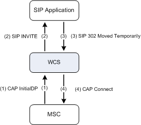
To provide an initial call control, the application responds to the SIP INVITE message with a SIP 302 Moved Temporarily message.
An initial call control application can perform one of the following actions:
Updating the called party number (that is to replace the number dialed by the calling party with a new number)
Leaving the called party number unmodified
The following sections describe how to implement these two options.
Note:
An initial call control application may also reject a call. This functionality is described in "Rejecting a Call".Table 2-6 Updating the Called Party Number: Applicable CAP Phases
| CAP 1 | CAP 2 | CAP 3 | CAP 4 |
|---|---|---|---|
|
YES |
YES |
YES |
YES |
To update the called party number (that is to replace the number dialled by the calling party with a new number), the application sets the SIP 302 Moved Temporarily to the new destination address.
The new destination address is set in the user part of the Contact header. This makes Service Broker to respond to the CAP InitialDP with a CAP Connect operation.
Note:
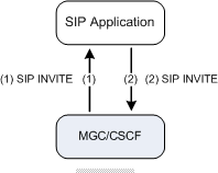
The application should set the user part with digits only.Figure 2-1 shows the high level architecture for an initial call control application that updates the called party number.
Figure 2-1 Architecture for Updating the Called Party Number by an Initial Call Control Application over a SIP Network

Figure 2-2 shows the same application as shown on Figure 2-1. However, on Figure 2-2, the application provides the same functionality over a CAP network using Service Broker.
Figure 2-2 Architecture for Updating the Called Party Number by an Initial Call Control Application over a CAP Network Using Service Broker

Figure 2-3 shows the detailed sequence diagram for an initial call control application that updates the called party number.
Service Broker creates the CAP Connect operation based on the information received in the SIP 302 Moved Temporarily response. Table 2-11 shows the content of the CAP Connect operation as set by Service Broker.
Table 2-7 Service Broker Maps SIP 302 Moved Temporarily to CAP Connect Operation
| CAP Connect | Source |
|---|---|
|
DestinationRoutingAddress :: AddressSignal |
302 Moved Temporarily :: Contact :: user part |
|
DestinationRoutingAddress :: NatureOfAddress |
302 Moved Temporarily :: Contact :: noa Service Broker sets the NatureOfAddress in the Connect operation based on the noa token, as set by the application in the Contact header of SIP 302 Moved Temporarily. For more information on noa values, see Table 2-4. |
|
DestinationRoutingAddress :: InternalNetworkNumberIndicator |
Service Broker configuration |
|
DestinationRoutingAddress :: NumberingPlanIndicator |
Service Broker configuration |
Table 2-8 Leaving the Called Party Number Unmodified: Applicable CAP Phases
| CAP 1 | CAP 2 | CAP 3 | CAP 4 |
|---|---|---|---|
|
YES |
YES |
YES |
YES |
To leave the called party number unmodified, the application sets the SIP 302 Moved Temporarily response to the address provided in the user part of the Request-URI header of the SIP INVITE, which is sent by Service Broker. This address is set in the user part of the Contact header.
This action makes Service Broker to respond to a CAP InitialDP with a CAP Continue operation.
The Continue operation has no parameters.
Figure 2-4 shows the detailed sequence diagram for an initial call control application that leaves the called party number unmodified.
Table 2-9 Developing a Full Call Control Application: Applicable CAP Phases
| CAP 1 | CAP 2 | CAP 3 | CAP 4 |
|---|---|---|---|
|
YES |
YES |
YES |
YES |
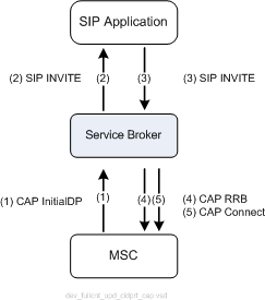
To provide a full call control, the application implements a SIP B2BUA. The application receives the SIP INVITE message sent by Service Broker and creates a new SIP dialog by sending a new SIP INVITE towards Service Broker.
Service Broker receives the SIP INVITE and sends a CAP Continue or a CAP Connect operation accompanied by a CAP RequestReportBCSEvent operation.
The CAP RequestReportBCSEvent operation instructs the MSC to monitor the call for call related events (for example O_Busy or O_No_Answer) and send notifications to Service Broker when an event is detected.
Service Broker sets the specific events to be monitored in the CAP RequestReportBCSEvent operation as defined in the Service Broker configuration.
Note:
Service Broker enables the application to specify events to be monitored, and by doing this, to overwrite the Service Broker configuration. For more information, see "Controlling the EDPs Arming".The following sections describe various call control capabilities. To provide each of the call control capabilities defined below, the application must follow relevant instructions described in the following sections.
A full control application needs to propagate the SDP which is provided by Service Broker, back-to-back. Figure 2-5 shows how the SDP is handled during the call initiation phase.
Figure 2-6 shows how the SDP is handled during the call answering phase.
Table 2-11 Handling the SIP Route Header: Applicable CAP Phases
| CAP 1 | CAP 2 | CAP 3 | CAP 4 |
|---|---|---|---|
|
YES |
YES |
YES |
YES |
The SIP Route header is defined in RFC 3323. A SIP full call control application implemented over the Service Broker has to follow the loose-routing mechanism defined in RFC 3261.
Figure 2-7 demonstrates the loose-routing mechanism.
Table 2-12 Updating the Called Party Number: Applicable CAP Phases
| CAP 1 | CAP 2 | CAP 3 | CAP 4 |
|---|---|---|---|
|
YES |
YES |
YES |
YES |
To update the called party number, application sets the SIP INVITE which is sent to Service Broker, to a new destination address. The new destination address is set in the user part of the RequestURI header. This makes Service Broker to respond to the CAP InitialDP with a CAP Connect operation.
Figure 2-8 shows the high level architecture for a full control application that updates the called party number.
Figure 2-8 Architecture for Updating the Called Party Number by a Full Call Control Application over a SIP Network

Figure 2-9 shows the same application as shown on Figure 2-8. However, on Figure 2-9, the application provides the same functionality over a CAP network using Service Broker.
Figure 2-9 Architecture for Updating the Called Party Number by a Full Call Control Application over a CAP Network Using Service Broker

Figure 2-10 and Figure 2-11 show the detailed sequence diagram for a full control application that updates the called party number.
Service Broker creates the CAP Connect operation based on the information received in the SIP INVITE, which is sent by the application. Table 2-13 shows the content of the CAP Connect operation as set by Service Broker.
Table 2-13 Service Broker Maps SIP INVITE to CAP Connect Operation
| CAP Connect | Source |
|---|---|
|
DestinationRoutingAddress :: AddressSignal |
INVITE :: Request-URI :: user part |
|
DestinationRoutingAddress :: NatureOfAddress indicator |
INVITE :: Request-URI :: noa token For more information on the noa token, see "Exposing Nature of Address" and "Updating the Nature of Address". |
|
DestinationRoutingAddress :: InternalNetwork NumberIndicator |
Service Broker configuration |
|
DestinationRoutingAddress :: NumberingPlan Indicator |
Service Broker configuration |
Table 2-14 Leaving the Called Party Number Unmodified: Applicable CAP Phases
| CAP 1 | CAP 2 | CAP 3 | CAP 4 |
|---|---|---|---|
|
YES |
YES |
YES |
YES |
To leave the called party number unmodified, the application sets the SIP INVITE, which is sent to Service Broker, to the address provided in the SIP INVITE message received from Service Broker.
This procedure is done by copying the user part of the Request-URI of the received SIP INVITE and pasting it into the SIP INVITE sent to Service Broker. This makes Service Broker to respond to InitialDP with a CAP Continue operation.
Table 2-15 Updating the Nature of Address: Applicable CAP Phases
| CAP 1 | CAP 2 | CAP 3 | CAP 4 |
|---|---|---|---|
|
YES |
YES |
YES |
YES |
To update the nature of address of a call party, the application sets the noa token in the SIP INVITE message, which is sent to Service Broker, to the required value as follows:
To update the called party nature of address, the application sets the noa token in the Request-URI header to the required value.
Figure 2-12 shows an example in which the application updates the called party nature of address. This example assumes that the CalledPartyNumber in CAP InitialDP is set with NatureOfAddress of type “national”. The application updates the called party nature of address and sets it to "unknown". This causes Service Broker to set the DestinationRoutingAddress in the CAP Connect operation to NatureOfAddress of type “unknown”.
Note:
In the example shown on Figure 2-12, although the application does not update the called party number, Service Broker uses CAP Connect rather than CAP Continue. This is done because the Connect operation enables Service Broker to update the called party nature of address towards the MSC. CAP Connect is set to the called party number as received from the CAP InitialDP operation.For more information on tNOA token, see "Invoking a SIP Application".
Table 2-16 Controlling the EDPs Arming: Applicable CAP Phases
| CAP 1 | CAP 2 | CAP 3 | CAP 4 |
|---|---|---|---|
|
YES |
YES |
YES |
YES |
As described in "Developing a Full Call Control Application", when Service Broker receives a SIP INVITE message, which is sent by a full call control application, Service Broker sends a CAP Continue or a CAP Connect operation accompanied by a CAP RequestReportBCSEvent operation.
The specific events to be monitored are set in the CAP RequestReportBCSEvent operation as defined in the Service Broker configuration.
In some cases, it is required that an application dynamically controls the events that Service Broker arms for a given call, that is to define the CAP EDPs set by Service Broker in the CAP RRBCSM operation.
To control the events that Service Broker arms in the RequestReportBCSEvent operation, the application sends a SIP INFO message prior to the SIP INVITE. The SIP INFO is sent through the SIP dialog created by Service Broker and contains a XER representation of the CAP RequestReportBCSEvent operation.
Figure 2-13 shows the high level architecture for a full control application that controls the DPs armed by Service Broker.
Table 2-17 Receiving Call Events Notifications: Applicable CAP Phases
| CAP 1 | CAP 2 | CAP 3 | CAP 4 |
|---|---|---|---|
|
YES |
YES |
YES |
YES |
Service Broker notifies a full call control application about encountered call-related events. For each call event encountered at the MSC and reported to Service Broker, Service Broker notifies the application using a corresponding SIP message as described in Table 2-18.
Notes to Table 2-18:
RouteSelectFailure events are applicable for originating calls only.
The table is applicable for both originating and terminating BCSM. For example, Service Broker uses SIP 486 Busy Here to notify the application about oCalledPartyBusy in an originating call and for tBusy in a terminating call.
If a Disconnect event is reported by the calling party, Service Broker sends a SIP BYE message through the dialog created by Service Broker. If a Disconnect event is reported by the calling party, Service Broker sends a SIP BYE message through the dialog created by the application.
For the DPs reported using SIP INFO, Service Broker sets the SIP INFO with a XER representation of the corresponding CAP EventReportBCSM operation.
Table 2-18 provides the full EDP list supported in CAP 4. Earlier CAP phases support only part of the EDPs listed in the table.
Table 2-18 Event Notifications
| CAP event | SIP message |
|---|---|
|
Route Select Failure |
410 Gone |
|
Busy |
486 Busy Here |
|
No Answer |
480 Temporary Unavailable |
|
Term Seized / Call Accepted |
180 Ringing |
|
Answer |
200 OK |
|
Disconnect |
BYE |
|
Abandon |
CANCEL |
To confirm notification and enable Service Broker to instruct the MSC to continue call processing at event notification, the application propagates the received SIP message back-to-back.
Note::
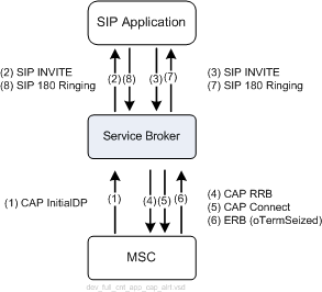
Call processing is suspended by the MSC when an event armed as EDP-R is encountered. When EDP-R is reported to Service Broker, MSC requests Service Broker instructions for call processing.Figure 2-14 shows a full control application in the call initiation process. When the called party is alerted, the application receives a SIP 180 Ringing message and propagate it back-to-back.
When the called party answers the call, the application receives a SIP 200 OK and again propagates this message back-to-back towards the initiating side.
Figure 2-15 shows a full control application in the call answering phase.
Finally, when the called party (or in another scenario, the calling party) disconnects the call, the application receives a SIP BYE and propagates it towards the initiating side as shown on Figure 2-16.
Figure 2-17, Figure 2-18, and Figure 2-19 show the same application as shown on Figure 2-14 and Figure 2-16. However, the application below provides the same functionality over a CAP network using Service Broker.
Figure 2-17 Architecture for Initiating a Call by a Full Control Application over a CAP Network Using Service Broker (Alerting Phase)

To terminate a call, the application sends a SIP BYE request towards Service Broker. The BYE request is sent on both active dialogs, that is the dialog created by Service Broker and the dialog created by the application.
Service Broker uses the BYE request to terminate the CAP dialog towards MSC using a CAP ReleaseCall operation.
Figure 2-20 shows architecture for a full control application terminating a call.
Figure 2-21 shows the same application as shown on Figure 2-20. However, on Figure 2-21, the application provides the same functionality over a CAP network using Service Broker.
Service Broker may respond towards the application with a SIP error in case an application request cannot be fulfilled or in other error cases as defined in Table 2-19.
| SIP Error | Description |
|---|---|
|
405 Method Not Allowed |
Sent by Service Broker in case the application requests a call control operation which is not legal in the current moment on the CAP interface |
|
403 Forbidden |
Sent by Service Broker in case the application requests a call control operation which is not supported by the specific CAP interface |
|
415 Unsupported Media Type |
Sent by Service Broker in case the application provides a non-supported SDP |
To reject a call, the application responds to the SIP INVITE with a SIP error response (for example, SIP 404 Not Found). When Service Broker receives the SIP error response, Service Broker performs one of the following actions:
Instructs the MSC to terminate the call by sending a CAP ReleaseCall operation
Instructs the MSC to allow the call to continue by sending a CAP Continue operation
Service Broker determines the action to be performed based on its configuration.
Figure 2-22 shows the high level architecture for a full control application that terminates a call.
Note:
The figures below shows an example in which the application uses SIP 404 Not Found to reject the call. In practice, applications are not limited to a specific SIP error response.Figure 2-23 shows the same application as shown on Figure 2-22. However, on Figure 2-23, the application provides the same functionality over a CAP network using Service Broker.
Service Broker uses the SIP error response sent by the application to set the cause parameter in the CAP ReleaseCall operation.
To instruct the Service Broker to set the ReleaseCall operation to a specific cause value, the application uses the corresponding SIP error response as defined in Table 2–22.