7 Integration With Mediator Service Components in the Oracle SOA Suite
This chapter describes integration with Mediator service components in the Oracle SOA Suite. It contains the following topics:
The scenarios shown in this chapter require the following prerequisites.
The following are installation and configuration requirements:
-
Oracle Application Adapter for SAP R/3 must be installed on Oracle WebLogic Server.
-
SAP must be configured for inbound and outbound processing. For more information, see Appendix A, "Understanding the SAP System Role in Remote Processing".
The examples in this chapter present the configuration steps necessary for demonstrating service and event integration with SAP. Prior to using this material, you must be familiar with the following:
-
How to configure Oracle Application Adapter for SAP R/3 for services and events. For more information, see Chapter 4, "Configuring Oracle Application Adapter for SAP R/3".
-
How to configure Oracle JDeveloper. For more information, see Chapter 6, "Integration With BPEL Service Components in the Oracle SOA Suite".
Overview of Mediator Integration
Mediator provides a comprehensive application integration framework. Oracle Application Adapter for SAP R/3 used with Mediator enables you to seamlessly integrate enterprise software, eliminating custom code. Functional modeling, as opposed to custom coding solutions, allows for software reuse and reduces the complexity and management challenges that arise over the software lifecycle. This integration model consists of two components--high-level integration logic and low-level platform services.
Adapter integration with Oracle Mediator is a two-step process:
-
Design Time: Oracle Application Adapter for SAP R/3 is configured in Application Explorer for services and events, as described in Chapter 4, "Configuring Oracle Application Adapter for SAP R/3". Integration logic is modeled in Mediator.
-
Runtime: The underlying platform treats this metadata as run-time instructions to enable the communication between participating applications.
Configuring a New Application Server Connection
For more information on how to configure a new Application Server connection in Oracle JDeveloper, see Configuring a New Application Server Connection.
Configuring a Mediator Outbound Process
The following example describes how to configure a Mediator outbound process to your SAP system, using a Mediator project in Oracle JDeveloper.
Samples have been provided for this use case scenario under the etc/sample folder of the Application Adapters installation.
Before you design a Mediator outbound process, you must generate the respective WSDL file using Application Explorer. For more information, see "Generating WSDL for Request/Response Service".
Creating an Empty Composite for SOA
Perform the following steps to create an empty composite for SOA:
-
Create a new SOA application.
-
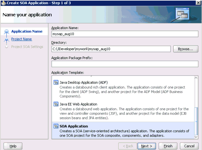
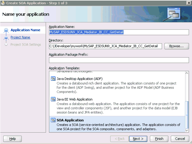
Enter a name for the new SOA Application and click Next, as shown in Figure 7-1.
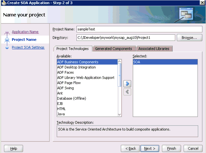
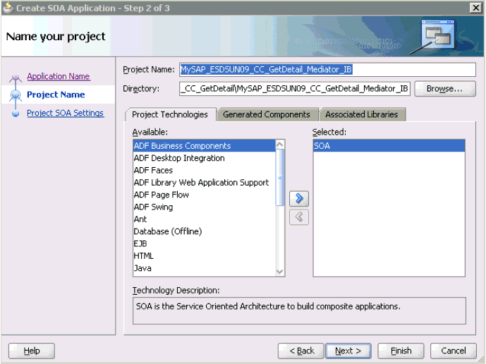
The Name your project page is displayed, as shown in Figure 7-2.
-
Enter a project name (for example, sampleTest) and click Next.
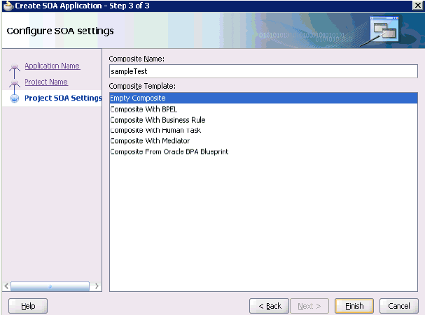
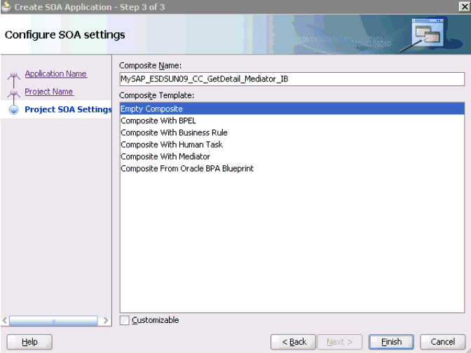
The Configure SOA settings page is displayed, as shown in Figure 7-3.
-
From the Composite Template list, select Empty Composite and click Finish.
Defining a Mediator Outbound Process
This section describes how to define a Mediator outbound process, which consists of the following stages:
-
Configuring a Third Party Adapter Service Component
-
Configuring an Outbound Mediator Process Component
-
Configuring the Routing Rules
Configuring a Third Party Adapter Service Component
Perform the following steps to create a third party adapter service component:
-
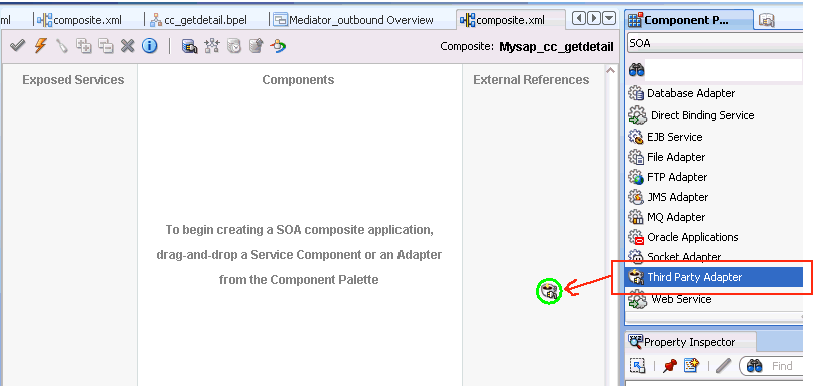
Drag and drop the Third Party Adapter component from the Service Adapters pane to the External References pane, as shown in Figure 7-4.
The Create Third Party Adapter Service dialog is displayed, as shown in Figure 7-5.
Figure 7-5 Create Third Party Adapter Service Dialog
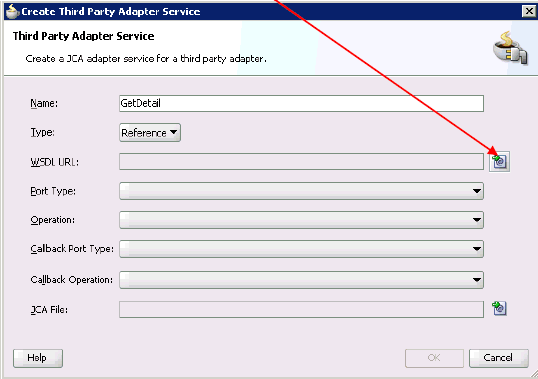
Description of "Figure 7-5 Create Third Party Adapter Service Dialog"
-
Enter a name for the third party adapter service.
-
Ensure that Reference is selected from the Type drop-down list (default).
-
Click the Find existing WSDLs icon, which is located to the right of the WSDL URL field.
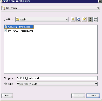
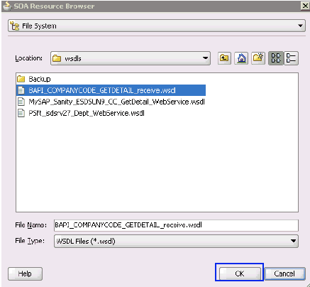
The SOA Resource Browser dialog is displayed, as shown in Figure 7-6.
-
Browse and select an outbound WSDL file from the following directory:
<ADAPTER_HOME>\soa\thirdparty\ApplicationAdapters\wsdls -
Click OK.
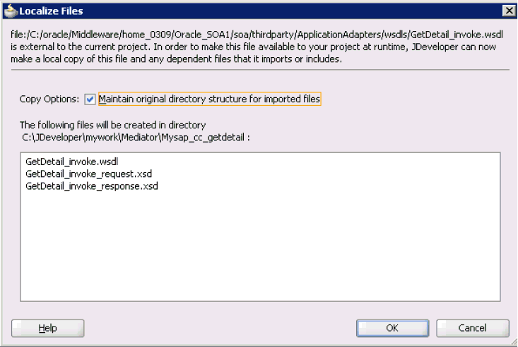
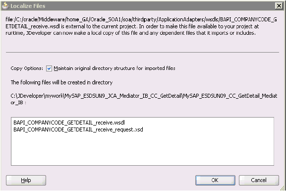
The Localize Files dialog is displayed, as shown in Figure 7-7.
-
Click OK.
The outbound WSDL file and associated request and response XML schema files (.xsd) are imported to the project folder that has been created.
You are returned to the Create Third Party Adapter Service dialog, as shown in Figure 7-8.
Figure 7-8 Create Third Party Adapter Service Dialog
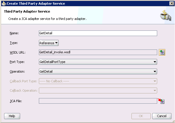
Description of "Figure 7-8 Create Third Party Adapter Service Dialog"
-
Click the Find JCA file icon, which is located to the right of the JCA File field.
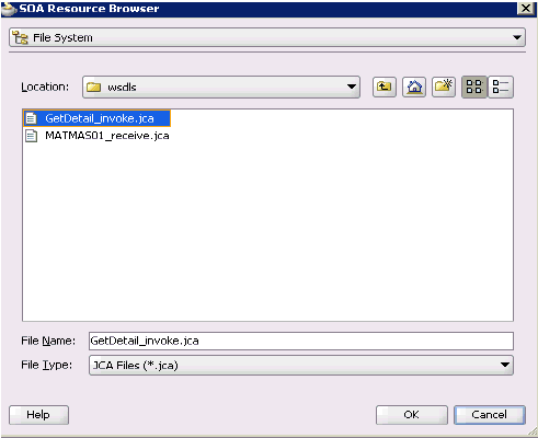
The SOA Resource Browser dialog is displayed, as shown in Figure 7-9.
-
Browse and select the JCA properties file from the following directory:
<ADAPTER_HOME>\soa\thirdparty\ApplicationAdapters\wsdls -
Click OK.
A Copy File confirmation message is displayed, as shown in Figure 7-10.
Figure 7-10 Copy File Confirmation Message
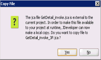
Description of "Figure 7-10 Copy File Confirmation Message"
-
Click Yes.
A copy of the JCA properties file is made in the project folder.
You are returned to the Create Third Party Adapter Service dialog, as shown in Figure 7-11.
Figure 7-11 Create Third Party Adapter Service Dialog
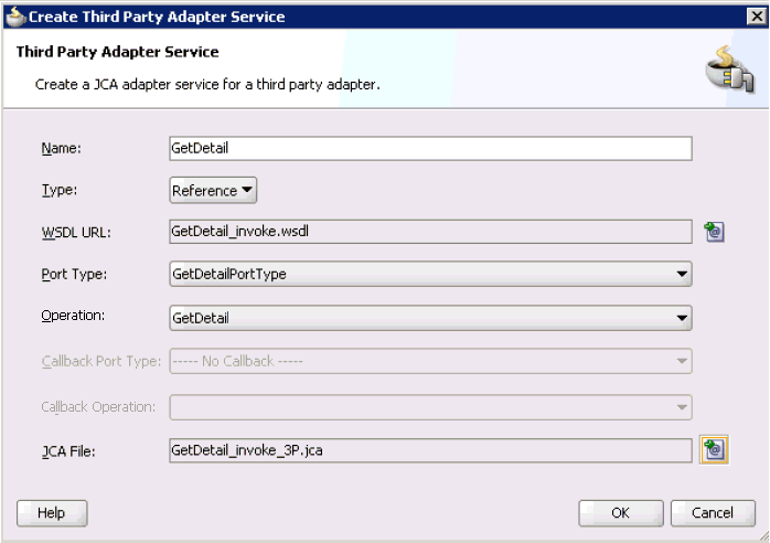
Description of "Figure 7-11 Create Third Party Adapter Service Dialog"
-
Click OK.
The third party adapter service component (GetDetail) is created in the External References pane, as shown in Figure 7-12.
Figure 7-12 Third Party Adapter Service Component (Get Detail)
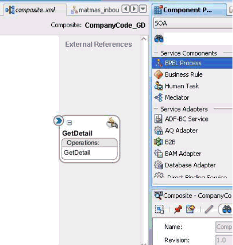
Description of "Figure 7-12 Third Party Adapter Service Component (Get Detail)"
You are now ready to configure an outbound Mediator process component.
Configuring an Outbound Mediator Process Component
Perform the following steps to configure an outbound Mediator process component:
-
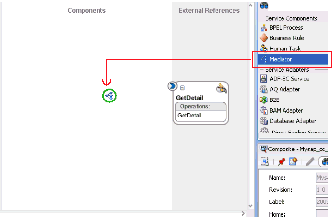
Drag and drop the Mediator Process component from the Service Components pane to the Components pane, as shown in Figure 7-13.
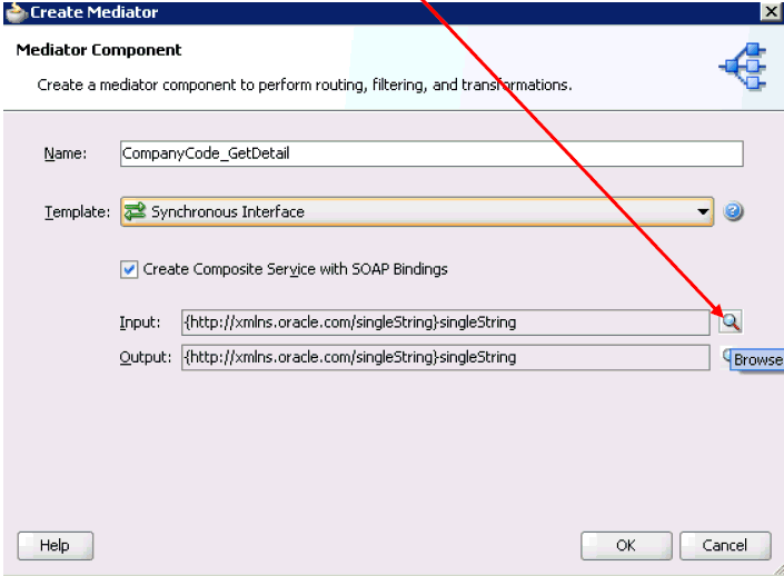
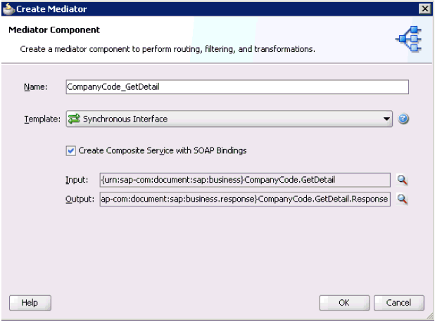
The Create Mediator dialog is displayed, as shown in Figure 7-14.
-
In the Name field, enter a name to identify the new outbound Mediator process component (for example, CompanyCode_GetDetail).
-
From the Template drop-down list, select Synchronous Interface.
-
Click the Browse icon, which is located to the right of the Input field to select the associated XML request schema file.
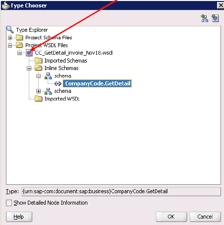
The Type Chooser dialog is displayed, as shown in Figure 7-15.
-
Expand Project WSDL Files, CC_GetDetail_invoke_Nov18.wsdl, Inline Schemas, and select CompanyCode.GetDetail.
-
Click OK.
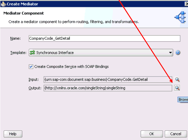
You are returned to the Create Mediator dialog, as shown in Figure 7-16.
-
Click the Browse icon, which is located to the right of the Output field to select the associated XML response schema file.
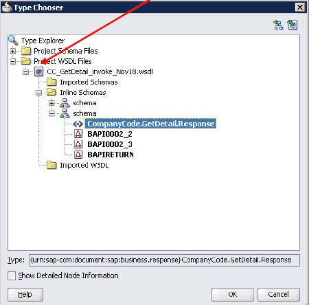
The Type Chooser dialog is displayed, as shown in Figure 7-17.
-
Expand Project WSDL Files, CC_GetDetail_invoke_Nov18.wsdl, Inline Schemas, schema, and select CompanyCode.GetDetailResponse.
-
Click OK.
You are returned to the Create Mediator dialog, as shown in Figure 7-18.
-
Click OK.
-
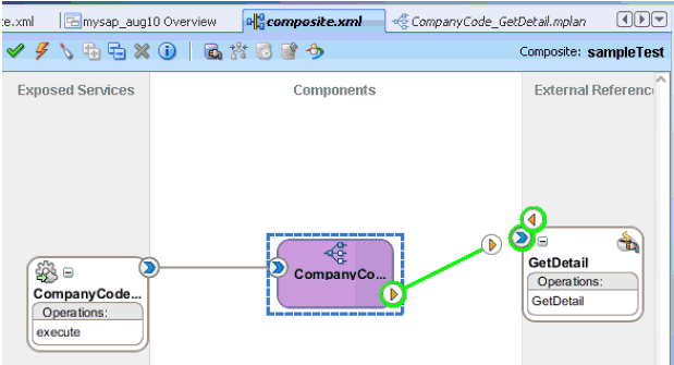
Create a connection between the outbound Mediator process component (CompanyCode_ GetDetail) and the third party adapter service component (GetDetail), as shown in Figure 7-19.
You are now ready to configure the routing rules.
Perform the following steps to configure routing rules for the Mediator outbound process component:
-
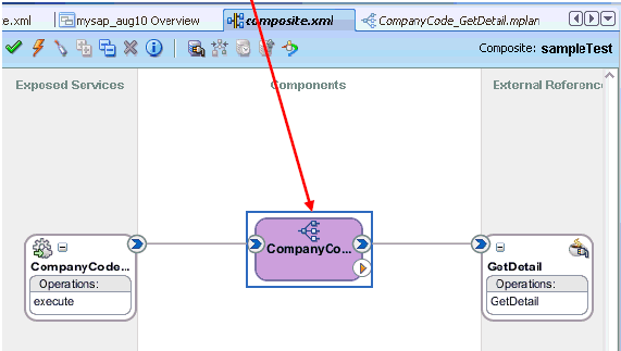
Double-click the outbound Mediator process component (CompanyCode_ GetDetail) in the Components pane, as shown in Figure 7-20.
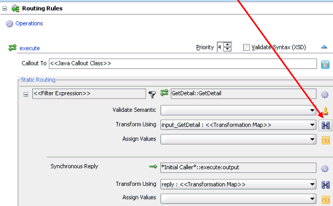
The Routing Rules dialog is displayed, as shown in Figure 7-21.
-
In the <<Filter Expression>> area, click the icon to the right of the Transform Using field.
The Request Transformation Map dialog is displayed, as shown in Figure 7-22.
Figure 7-22 Request Transformation Map Dialog

Description of "Figure 7-22 Request Transformation Map Dialog"
-
Select the Create New Mapper File option and click OK.
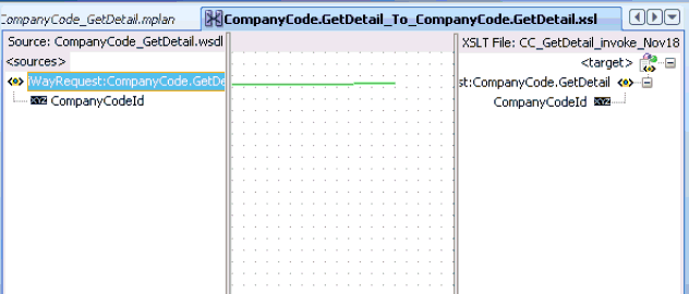
The following mapping page is displayed, as shown in Figure 7-23.
-
Map the iWayRequest:CompanyCode.GetDetail source element to the iWayRequest:CompanyCode.GetDetail target element.
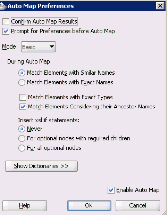
The Auto Map Preferences dialog is displayed, as shown in Figure 7-24.
-
Retain the default values and click OK.
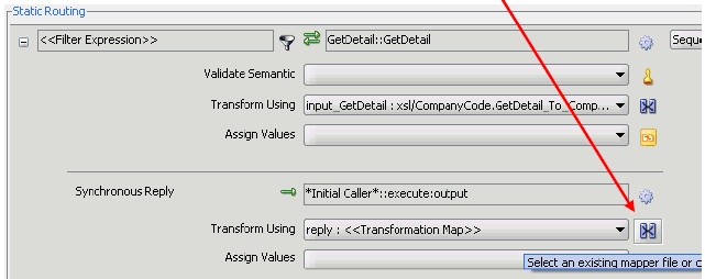
You are returned to the Routing Rules dialog, as shown in Figure 7-25.
-
In the Synchronous Reply area, click the icon to the right of the Transform Using field.
The Reply Transformation Map dialog is displayed, as shown in Figure 7-26.
Figure 7-26 Reply Transformation Map Dialog

Description of "Figure 7-26 Reply Transformation Map Dialog"
-
Select the Create New Mapper File option and click OK.
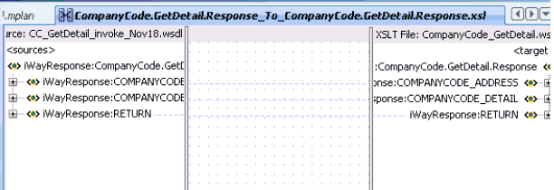
A mapping page is displayed, as shown in Figure 7-27.
-
Map the iWayResponse:CompanyCode.GetDetail.Response source element to the iWayResponse:CompanyCode.GetDetail.Response target element.
The Auto Map Preferences dialog is displayed, as shown in Figure 7-28.
-
Retain the default values and click OK.
The mapping is completed, as shown in Figure 7-29.
-
Click the Save All icon in the menu bar to save the new outbound Mediator process component that was configured.
You are now ready to deploy the Mediator outbound process.
Deploying the Mediator Outbound Process
Perform the following steps to deploy the Mediator outbound process.
-
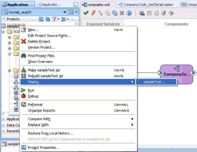
Right-click the project name in the left pane (for example, sampleTest), select Deploy from the context menu, and click sampleTest, as shown in Figure 7-30.
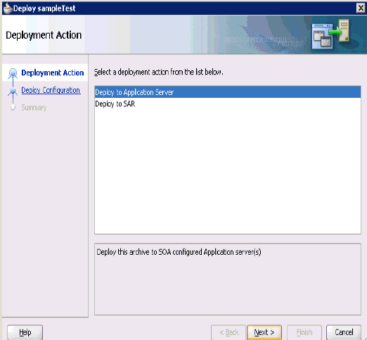
The Deployment Action page is displayed, as shon in Figure 7-31.
-
Ensure that Deploy to Application Server is selected.
-
Click Next.
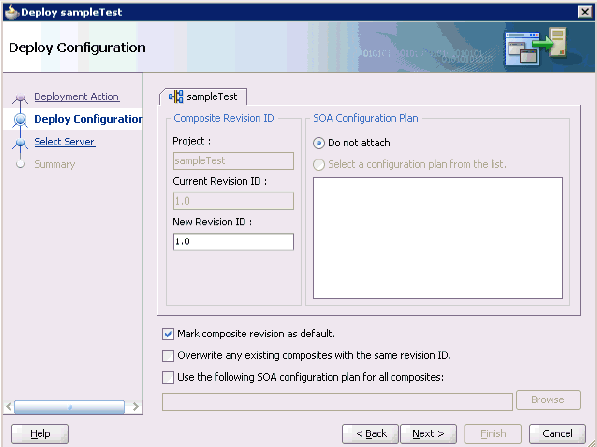
The Deploy Configuration page is displayed, as shown in Figure 7-32.
-
Leave the default values selected and click Next.
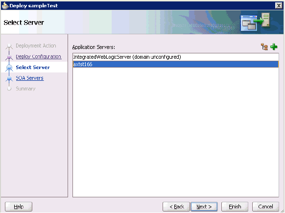
The Select Server page is displayed, as shown in Figure 7-33.
-
Select an available application server that was configured and click Next.
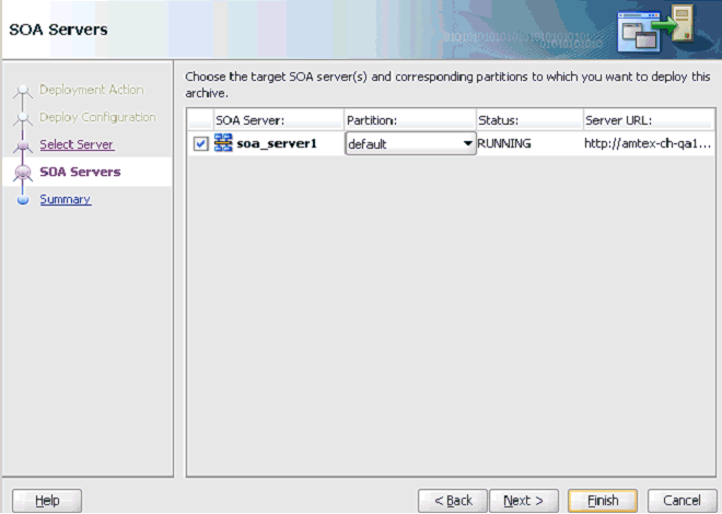
The SOA Servers page is displayed, as shown in Figure 7-34.
-
Select a target SOA server and click Next.
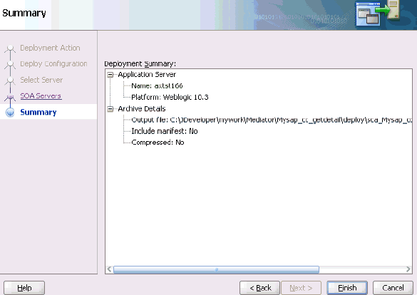
The Summary page is displayed, as shown in Figure 7-35.
-
Review and verify all the available deployment information for your project and click Finish.
The process is deployed successfully, as shown in Figure 7-36.
Figure 7-36 Successful Deployment Message

Description of "Figure 7-36 Successful Deployment Message"
Invoking the Input XML Document in the Oracle Enterprise Manager Console
Perform the following steps to invoke the input XML document in the Oracle Enterprise Manager console.
-
Logon to the Oracle Enterprise Manager console, as shown in Figure 7-37.
Figure 7-37 Oracle Enterprise Manager Console
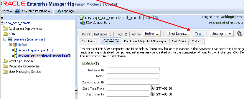
Description of "Figure 7-37 Oracle Enterprise Manager Console"
-
Expand your domain in the left pane followed by the SOA folder.
-
Select an available project in the left pane.
-
Click Test.
-
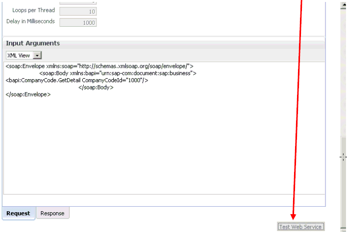
Click the Request tab, as shown in Figure 7-38.
-
Provide an appropriate input value in the Input Arguments area and click Test Web Service.
The output response is received in the Oracle Enterprise Manager console, as shown in Figure 7-39.
Figure 7-39 Oracle Enterprise Manager Console
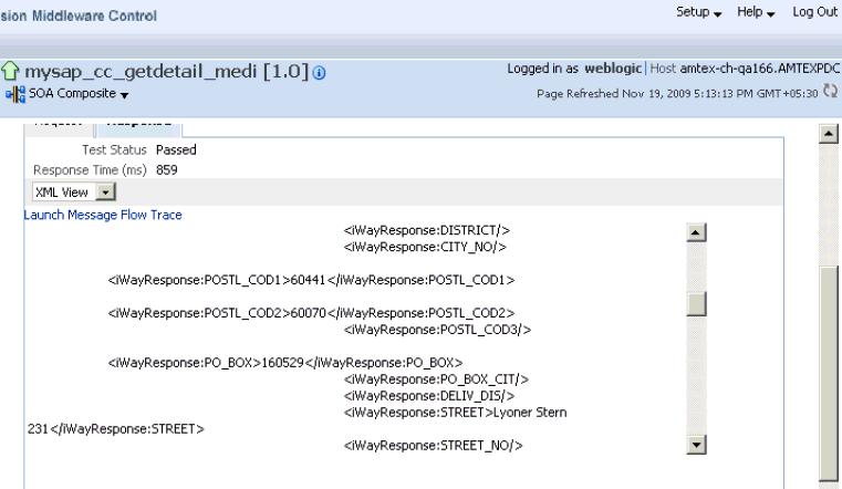
Description of "Figure 7-39 Oracle Enterprise Manager Console"
Configuring a Mediator Inbound Process
The following example describes how to configure a Mediator inbound process to your SAP system, using a Mediator project in Oracle JDeveloper.
Samples have been provided for this use case scenario under the etc/sample folder of the Application Adapters installation.
Before you design a Mediator inbound process, you must generate the respective WSDL file using Application Explorer. For more information, see "Generating WSDL for Event Integration".
Creating an Empty Composite for SOA
Perform the following steps to create an empty composite for SOA:
-
Create a new SOA application.
-
Enter a name for the new SOA Application and click Next, as shown in Figure 7-40.
The Name your project page is displayed, as shown in Figure 7-41.
-
Enter a project name and click Next.
The Configure SOA settings page is displayed, as shown in Figure 7-42.
-
From the Composite Template list, select Empty Composite and click Finish.
Defining a Mediator Inbound Process
This section describes how to define a Mediator inbound process, which consists of the following stages:
-
Configuring a Third Party Adapter Service Component
-
Configuring an Inbound Mediator Process Component With a File Adapter
-
Configuring the Routing Rules
Configuring a Third Party Adapter Service Component
Perform the following steps to create a third party adapter service component:
-
Drag and drop the Third Party Adapter component from the Service Adapters pane to the Exposed Services pane, as shown in Figure 7-43.
Figure 7-43 Third Party Adapter Component
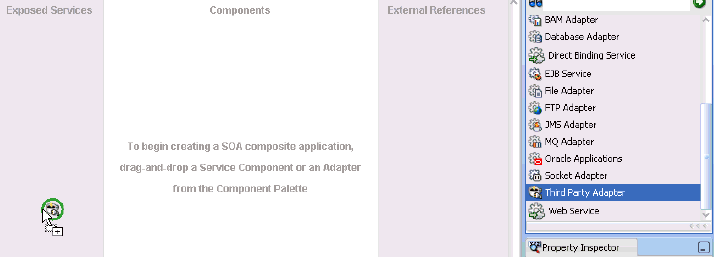
Description of "Figure 7-43 Third Party Adapter Component"
The Create Third Party Adapter Service dialog is displayed, as shown in Figure 7-44.
Figure 7-44 Create Third Party Adapter Service Dialog
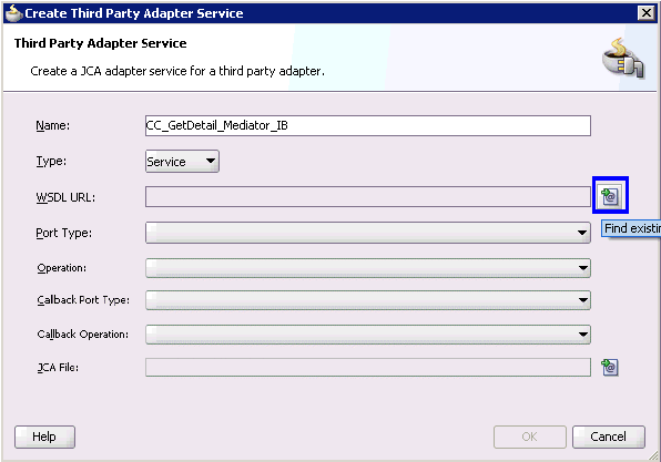
Description of "Figure 7-44 Create Third Party Adapter Service Dialog"
-
Enter a name for the third party adapter service (for example, CC_GetDetail_Mediator_IB).
-
Ensure that Service is selected from the Type drop-down list (default).
-
Click the Find existing WSDLs icon, which is located to the right of the WSDL URL field.
The SOA Resource Browser dialog is displayed, as shown in Figure 7-45.
-
Browse and select an inbound WSDL file from the following directory:
<ADAPTER_HOME>\soa\thirdparty\ApplicationAdapters\wsdls -
Click OK.
The Localize Files dialog is displayed, as shown in Figure 7-46.
-
Click OK.
The inbound WSDL file and associated receive/request schema file (.xsd) are imported to the project folder that has been created.
You are returned to the Create Third Party Adapter Service dialog, as shown in Figure 7-47.
Figure 7-47 Create Third Party Adapter Service Dialog
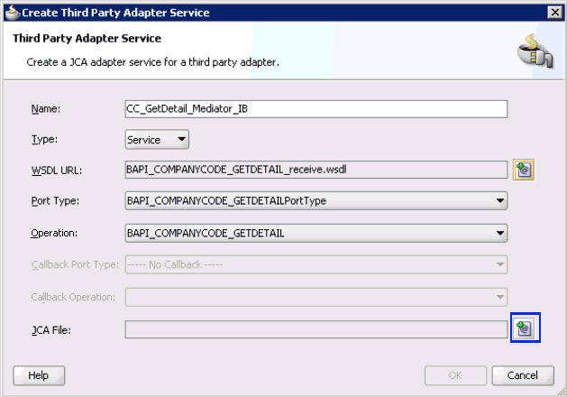
Description of "Figure 7-47 Create Third Party Adapter Service Dialog"
-
Click the Find JCA file icon, which is located to the right of the JCA File field.
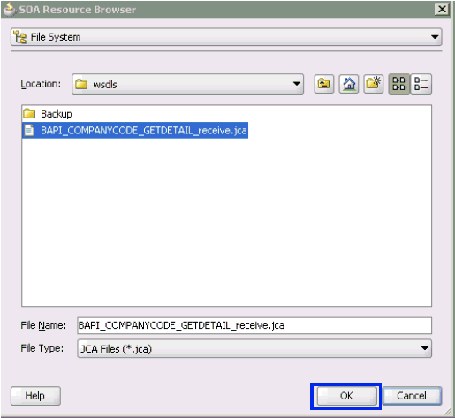
The SOA Resource Browser dialog is displayed, as shown in Figure 7-48.
-
Browse and select the JCA properties file from the following directory:
<ADAPTER_HOME>\soa\thirdparty\ApplicationAdapters\wsdls -
Click OK.
The following message is displayed, as shown in Figure 7-49.
Figure 7-49 Copy File Confirmation Message
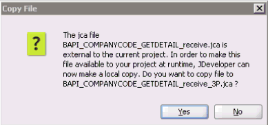
Description of "Figure 7-49 Copy File Confirmation Message"
-
Click Yes.
A copy of the JCA properties file is made in the project folder.
You are returned to the Create Third Party Adapter Service dialog, as shown in Figure 7-50.
Figure 7-50 Create Third Party Adapter Service Dialog
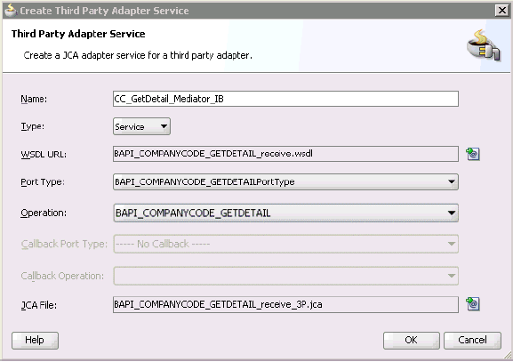
Description of "Figure 7-50 Create Third Party Adapter Service Dialog"
-
Click OK.
The third party adapter service component (CC_GetDetail_Mediator_IB) is created in the Exposed Services pane, as shown in Figure 7-51.
Figure 7-51 Third Party Adapter Service Component
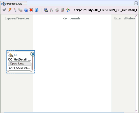
Description of "Figure 7-51 Third Party Adapter Service Component"
You are now ready to configure an inbound Mediator process component.
Configuring an Inbound Mediator Process Component With a File Adapter
Perform the following steps to configure an inbound Mediator process component with a File adapter.
-
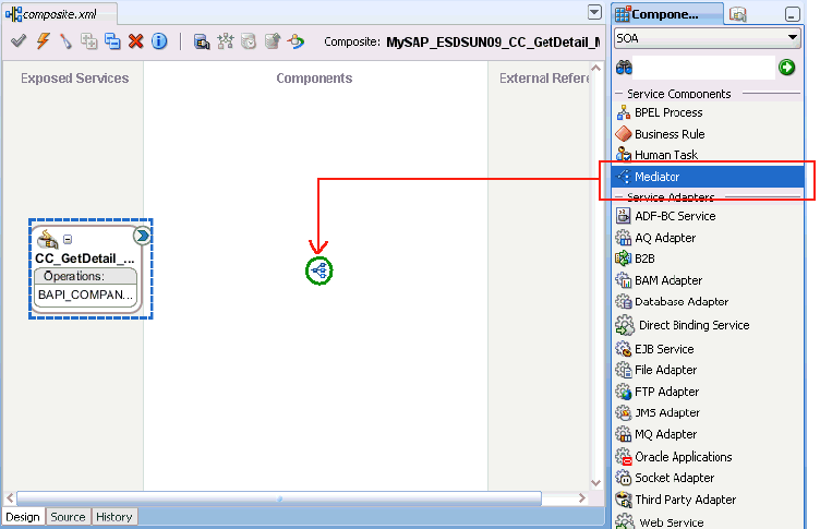
Drag and drop the Mediator Process component from the Service Components pane to the Components pane, as shown in Figure 7-52.
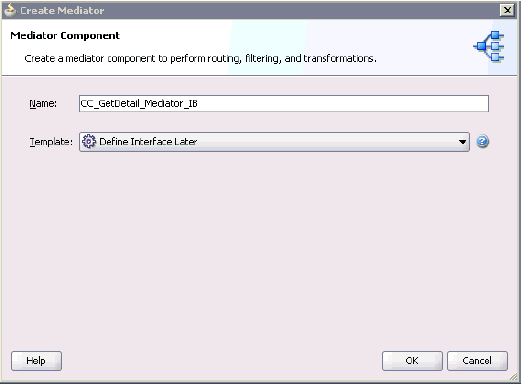
The Create Mediator dialog is displayed, as shown in Figure 7-53.
-
In the Name field, enter a name to identify the new inbound Mediator process component (for example, CC_GetDetail_Mediator_IB).
-
From the Template drop-down list, select Define Interface Later.
-
Click the OK.
The new Mediator process component is added to the Components pane, as shown in Figure 7-54.
-
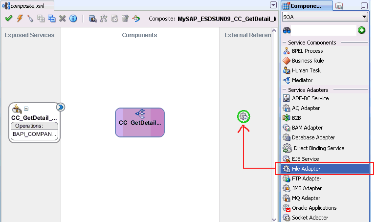
Drag and drop the File Adapter component from the Service Adapters pane to the External References pane.
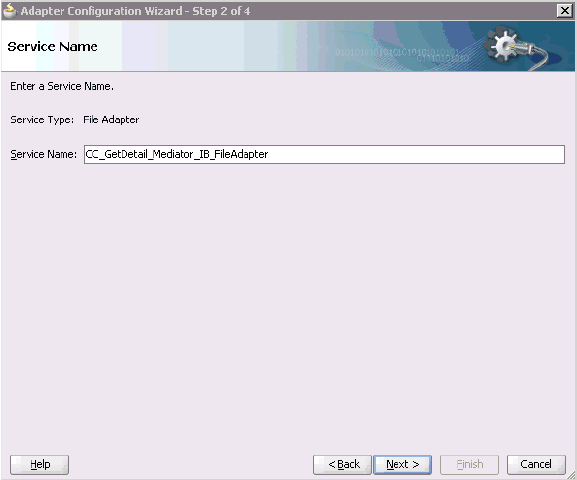
The Adapter Configuration Wizard is displayed, showing the Service Name page, as shown in Figure 7-55.
-
Type a name for the new File adapter in the Service Name field and click Next.
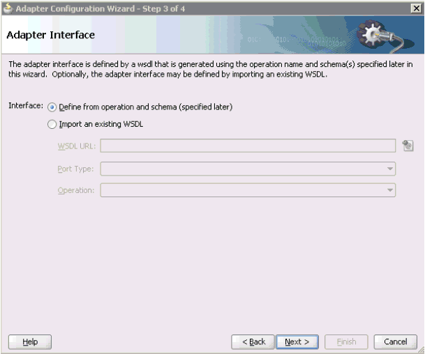
The Adapter Interface page is displayed, as shown in Figure 7-56.
-
Ensure that the Define from operation and schema (specified later) option is selected.
-
Click Next.
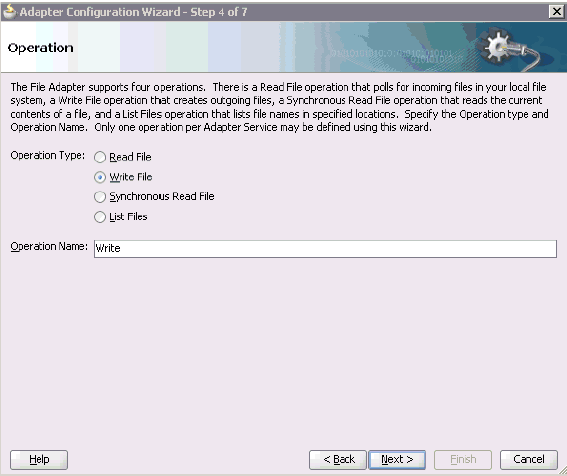
The Operation page is displayed, as shown in Figure 7-57.
-
Select Write File from the list of Operation Type options and specify an Operation Name (for example, Write).
-
Click Next.
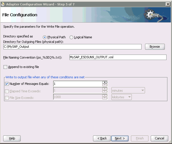
The File Configuration page is displayed, as shown in Figure 7-58.
-
Specify a location on your file system where the output file is written.
-
In the File Naming Convention field, specify a name for the output file.
-
Click Next.
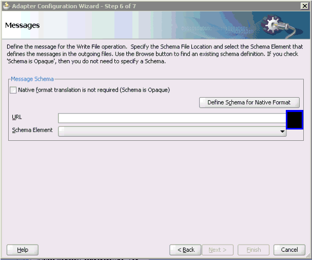
The Messages page is displayed, as shown in Figure 7-59.
-
Click Browse, which is located to the right of the URL field.
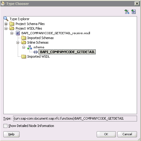
The Type Chooser dialog is displayed, as shown in Figure 7-60.
-
Expand Project WSDL Files, BAPI_COMPANYCODE_GETDETAIL_receive.wsdl, Inline Schemas, and schema.
-
Select the available schema (for example, BAPI.CompanyCode.GetDetail)
-
Click OK.
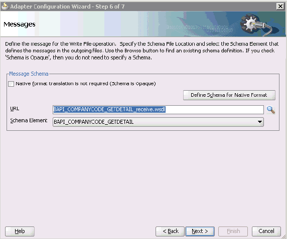
You are returned to the Messages page, as shown in Figure 7-61.
-
Click Next.
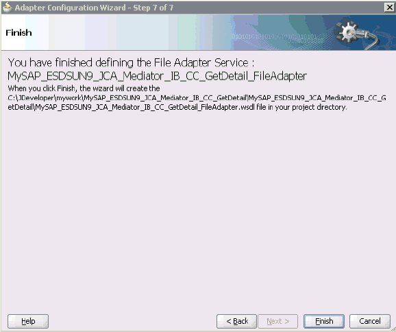
The Finish page is displayed, as shown in Figure 7-62.
-
Click Finish.
-
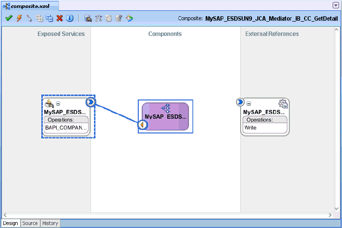
Create a connection between the inbound Mediator process component and the third party adapter service component, as shown in Figure 7-63.
-
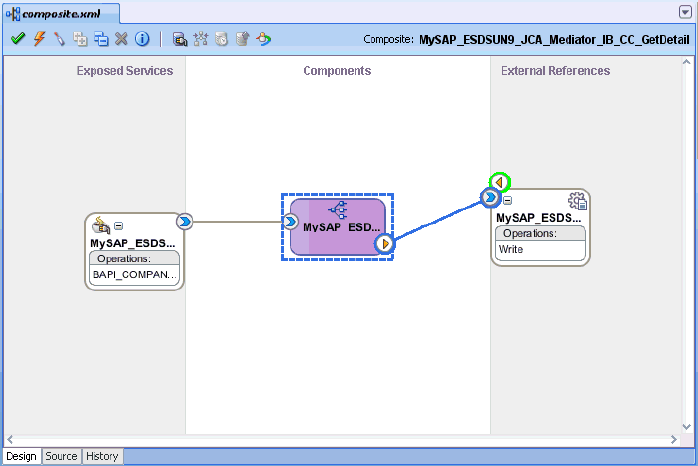
Create a connection between the inbound Mediator process component and the File adapter component, as shown in Figure 7-64.
You are now ready to configure the routing rules.
Perform the following steps to configure routing rules for the Mediator inbound process component:
-
Double-click the inbound Mediator process component in the Components page, as shown in Figure 7-65.
Figure 7-65 Inbound Mediator Process Component
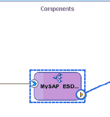
Description of "Figure 7-65 Inbound Mediator Process Component"
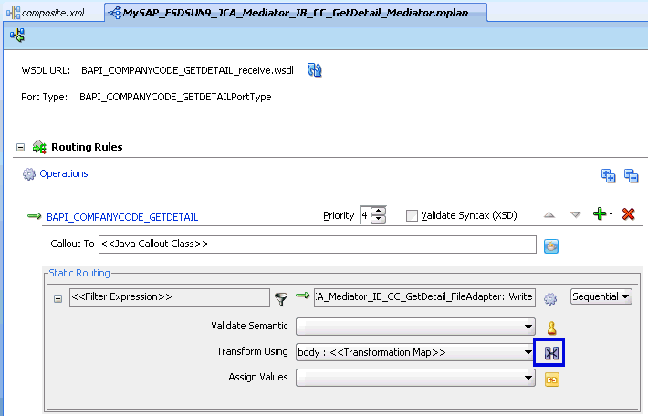
The Routing Rules dialog is displayed, as shown in Figure 7-66.
-
In the <<Filter Expression>> area, click the icon to the right of the Transform Using field.
The Request Transformation Map dialog is displayed, as shown in Figure 7-67.
Figure 7-67 Request Transformation Map Dialog

Description of "Figure 7-67 Request Transformation Map Dialog"
-
Select the Create New Mapper File option and click OK.
The mapping page is displayed, as shown in Figure 7-68.
-
Map the iWayEvent:BAPI_COMPANYCODE_GETDETAIL source element to the iWayEvent:BAPI_COMPANYCODE_GETDETAIL target element.
The Auto Map Preferences dialog is displayed, as shown in Figure 7-69.
-
Retain the default values and click OK.
You are returned to the Routing Rules dialog. The mapping is now complete.
-
Click the Save All icon in the menu bar to save the new inbound Mediator process component that was configured.
You are now ready to deploy the Mediator inbound process. You can follow the same procedure in "Deploying the BPEL Inbound Process".
Once event messages are triggered through SAP GUI, output XML is received in the location that was specified for the File adapter component. For more information on triggering events in SAP R/3, see "Triggering an Event in SAP R/3".
