8 Hardware and Provisioning Profiles
Deployment starts from configuring the hardware, installing the correct firmware, provisioning the OS, and applying the required patches. Enterprise Manager Ops Center deploys assets using deployment plans and the profiles that are included in the plans.
The following topics are covered in this section:
About Hardware and Provisioning Profiles
See Update Profiles and Creating a Software Deployment Plan for information about profiles that update software.
The work flow of an asset deployment can be captured and enacted in a highly repeatable fashion using deployment plans and the profiles included in the plans. Enterprise Manager Ops Center provides default profiles for configuring hardware asset types consistently. You can use the default profiles, make copies of the profile to edit, or create new ones.
The deployment is not only for servers with an OS installed but also for chassis, M-Series servers, and Oracle VM Server. The server deployment provides provisioning and updating operating systems, creating and provisioning logical domains.
Use hardware resource profiles to configure, install, or update systems. Use provisioning profiles to install an OS on physical or virtual servers. By applying the profile to multiple targets, you install the OS on multiple systems simultaneously. The profile contains all the attributes required for OS provisioning.
You can create profiles for different types of targets:
-
Oracle Solaris SPARC
-
Oracle Solaris x86
-
Oracle Linux
-
SUSE Linux
-
Oracle VM Server and its logical domains Although the profile defines the configuration parameters, the binding of the resources such as network and storage occur when you apply the profile.
See Managing Profiles for information about viewing and creating profiles.
Hardware Resource Profiles
The Enterprise Manager Ops Center software provides the following hardware profiles:
-
Service Processor – You can configure Service Processors, Chassis, and Dynamic System Domains.
-
RAID Controller – You can configure and update the hardware devices that can done only through the host OS. This profile provisions a reduced OS image along with the management pack on the target to configure RAID.
-
Dynamic System Domain – You can create domains on a M-series server.
You can use the default profiles, make copies of the profile to edit, or create new ones. Use the profiles in a deployment plan to configure your hardware assets.
Configuring a Service Processor
Use a deployment plan to configure the service processor on one or more servers. You can configure only unconfigured service processors, that is, a processor in its factory default state.
-
Connect the server hardware in its unconfigured state.
-
Use the Declare Unconfigured Asset action to include the service processor in the Enterprise Manager Ops Center environment.
-
For an M-Series server, verify that a user account with platadm privilege exists on the XSCF processor and is included in the profile.
-
For an M-Series server, verify that you can use ssh to log into the XSCF processor.
To Configure a Service Processor
-
Display the list of existing plans by performing one of the following:
-
Expand Plan Management, click Deployment Plans, then click Configure Service Processor. or
-
Expand the All Assets tree, select the service processor, then click Configure and Deploy Server in the Action pane. A list of existing plans is displayed. If no plans exist, create one using the procedure in Creating a Deployment Plan.
-
-
Select the plan you want to use. The details of the plan, including the profile it uses, are displayed. By default, the service processor are configured according to values in the profile without any interaction. The service processors of all target servers have the same password.
-
If you want to apply the plan but make some changes during the configuration, click the "Allow me to override any profile values" option. During the configuration, you can enter different values.
-
Click Apply Deployment Plan in the Actions pane. The Configure Service Processor wizard starts and displays a list of assets.
-
Select one or more servers and click Add To Target List. When you are finished, click Next. The Resource Assignment panel is displayed. At any time, you can click the Targets tab to review the selected servers.
-
Type the System Identifier, Contact, and Location. Click Next. If you selected more than one target, a list of all the targets is displayed, showing the same resource assignments for each target. Edit the resource assignments for any target that you want to identify uniquely. Click Next. The Summary page shows the values in the profile and the list of each target.
-
Review the Summary page and when you are ready to configure the service processors, click Apply. The configuration job is submitted. View the progress of the job by clicking the View Job Details icon in the Jobs pane.
Configuring a RAID Controller
Enterprise Manager Ops Center provides a default profile for configuring RAID controllers. Use this procedure to configure the RAID controller.
Note:
When you re-configure an existing RAID controller, all the data on the disk is lost.To Configure a RAID Controller
-
Expand Plan Management and click Deployment Plans.
-
Click Configure RAID. A list of existing plans is displayed. If no plans exist, create one using the procedure in Creating a Deployment Plan.
-
Select a plan.
-
Click Apply Deployment Plan in the Actions pane. The details of the plan, including the profile it uses, are displayed. By default, the RAID controller is configured according to values in the profile without any interaction.
-
If you want to apply the plan but make some changes during the configuration, click the "Allow me to override any profile values" option. During the configuration, you can enter different values.
-
Click Apply Deployment Plan in the Actions pane. The Configure RAID Controller wizard starts and displays a list of assets.
-
Select one or more servers and click Add To Target List. When you are finished, click Next. The Resource Assignment panel is displayed. At any time, you can click the Targets tab to review the selected servers.
-
Review the attributes of the RAID controller. Click Next. The Summary page shows the values in the profile and the list of targets.
-
Review the Summary page and when you are ready to configure the RAID controllers, click Apply. The configuration job is submitted. The plan configures the server's RAID controller, according to the profile. To view the progress of the job, click the View Job Details icon in the Jobs pane.
Creating a Dynamic System Domain
To create a Dynamic System Domain, you apply a deployment to an M-Series server. The plan includes the profile of the Dynamic System Domain.
To Create a Dynamic System Domain
-
Discover and manage an M-Series server.
-
Expand Plan Management and click Deployment Plans.
-
Click Create Dynamic System Domain. A list of existing plans is displayed. If no plans exist, create one using the procedure in Creating a Deployment Plan.
-
Select one of the deployment plans. The details of profiles in the plan are displayed in the center pane.
-
Click Apply Deployment Plan in the Actions pane.
-
Select the M-Series server. The plan creates the new domain, according to the profile you select. You can view the progress of the plan by clicking the View Job Details icon in the Jobs pane.
Creating a Service Processor Profile
Enterprise Manager Ops Center provides a default profile for configuring service processors. Use this procedure to create a new profile and, optionally, a deployment plan.
To Create a Service Processor Profile
-
Expand Plan Management and click Profiles and Policies.
-
Click Service Processor. A list of existing profiles is displayed.
-
Click Create Profile in the Actions pane. The Create Profile wizard starts.
-
Type a name to identify the profile. Although the maximum is 255 characters, a practical limit for display purposes is 20 characters. Type a description to explain the purpose of the profile. By default, creating a profile also creates a deployment plan with the new profile as its only step. If you prefer not to create a deployment plan from this profile at this time, click the checkbox to clear it.
-
In the Subtype field, select one of the types of service processors. If you choose the service processor for an M-Series server, you also choose the type of M-Series server. Click Next. The Specify Credentials pane is displayed.
-
Type a password for root access to the service processor and then re-enter the password to confirm. If you are configuring the service processors of M-series servers, enter the account name and password for the user account you created with platadm permissions.
Note:
When you use this profile, the service processors of all target servers have this password. -
The Specify DNS Setting pane provides the option of enabling Dynamic Name Service. To enable the service, click the Use DNS checkbox. The wizard displays fields for this service:
-
DNS Servers – Enter a comma-separated list of IP addresses for up three DNS server.
-
Search Path – Enter a comma-separated list of up to six DNS domain names.
-
Retries – Enter a value between 0 and 5 for the number of retries.
-
Timeout – Enter a value between 1-10 for the number of seconds to expire. Check the Auto DNS field, to enable auto DNS. Click Next.
-
-
In the Clocks and SNMP Settings pane, specify the time zone for the service processor. You have the option of also using NTP service. The default action is to use the proxy controller's date and time. To enable NTP service, click the checkbox and enter the IP address of at least one NTP server. Click Next.
-
If you are creating a configuration profile for an CMM SP or Server SP, review the Summary page. If you are creating a configuration profile for an M-series server's SP, define its network connections. Enter the IP address and netmask of the Domain to DSCP (Service Processor Communication Protocol) server. You can accept or change the displayed addresses for the active XSCFU ISN IP address, the standby XSCFU ISN IP address, and the ISN Netmask. You can choose to include the address of the duplicate LAN of the Service Processor XSCF, the LAN#1-XSCF. The primary LAN, LAN#0-XSCF, is named when the Service Processor is started. Click Next.
-
Review the Summary page and click Finish to submit the job to create the new profile. When the job is complete, the new profile and, if you chose that option, the new deployment plan are listed in the Plan Management tree. You can use the default profile or the profile that you customized to configure service processors.
Creating a RAID Controller Profile
In this procedure, you must provide identifiers for the disks in the RAID configuration or the identifier of the RAID Controller.
To Create a RAID Controller Profile
-
Expand Plan Management and click Profiles and Policies.
-
Click RAID Controller. A list of existing profiles is displayed.
-
Click Create Profile in the Actions pane. The Create Profile wizard starts.
-
Type a name to identify the profile. Although the maximum is 255 characters, a practical limit for display purposes is 20 characters. Type a description to explain the purpose of the profile. By default, creating a profile also creates a deployment plan with the new profile as its only step. If you prefer not to create a deployment plan in this way, click the checkbox to clear it. Click Next. The Specify RAID Configuration pane is displayed.
-
Type a name for the RAID volume. The minimum values for the RAID level, number of disks, and stripe size are displayed. You can accept or change these values, according to your RAID array. If you want divide the disks into subpools, enter the number of subpools, or legs, in the Legs field. Click Next.
-
In the Specify Disks pane, you identify which disks are in the RAID volume. You can either identify each disk by name or you can allow the RAID controller to use available disks. Type either the disk names for each disk or type the identifier for the RAID controller.
-
Review the Summary page and click Finish to submit the job to create the new profile. When the job is complete, the new profile and, if you chose to create it, the new deployment plan are listed in the Plan Management tree. You can use the default profile or the profile that you customized to configure RAID controllers.
Creating a Dynamic System Domain Profile
Enterprise Manager Ops Center provides a default profile for configuring the Dynamic System Domains of a M-Series servers. Use this procedure to create a new profile and then use the new profile in a deployment plan to create a new domain.
To Create a Dynamic System Domain Profile
-
Expand Plan Management and click Profiles and Policies.
-
Click Dynamic System Domain. A list of existing profiles is displayed.
-
Click Create Profile in the Actions pane. The Create Profile wizard starts. Although the profile appears to have one step, more steps are added after you identify the new domain.
-
Type a name to identify the profile. Although the maximum is 255 characters, a practical limit for display purposes is 20 characters. Type a description to explain the purpose of the profile. By default, creating a profile also creates a deployment plan with the new profile as its only step. Click the check box to clear it and to prevent creating a new deployment plan.
-
In the Subtype field, select one of the types of M-Series server. Click Next. The Specify Dynamic System Domain Identity pane is displayed.
-
Type a name for the new domain and a description of its purpose or role. The default description is the name of this profile. You can also add one or more tags, separated by commas, to label the domain, for example "finance" or "R&D."
-
Specify how the new domain gets an identifying number, either by assigning it a number or letting the domain take the next available number. Click Next.
-
In the Select and Partition PSBs pane, specify each physical system board and each Extended System Board:
-
For each physical system board (PSB), specify its Extended System Board (XSB) mode, either Uni to optimize performance or Quad to optimize availability.
-
For each physical system board (PSB) that uses Uni mode, enable or disable Memory Mirroring. Click Next.
-
-
On the Configure Dynamic System Domain pane, accept the default role of each XSB or specify whether each XSB participates in the new domain. By default, all XSBs are in the new domain so all CPUs, memory, and PCI/O slots can be used by the domain. To exclude an XSB from the domain, click the check box to clear it.
-
By default, the new domain has power. Click to clear the check box and create the domain without power.
-
By default, the new domain can boot automatically. Click to clear the check box and create the domain with a manual boot.
-
By default, Ops Center isolates any failed component of an XSB and continues. You can choose an alternate action, either to isolate the XSB and continue, or to stop the system.
-
When you are finished specifying the new domain, click Next. The Summary page is displayed.
-
Click Finish to submit the job to create the new profile. When it is complete, the new profile and, if you chose that option, the new deployment plan are listed in the Plan Management tree. You can use the default profile or the profile that you customized to create a Dynamic System Domain.
Firmware Profiles
A firmware profile is a set of actions and values that define how to update one or more assets with one or more firmware images. A firmware profile updates assets completely and consistently. When you apply a firmware profile, Enterprise Manager Ops Center compares the versions of each firmware image specified in the profile with the versions of the existing firmware on the asset. It then takes the action you specify in the profile. At any time, use the Firmware Compliance Report to apply a firmware profile to a set of assets to see if they conform to the profile.
This section describes how to create, edit, view, and delete firmware profiles.
Configuring Firmware Updates
Enterprise Ops Center provides default profiles for configuring firmware for servers and for disk storage. Use this procedure to create a new profile and, optionally, a deployment plan and then use the new profile or plan to provision firmware.
The software library must contain the images you want to select. Perform the procedure in Uploading Firmware Images to upload a file with the firmware and the associated metadata.
-
Expand Plan Management in the Navigation pane.
-
Click Profiles and Policies.
-
Click Firmware.
-
Click Create Profile in the Actions panel. The Create Profile-Firmware wizard is displayed.
-
In the Identify Profile pane, specify a profile name.
-
By default, creating a profile also creates a deployment plan with the new profile as its only step. If you prefer not to create a plan from this profile at this time, click the checkbox to clear it.
-
Choose one of the target types for the profile: Blade Chassis, Server, or Storage Components. Click Next.
-
Choose one or more policies for provisioning the firmware. During provisioning, Enterprise Manager Ops Center compares the firmware image in the profile with the firmware image on the target. If the profile has a higher version of firmware, the firmware image is installed. If the profile has the same or a lower version, Enterprise Manager Ops Center follows the policies you set:
-
Force Reinstall to install the firmware if the target has firmware at the same version.
-
Force Downgrade to install the firmware if the target system has firmware at a higher version.
-
-
Select the Reset Service Processor check box to reset the service processor before the firmware update. This option is helpful for older service processors. This action is supported only for only for servers. Click Next. The Select Firmware Images pane displays a list of firmware images that are appropriate for the type of target you selected.
-
Select one or more firmware images and click the arrow button to move them to Selected Firmware Images list. You can choose to include all of the images and then adjust the list by excluding some images. A firmware profile cannot contain two different versions of the same firmware image. When you are finished, click Next.
-
Review the details in the Summary screen, then click Finish to create a firmware profile. When the new job is complete, the new profile and, if you chose that option, the new deployment plan are listed in the Plan Management tree.
Configuring Firmware for a SPARC Enterprise M-Series Server
The procedure to update firmware on a Sun or Fujitsu SPARC Enterprise® M3000/M4000/M5000/M8000/M9000 server, referred to as SPARC Enterprise M-series servers, differs slightly from firmware provisioning on other types of systems. Create firmaware image files and profiles that are specific to one type of M-Series server, using the following procedures:
-
Use the user account with platadm privileges. This account was created to discover the SPARC Enterprise M-series server.
-
Verify that the server is in a homogeneous asset group.
-
Verify that the asset group has the Admin role assigned to it.
About the M-Series Firmware Image File
The firmware image file includes the images for XSCF, XCP, and OBP. The M-Series servers do not support OpenBoot PROM (OBP) images. The naming convention for an M4000 or M5000 firmware image is:
{FF}XCP{VVVV}.tar.gz
The naming convention for an M8000 or M9000 firmware image is:
{DC}XCP{VVVV}.tar.gz
The naming convention for an M3000 firmware image is:
{IK}XCP{VVVV}.tar.gz
Use the procedure for creating a firmware image file in Uploading Firmware Images.
About Firmware Profiles for M-Series Servers
The profile must contain only the SPARC Enterprise server firmware images.
Use the procedure for provisioning firmware from a profile or plan. After updating the firmware, reboot the domains.
OS Provisioning Profiles
OS Provisioning feature installs the operating system on one or more managed systems. You can provision the following operating systems in Enterprise Manager Ops Center:
-
Oracle Solaris SPARC and x86
-
Oracle Linux
-
SUSE Linux
The OS provisioning requirements are captured and saved as a profile. You can create customized profiles for specific target systems. Using the profile, you can install the OS on the selected target systems. You can select the following type of targets to install the OS:
-
Oracle VM Server
-
Oracle Linux
-
SUSE Linux
-
Solaris SPARC
-
Solaris x86
Depending on the target system selected, the OS provisioning wizard includes the step in the wizard for defining the parameters.
Creating an OS Profile for Provisioning Oracle Solaris OS
You can create OS profiles for provisioning Oracle Solaris OS on SPARC and x86 systems. Whenever you import an OS image, a default profile is always created. You can either edit the profile or create a new profile.
-
Import the required OS image.
-
If you want to use JET modules other than the base_config, custom, and flash modules that are installed by default, then install those additional modules on the Proxy Controllers that will use them.
-
Verify that any scripts the profile uses are in a directory that the Enterprise Controller can access. Scripts can be located in a local directory of the Enterprise Controller, or in a directory that the Enterprise Controller mounts using NFS.
To Create an OS Provisioning Profile for Oracle Solaris Systems
-
Click Plan Management in the Navigation pane.
-
Select OS Provisioning in the Profiles and Policies tree. A list of existing OS profiles is displayed in the center pane.
-
Click Create Profile in the Actions pane. The Create Profile-OS Provisioning wizard is displayed.
-
Define the profile parameters:
-
Name – The name of the profile.
-
Description – A description of the profile.
-
Create a deployment plan for this profile – This option is selected by default to automatically create a plan using this profile. However, you can deselect this option if you do not want to create a plan automatically.
-
Subtype – Select Solaris SPARC or Solaris x86 as per your target system.
-
Target Type – The target types are automatically defined to SPARC or x86.
-
-
Click Next to define the OSP Parameters.
-
Select an OS image in the OS Image List. The images that are applicable only for SPARC or x86 are listed.
-
Select a Distribution Type from the list of types. You can select any distribution if you do not want the system to be managed by Enterprise Manager Ops Center.
Note:
Select the appropriate distribution if you want to manage the system by Enterprise Manager Ops Center because the agent can be installed only in certain distribution. Minimum requirement of end user distribution is required. Distributions that are lower than end user will require additional package dependencies to be added. -
Select Include Custom Scripts if you want to add any scripts. Specify the scripts if you want to include custom scripts.
-
Click the Add icon to add custom scripts.
-
Enter the script location, and specify whether you want to execute it before or after the provisioning operation. The scripts should be accessible from the Enterprise Controller.
-
-
Click Next to specify the OS setup.
-
Specify the following OS setup parameters:
-
Language – Select a language from the list.
-
TimeZone – Specify the time zone for the OS.
-
Terminal Type – Select a terminal type from the list.
-
Console Serial Port – To monitor the installation using a serial connection, select the correct console serial port device.
-
Console Baud Rate – To monitor the installation using a serial connection, select the correct serial port device baud rate.
-
NFS4 Domain – Enter the NFS4 domain name that the target system will use. The dynamic value for NFSv4 domain name enables the NFSv4 domain to be derived dynamically, at run time, based on the naming service configuration. You can also provide valid domain name to hard code the value for NFSv4 domain.
-
Password – Enter the root password for the root user on systems provisioned using this profile. Re-enter the password for confirmation.
-
-
Select the Manual Net Boot option to enable manual control of network boot operations for the target system. You must select this option for a target system that does not have a service processor because Ops Center cannot remotely control the network boot process on these systems.
-
Select Automatically Manage with Oracle Enterprise Manager Ops Center to install the agent on the system and manage the system with Ops Center.
Note:
Ensure that for systems that must be managed by Ops Center, you have selected the appropriate distribution type. Otherwise, the OS provisioning job will fail. -
Click Next to specify the JET modules and parameters.
-
Enter a comma-separated list of JET module names. Enter the names of any additional JET modules that you have installed on the Proxy Controller to perform the provisioning operations described by this profile. The base_config, custom, and flash JET modules are always installed, and do not specify them here.
-
Click the Add icon to add JET name-value pairs. The JET parameters helps to customize how this profile provisions the target systems.
-
Enter the name of the JET parameter that you want to add in the Name field.
-
Enter the value that you want to assign to the JET parameter in the Value field.
-
Click Next to define the disk partitions.
-
Specify the disk partitions and file systems that you want to create on the target system.
-
Click the Add icon to define a new partition. The root (/) and a swap file system are defined by default. For each partition that you define, provide the following information:
-
File System Type – Select a file system type, either ufs, unnamed, or swap.
-
Mount Point – Enter a directory to use as a mount point for partitions.
-
Device – Enter the rootdisk keyword and a slice value to describe a partition on the target system's boot disk, for example, rootdisk.s0, or enter the logical device name, for example, c1t0d0s0, of the partition that you want to create.
-
Size (MB) – Enter the size that you want to assign to the partition, expressed in MB. When you want to allocate the remaining unused disk space to a file system, do not enter any value for the size.
Note:
Ensure that you do not use rootdisk.s2 or slice 2 for Oracle Solaris OS. Slice 2 represents the whole disk. You can use other slices 3, 4, 5, 6, and 7 -
-
Click Next to specify the naming services.
-
Specify the name service, domain name and the corresponding name server. You can select the following name service:
-
DNS – Enter the domain name of the DNS server. Provide the IP address of the DNS server in the Name Server field. You can enter up to three IP addresses as the value for the Name Server. Provide the additional domains to search for name service information in the Domain Name Search List. You can specify up to six domain names to search. The total length of each search entry cannot exceed 250 characters.
-
NIS or NIS+ – Enter the domain name of the NIS or NIS+ server. If you know the NIS server details, choose the option Specify an NIS Server and provide the NIS server host name and the IP address.
-
LDAP – Enter the domain name of the LDAP server. Specify the name of the LDAP Profile you want to use to configure the system. Enter the IP address of the LDAP Profile Server. You can also optionally provide the Proxy Bind Distinguished Name and Password.
-
None – Select None when there is no naming service configured.
-
-
Click Next to specify the networking.
-
Select the network interface that the target system will use after the OS has been installed. You can define the following options for networking:
-
Use Link Aggregation
-
Use an IPMP group
-
None
-
-
To use link aggregation, enter the following information
-
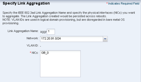
Define the following parameters in Specify Link Aggregation:
-
Link Aggregation Name – The name of the Link Aggregation is begins with aggr. Add a number to differentiate it from other aggregations.
-
Network – Select a network from the list.
-
NICs – List the physical interfaces of the selected network that must be configured as a single logical unit. Click Next to configure the link aggregation.
-
-
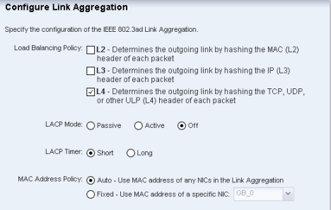
Configure the IEEE 802.3ad Link Aggregation with the following parameters in Configure Link Aggregation:
-
Load Balancing Policy – Define the polidy for outgoing traffic.
-
Aggregation Mode and Switches – If the aggregation topology involves connection through a switch, you must note if the switch supports the link aggregation control protocol (LACP). If the switch supports LACP, you must configure LACP for the switch and the aggregation. Define one of the modes in which LACP should operate.
-
MAC Address Policy – Define whether the MAC address of the NICs are fixed or not.
-
-
-
To use IPMP, enter the following information:
-
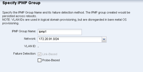
Define the following information in Specify IPMP Group:
-
IPMP Group Name – Provide a name for the IPMP group.
-
Network – Select a network from the list.
-
Failure Detection – The Link based detection is always embedded. If you want to include Probe based detection, select Probe based option. Click Next to specify the IPMP interfaces.
-
-
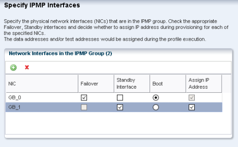
Define the following information in Specify IPMP Interfaces:
-
Specify the interfaces that will be part of the IPMP group.
-
Define the interfaces as Failover or Standby.
-
Configure additional IP addresses for the interfaces.
Note:
The data and test addresses are assigned during profile execution.Test address is not required for probe-based failure detection.
-
-
-
If you have selected none for networking option, select a DHCP enabled network interface for the boot interface in Select Networks.
-
Click the Add icon to add more than one network. Select a NIC from the list of available logical interfaces for each network. Select the Address Allocation Method for the selected networks except the boot interface. All the networks that are defined in Ops Center are displayed in the Network list. If you have selected Use Static IP for Address Allocation Method then you must provide the IP address when you apply the profile. The specific IP address is assigned to the target system after provisioning.
-
Click Next to view the Summary of the parameters selected for Oracle Solaris OS provisioning.
-
Review the parameters and click Finish to save the profile. The profile is created for provisioning Oracle Solaris OS.
Creating an OS Profile for Provisioning Linux OS
You can create OS profiles for provisioning on supported Linux OS on x86 systems. Whenever you import an OS image, a default profile is always created. You can either edit the profile or create a new profile.
-
Import the required OS image.
-
Verify that any scripts the profile uses are in a directory that the Ops Center Enterprise Controller can access. Scripts can be located in a local directory of the Enterprise Controller, or in a directory that the Enterprise Controller mounts using NFS.
To Create an OS Provisioning Profile for Linux OS
-
Click Plan Management in the Navigation pane.
-
Select OS Provisioning in the Profiles and Policies tree. A list of existing OS profiles is displayed in the center pane.
-
Click Create Profile in the Actions pane. The Create Profile-OS Provisioning wizard is displayed.
-
Define the profile parameters:
-
Name - Name of the profile.
-
Description - The description of the profile.
-
Create a deployment plan for this profile - This option is selected by default to automatically create a plan using this profile. However, you can deselect this option if you do not want to create a plan automatically.
-
Subtype - Select the Linux release, as per your requirement.
-
Target Type - The target types are automatically defined to x86.
-
-
Click Next to define the OSP Parameters.
-
Select an OS image in the OS Image List. The images that are applicable only for the selected subtype are listed.
-
Select a Distribution Type from the list of types. You can select more than one distribution.
-
Select Include Custom Scripts if you want to add any scripts. Specify the scripts if you want to include custom scripts.
-
Click the Add icon to add custom scripts.
-
Enter the script location, and specify whether you want to execute it before or after the provisioning operation. The scripts should be accessible from the Enterprise Controller.
-
-
Click Next to specify the OS setup.
-
Specify the following OS setup parameters:
-
Language - Select a language from the list.
-
TimeZone - Specify the time zone for the OS.
-
Terminal Type - Select a terminal type from the list.
-
Console Serial Port - To monitor the installation using a serial connection, select the correct console serial port device.
-
Console Baud Rate - To monitor the installation using a serial connection, select the correct serial port device baud rate.
-
Password - Enter the root password for the root user on systems provisioned using this profile. Re-enter the password for confirmation.
-
-
Select the Manual Net Boot option to enable manual control of network boot operations for the target system. You must select this option for a target system that does not have a service processor because Ops Center cannot remotely control the network boot process on these systems.
-
Select Automatically Manage with Oracle Enterprise Manager Ops Center to install the agent on the system and manage the system with Ops Center.
-
Click Next to specify the installation parameters.
-
For Oracle Linux, specify the following parameters:
Figure 8-5 Create OS Provisioning Profile
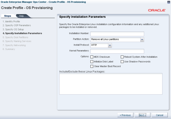
Description of "Figure 8-5 Create OS Provisioning Profile"
-
Installation number – You can enter the installation number that is used to allow installation of all of the Linux software that is included in your subscription.
-
Partition action – Select whether you want to change the disk partition of the system.
-
You can opt to remove all the existing Linux partitions and retain the non-Linux partitions. You can provide specification for the new partitions.
-
You can opt to preserve all the existing partitions. You must define new partitions, outside of the partitions that exist, in which to install the OS.
-
You can opt to remove all the existing partitions. Define specification for the new partitions.
-
-
Install protocol – Specify HTTP or NFS as the install protocol.
-
Kernel parameters – If necessary, enter kernel parameters for the GRUB menu of the target system.
-
MD5 Checksum – Select this option to use MD5 encryption for user passwords.
-
Reboot action – Select whether you want to reboot the target system after OS installation.
-
Disk label initialization – Select this option to initialize labels on new disks. This option creates labels that are appropriate for the target system architecture.
-
Shadow passwords – Select this option to use an /etc/shadow file to store passwords on the target system.
-
Clear master boot record – Select this option to clear all invalid partition tables.
-
Linux packages – You can specify the Linux packages that you want to include or exclude during provisioning. To include a package, enter the package name in a line. To exclude any package, enter the package name preceded by a dash ( - ).
-
-
For SUSE Linux, specify the following parameters:
-
FTP proxy server – Enter the name of the FTP proxy server to support FTP services.
-
HTTP proxy server – Enter the name of the HTTP proxy server to support HTTP services.
-
Install protocol – Specify HTTP or NFS as the install protocol.
-
Enable proxy servers – Select this option to enable the FTP and HTTP proxy servers that you specified in the FTP Proxy Server and HTTP Proxy Server fields.
-
Kernel parameters – Enter kernel parameters for the GRUB menu of the target system, if necessary.
-
Reboot action – Select whether you want to reboot the target system after OS installation.
-
Linux packages – You can specify the Linux packages that you want to include or exclude during provisioning. To include a package, enter the package name in a line. To exclude any package, enter the package name preceded by a dash ( - ).
-
-
Click Next to define the disk partitions.
-
Specify the disk partitions and file systems that you want to create on the target system.
-
Click the Add icon to define a new partition. The root (/) and a swap file system are defined by default. For each partition that you define, provide the following information:
-
File System Type – Select a file system type, either ufs, unnamed, or swap.
-
Mount Point – Enter a directory to use as a mount point for partitions.
-
Device – Enter the rootdisk keyword and a slice value to describe a partition on the target system's boot disk, for example, rootdisk.s0, or enter the logical device name, for example, c1t0d0s0, of the partition that you want to create.
-
Size (MB) – Enter the size that you want to assign to the partition, expressed in MB. When you want to allocate the remaining unused disk space to a file system, do not enter any value for the size.
-
-
Click Next to specify the naming services.
-
Specify the name service, domain name and the corresponding name server. You can select the following name service:
-
DNS – Enter the domain name of the DNS server. Provide the IP address of the DNS server in the Name Server field. You can enter up to three IP addresses as the value for the Name Server. Provide the additional domains to search for name service information in the Domain Name Search List. You can specify up to six domain names to search. The total length of each search entry cannot exceed 250 characters.
-
NIS or NIS+ – Enter the domain name of the NIS or NIS+ server. If you know the NIS server details, choose the option Specify an NIS Server and provide the NIS server host name and the IP address.
-
LDAP – Enter the domain name of the LDAP server. Specify the name of the LDAP Profile you want to use to configure the system. Enter the IP address of the LDAP Profile Server. You can also optionally provide the Proxy Bind Distinguished Name and Password.
-
None – Select None when there is no naming service configured.
-
-
Click Next to specify the networking.
-
Select the network interface that the target system will use after the OS has been installed. None is selected by default.
-
Click Next to select a DHCP enabled network interface for the boot interface.
-
Click the Add icon to add more than one network. Select a NIC from the list of available logical interfaces for each network. Select the Address Allocation Method for the selected networks except the boot interface. All the networks that are defined in Enterprise Manager Ops Center are displayed in the Network list. If you have selected Use Static IP for Address Allocation Method then you must provide the IP address when you apply the profile. The specific IP address is assigned to the target system after provisioning.
-
Click Next to view the summary of the parameters selected for Linux OS provisioning.
-
Review the parameters and click Finish to save the profile. The profile is created for provisioning Linux OS.
Creating an OS Profile for Provisioning Oracle VM Server
This section describes how to create an OS profile for Oracle VM Server. This profile is the first step towards installing the Oracle VM Server for SPARC software. In the profile, all the requirements for provisioning an Oracle VM Server such as parameters for installing an OS with the Oracle VM Server for SPARC software and resource definition for the Control Domain are all defined.
Use this profile to create a deployment plan and apply to provision the service processor with Oracle VM Server for SPARC.
Refer to Hardware and Provisioning Profiles and Deployment Plans for more information about creating profiles and plans, and applying the plans.
To Create an OS Profile for Oracle VM Server
-
Select Plan Management from the Navigation pane.
-
Select OS Provisioning option in the Profiles and Policies tree. The OS Provisioning page is displayed in the center pane.
-
Select Create Profile in the Actions pane. The Create Profile-OS Provisioning wizard is displayed.
-
In the Identify Profile step, provide the following information:
-
Enter a name for the profile.
-
Enter a description for the profile.
-
To create a deployment plan using this profile, select the option Create a deployment plan for this profile.
-
Select Oracle VM Server in the subtype to create a profile for installing Oracle VM Server for SPARC on the service processor.
-
-
Click Next to specify the OSP parameters.
-
Select an OS image in the OS Image List. Oracle Solaris 10 10/09 SPARC or higher versions will be populated in the image list for Oracle VM Server.
-
Select a Distribution Type from the list of types.
Note:
Minimum requirement of End User distribution is required. Distributions that are lower than End user will require additional package dependencies to be added. -
Select Include Custom Scripts if you want to add any scripts. You will directed to Specify Scripts if you have selected Include Custom Scripts.
-
Click the Add icon to add custom scripts.
-
Enter the script location, and specify if you want to execute it before or after the provisioning operation. The scripts must be accessible from Enterprise Controller.
-
-
Click Next to specify the OS setup.
-
Specify the following OS setup parameters:
-
Language – Select a Language from the list.
-
TimeZone – Specify the time zone for the OS.
-
Terminal Type – Select a terminal type from the list.
-
Console Serial Port – To monitor the installation using a serial connection, select the correct console serial port device.
-
Console Baud Rate – To monitor the installation using a serial connection, select the correct serial port device baud rate.
-
NFS4 Domain – Enter the NFS4 domain name that the target system will use. The dynamic value for NFSv4 domain name enables the NFSv4 domain to be derived dynamically, at run time, based on the naming service configuration. You can also provide valid domain name to hard code the value for NFSv4 domain.
-
Password – Enter the root password for the root user on systems provisioned using this profile. Re-enter the password for confirmation.
-
-
Select the Manual Net Boot option to enable manual control of network boot operations for the target system. You must select this option for a target system that does not have a service processor because Enterprise Manager Ops Center cannot remotely control the network boot process on these systems.
-
Select Automatically Manage with Oracle Enterprise Manager Ops Center to install an agent on the system and manage the system with Enterprise Manager Ops Center.
Note:
Ensure that for systems to be managed, you have selected the appropriate Distribution Type. Otherwise, the OS provisioning job can fail. -
Click Next to specify the JET modules and parameters.
-
Enter a comma-separated list of JET module names. Enter the names of any additional JET modules that you have installed on the Proxy Controller to perform the provisioning operations described by this profile. The base_config, custom, and flash JET modules are always installed, and you need not specify them here.
-
Click the Add icon to add JET name-value pairs. The JET parameters helps to customize how this profile provisions the target systems.
-
Enter the name of the JET parameter that you want to add in the Name field.
-
Enter the value that you want to assign to the JET parameter in the Value field.
-
Click Next to specify the Oracle VM Server Control Domain parameters,
-
Specify the following resources that you want to assign to the control domain:
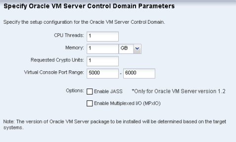
Description of the illustration ldom.png
-
CPU Threads – Specify the number of CPU threads that you want to assign to the control domain. The remaining CPU threads are available for the logical domains.
-
Memory – Specify the amount of memory that you want to assign to the control domain. The remaining memory is available for the logical domains.
-
Requested Crypto Units – Specify the number of crypto units that you want to assign to the control domain. The remaining crypto units are available for the logical domains.
-
Virtual Console Port Range – Specify the minimum port and maximum port of the virtual console of the control domain. The default port range for virtual console is 5000 to 6000.
-
Enable JASS – Select this check box to harden the system by installing the SUNWjass package.
Note:
JASS is not supported for Oracle VM Server for SPARC 1.3 or higher versions. This option is disregarded even if you select Enable JASS in the profile when Oracle VM Server for SPARC version 1.3 or 2.0 is being installed. -
Enable Multiplexed I/O (MPxIO) - Select this check box to enable Fibre Channel connectivity for the control domain. This action enables the Fibre Channel ports on the system that is configured for storage.
Note:
The version of Oracle VM Server for SPARC to be installed depends on the target systemsNote:
After the provisioning job starts, an information problem mentions the Oracle VM Server for SPARC version that is installed on the target server. -
-
Click Next to define the disk partitions.
-
Specify the disk partitions and file systems that you want to create on the target system.
-
Click the Add icon to define a new partition. The root (/) and a swap file system are defined by default. For each partition that you define, provide the following information:
-
File System Type – Select a file system type, either ufs, unnamed, or swap.
-
Mount Point – Enter a directory to use as a mount point for partitions.
-
Device – Enter the rootdisk keyword and a slice value to describe a partition on the target system's boot disk, for example, rootdisk.s0, or enter the logical device name, for example, c1t0d0s0, of the partition that you want to create.
-
Size (MB) – Enter the size that you want to assign to the partition, expressed in MB. Do not enter any value for the size when you want to allocate the remaining unused disk space to a file system.
-
-
Click Next to specify the naming services.
-
Specify the name service, domain name and the corresponding name server. You can select the following name service:
-
DNS – Enter the domain name of the DNS server. Provide the IP address of the DNS server in the Name Server field. You can enter up to three IP addresses as the value for the Name Server. Provide the additional domains to search for name service information in the Domain Name Search List. You can specify up to six domain names to search. The total length of each search entry cannot exceed 250 characters.
-
NIS or NIS+ – Enter the domain name of the NIS or NIS+ server. If you know the NIS server details, choose the option Specify an NIS Server and provide the NIS server host name and the IP address.
-
LDAP – Enter the domain name of the LDAP server. Specify the name of the LDAP Profile you want to use to configure the system. Enter the IP address of the LDAP Profile Server. You can also optionally provide the Proxy Bind Distinguished Name and Password.
-
None – Select None when there is no naming service configured.
-
-
Click Next to specify the networking.
-
Select the network interface that the target system will use after the OS has been installed. You can define the following options for networking:
-
Use Link Aggregation – Go to step 28
-
Use an IPMP group – Go to step 29
-
None – Go to step 27
-
-
Select a DHCP enabled network interface for the boot interface. Click the Add icon to add more than one network. Select a NIC from the list of available logical interfaces for each network. Select the Address Allocation Method for the selected networks except the boot interface. All the networks that are defined in Enterprise Manager Ops Center are displayed in the Network list. If you have selected Use Static IP for Address Allocation Method then you must provide the IP address when you apply the profile. The specific IP address is assigned to the target system after provisioning.
-
You must specify and configure the Link Aggregation.
-
In the Specify Link Aggregation step, enter the following details:
-
Link Aggregation Name – The name of the Link Aggregation is already set as aggr. Add a number to it to differentiate it from other aggregation.
-
Network – Select a network from the list.
-
NICs – List out the physical interfaces of the selected network that must be configured as a single logical unit. Click Next to configure the link aggregation.
-
-
In the Configure Link Aggregation step, configure the IEEE 802.3ad Link Aggregation with the following parameters:
-
Load Balancing Policy - Define the policy for outgoing traffic.
-
Aggregation Mode and Switches -- If the aggregation topology involves connection through a switch, you must note whether the switch supports the link aggregation control protocol (LACP). If the switch supports LACP, you must configure LACP for the switch and the aggregation. Define one of the modes in which LACP must operate.
-
MAC Address Policy - Define whether the MAC address of the NICs are fixed or not.
-
-
-
For IPMP group, you must specify the IPMP group and interfaces.
-
In the Specify IPMP Group step, define the following information:
-
IPMP Group Name - Provide a name for the IPMP group.
-
Network - Select a network from the list.
-
Failure Detection - The Link based detection is always embedded. If you want to include Probe based detection, select Probe based option. Click Next to specify the IPMP interfaces.
-
-
In the Specify IPMP Interfaces step, define the following information:
-
Specify the interfaces that will be part of the IPMP group.
-
Define the interfaces as Failover or Standby.
-
Configure additional IP addresses for the interfaces.
-
Note:
The data and test addresses will be assigned during profile execution.Note:
Test address is not required for probe-based failure detection. -
-
Click Next to view the Summary of the parameters selected for Oracle VM Server provisioning.
-
Review the parameters and click Finish to save the profile. The profile will be created for provisioning Oracle VM Server.
See Deployment Plans and Complex Plan Management for creating a plan with this profile and apply the plan to provision the Oracle VM Server.
Creating an OS Provisioning Profile with JET Templates
You can create OS provisioning profiles with JET templates. You can create your own JET templates and use it for Oracle Solaris OS provisioning. You can use the JET templates to standardize the configurations as it provides more options for defining the jumpstart parameters.
Ensure that you place the JET template on a directory that the Enterprise Controller can access. JET templates can be located in a local directory of the Enterprise Controller, or in a directory that the Enterprise Controller mounts using NFS.
You can also create a JET template on the Enterprise Controller in the directory /opt/SUNWjet/Templates, using the following command: ./make_template template_name
You can edit the template and fill in the OS information. Save the template.
You can change the values in the JET template as required. During provisioning the OS provisioning parameters are read from the template. Ensure that you have the template on the Enterprise Manager Ops Center before provisioning.
To Create an OS Provisioning Profile with JET Templates
-
In the Navigation pane, select Plan Management section.
-
Expand Profiles and Policies and select OS Provisioning profile. The existing OS provisioning profiles are listed in the center pane.
-
In the Actions pane, select Create Profile option. The Create Profile-OS Provisioning wizard is displayed.
-
Provide a name and description for the profile.
-
The Create a deployment plan for this profile option is selected by default. If you do not want to automatically create a plan, deselect the option.
-
In the Subtype list, select JET Template.
-
Select the Target Type as OSP x86 or OSP SPARC.
-
Click Next to define the OSP parameters.
-
Select an Oracle Solaris OS image from the available ISO images list.
-
Click Browse to select the JET template location on the Enterprise Controller.
-
Select the Manual Net Boot option to enable manual control of network boot operations for the target system. You must select this option for a target system that does not have a service processor because Enterprise Manager Ops Center cannot remotely control the network boot process on these systems.
-
Select Automatically Manage with Oracle Enterprise Manager Ops Center to install an Agent on the system and manage the system with Enterprise Manager Ops Center.
-
Click Next to specify the networks for the OS.
-
Click Next to select the network interface that the target system will use after the OS has been installed. You cannot define IPMP groups or link aggregation for a JET template profile.
-
Select a DHCP enabled network interface for the boot interface.
-
Click the Add icon to add more than one network. All the networks that are defined in Enterprise Manager Ops Center are displayed in the Network list.
-
Select a NIC from the list of available logical interfaces for each network. If you have selected Use Static IP for Address Allocation Method then you need to provide the IP address when you apply a deployment plan with this profile. The specific IP address is assigned to the target system after provisioning. You can select the Address Allocation Method for the selected networks except the boot interface.
-
Click Next to view the summary of the selected profile properties.
-
Click Finish to create the profile. On a successful job completion, an OS provisioning profile will be created. Create a plan from this profile and apply it on the server to provision the OS.
See Deployment Plans and Plans for information creating and applying a deployment plan associated with this profile.
For more information about JET Templates, see Additional Resources.
Logical Domain Profiles
Logical Domain profiles captures the requirements for creating a logical domain in an Oracle VM Server. Using the profile, you can create one or more logical domains. The logical domain provisioning is not covered in this profile. The logical domain profile specification require the domain identification, CPU Threads, memory, storage and networks information.
The OS provisioning profile provides option to provision the logical domains. These profiles have to be combined together in a plan and deployed for creating and provisioning logical domains.
You can create logical domains on an Oracle VM Server using the logical domain profiles. This plan involves only creating logical domains on the Oracle VM Server. You need to apply another plan of installing the OS on the created logical domains. Otherwise, see Configure and Install Logical Domains for complete steps of creating logical domains and installing OS on the domains.
Use this plan exclusively for creating only logical domains.
This section describes how to create a logical domain profile. Using this profile, you can create one or more logical domains on an Oracle VM Server. Use this profile in a plan combined with an OS provisioning profile for a complete logical domains installation.
Ensure that you have the following information before you create a profile:
-
CPU and memory requirements for the logical domains.
-
Storage resources.
-
Network resources and number of connections for a network.
To Create a Logical Domain Profile
-
Select the Plan section from the Navigation pane.
-
Select Logical Domain from the Profile tree.
-
Click Create Profile from the Actions pane. The Create Logical Domain Profile wizard is displayed.
-
Provide a name and description to identify the profile.
-
Select Create a deployment plan for this profile to automatically create a plan using this profile.
-
Click Next and provide a name and the starting number for the logical domain. Using this profile, you can create more than one logical domain. For unique identification of the domains to be created, provide a prefix start name and starting number. For example, assume that the Start Name is TestDomain and the starting number is 10. If the number of domain creation is 3, then the logical domains will be created with the name TestDomain10, TestDomain11 and TestDomain12.
-
Click Next to configure the CPU Threads and memory. The physical CPUs of the Oracle VM Server are shared among the CPU threads of all the logical domains. Each logical domain requires:
-
At least one Gigabyte of memory.
-
At least one CPU thread. Crypto units are assigned based on CPU thread assignments. You can request the number of crypto units to be assigned to the logical domain. However, the number of crypto units assigned might be different than the amount requested because we can only allocate a crypto unit for every given number of CPU thread allocation, depending on the server hardware.When the logical domain is created, view the job notification to see the actual number of Crypto Units assigned to the logical domain. You can edit the logical domain configuration, storage, and networks.
-
-
Click Next to specify the library for storing the domain metadata and storage disks for the logical domain.
-
Select a library to store the logical domain metadata. You can select only the local or NAS library to store the domain metadata.
-
Select one or more libraries that form the domain storage disks. The libraries for virtual disk can be local, local device, NAS, or Fibre Channel.
Note:
You can define the disk size for local and NAS libraries. Whereas, you cannot define the size for local device and Fibre Channel libraries. Select a disk from the list and the size of the disk is automatically displayed. -
Click Next to specify the networks for the domains.
-
Select at least one network from the list of networks identified by the Ops Center. You can associate a logical domain with more than one network.
-
Enter the number of connections for each network. You can connect to a network multiple times to the logical domain. When you create a logical domain, the number of connections for a network translate to the number of virtual network devices created for the logical domain. The number of virtual network devices created depends on the number of virtual switches present in the Control Domain. When you start a logical domain, you have to define the virtual switches through which you connect the logical domain to the external network.
-
Click Next to view the summary of the details selected for creating a logical domain.
-
Review the information and click Finish to save the profile. If you have opted to create a deployment plan with this profile in the first step, then a corresponding logical domain plan is also created.
Note:
If you make any changes to the profile, a new version of the profile is created. If required, you can change the profile reference in the plans that have used the older version of the profile.Cluster Profiles
You use cluster profiles in a deployment plan to perform the following operations:
-
Install Oracle Solaris Cluster software
-
Upgrade Oracle Solaris Cluster software
The profiles and deployment plans rely on pre-action and post-action scripts to suspend cluster operations and save configuration information during the update process.
The following cluster-specific profiles and scripts are located in Enterprise Manager Ops Center's Local Content software library. As the Oracle Solaris Cluster software is revised, new profiles are made available to you through the Java.net site's Ops Center Cluster Profiles project. You download these new profiles and scripts, then import them into the Local Content library. See Obtaining the Cluster Profiles and Scripts for instructions to get these files.
-
Profiles for Provisioning Oracle Solaris Cluster Software version 3.2u3
-
SPARC
-
sc-3.2u3-core-sparc
-
sc-3.2u3-manager-sparc
-
sc-3.2u3-agents-sparc
-
-
x86
-
sc-3.2u3-core-x86
-
sc-3.2u3-manager-x86
-
sc-3.2u3-agents-x86
-
-
-
Profiles for Upgrading Version 3.2u3 to Version 3.3 or for Provisioning an Oracle Solaris Cluster Software Version 3.3
-
SPARC
-
sc-3.3-core-sparc
-
sc-3.3-manager-sparc
-
sc-3.3-agents-sparc
-
-
x86
-
sc-3.3-core-x86
-
sc-3.3-manager-x86
-
sc-3.3-agents-x86
-
-
-
Scripts for pre-action and post-action
-
Post-action script for provisioning either version 3.2 or 3.3: SolarisCluster-Post.ksh
-
Post-action script for upgrading version 3.2 to 3.3: SolarisCluster3.21109-Post
-
Pre-action script for upgrading version 3.2 to 3.3: SolarisCluster3.21109-Pre
-
Obtaining the Cluster Profiles and Scripts
To obtain profiles and scripts for a new release of Oracle Solaris s Cluster software, download them to the system that is running the Enterprise Controller.
Note:
When you download, transfer, upload, or import these files, do not change the file name. Keep the same name throughout the procedure.To Obtain the Cluster Profiles and Scripts
-
Click the Downloads button.
-
Select the folder for the profiles you want:
-
To provision Oracle Solaris Cluster Software version 3.2u3, select the Version-3.2u3 folder.
-
To upgrade version 3.2u3 to version 3.3, select the Version-3.3 folder.
-
To provision Oracle Solaris Cluster Software version 3.3, select the Version-3.3 folder.
-
-
In the version folder, select the platform you want, either SPARC or x86.
The platform folder contains three files: Agents, Core, and Manager. You need all three files to complete upgrade or provision operations.
-
Use the browser window's Save feature to save each file, keeping its file name.
-
Return to the home page for the project and select the Action-Scripts folder.
-
Select the scripts that complete the core profiles:
-
To upgrade version 3.2u3 to version 3.3, select the Pre-Upgrade and Post-Upgrade scripts.
-
To provision version 3.2u3 or version 3.3, select the Post-Provision script.
-
-
Upload the profiles and scripts, according to Uploading the Cluster Profiles and Scripts.
Uploading the Cluster Profiles and Scripts
The files containing the profiles and scripts must reside on the same system that is running the browser and they must reside in the same directory. This operation uploads all files in the selected directory.
-
Move the profiles and scripts to the appropriate system and directory.
-
Expand Libraries in the Navigation pane.
-
Click Local Content in the Solaris/Linux OS Updates library.
-
Click Bulk Upload Packages and Patches in the Actions pane.
-
Click Distribution to select the distribution that applies to these files.
-
Select Upload from Directory.
-
Specify the path to the directory or click Browse to locate and select it.
All files in the directory and its subdirectories are uploaded.
-
Click Submit.
-
Import the profiles into Enterprise Manager Ops Center, according to Importing Cluster Profiles and Scripts.
Importing Cluster Profiles and Scripts
-
To import profiles, use the browser on the same system or transfer the profiles to the system on which you are running the browser.
-
To import scripts, transfer the files to the Enterprise Controller's system.
Note:
When you download, transfer, upload, or import these files, do not change the file name. Keep the same name throughout the procedure.
-
Expand Plan Management in the Navigation pane.
-
Click Update Profiles.
-
Click the Import Profile icon.
-
For each profile and script:
-
Enter the name of the file you downloaded. Do not change the name.
-
Click Import.
-
-
Expand Libraries in the Navigation pane.
-
Select Solaris/Linux OS Updates.
-
Select Local Content.
-
Click Upload Local Action.
-
For each profile:
-
Enter the name of the profile as you want it to be displayed in the Plan Management section.
-
Select the distribution of the OS that uses the profile.
-
Enter the name of the file that contains the profile. Do not change the name.
-
Click Upload.
-
-
For each script:
-
Select action type, the matching parent category, and the OS distribution.
-
Enter the name of the file that contains the script. Do not change the name.
-
Click Upload.
-
-
For provisioning profiles, edit the core profiles to include the Post-Provision scripts, according to Editing the Core Profile for Provisioning
To upgrade a cluster, no modification is needed because the scripts are available to the upgrade profile after the import operation.
Editing the Core Profile for Provisioning
-
Expand Plan Management in the Navigation pane.
-
Click Update Profiles.
-
In the OS Update Profiles table, select the core profile.
-
Click the Edit Profile icon.
-
In the Edit OS Update Profile window, navigate from Local to either Post-actions or Pre-action.
-
Select the script and click Required. For example, to edit the core profile for provisioning, navigate to Post-actions, select SolarisCluster-Post.ksh, and click Required. The file is now listed in the Profile Contents section.
-
Click the Saved as Named Profile button.
Managing Profiles
All functions such as configuring service processors, provisioning servers, and updating in Ops Center can be captured in the form of profiles and used again and again to create consistent configurations.
Profiles form the building blocks upon which the deployment plans are created. You need to manage the profiles, and its versions. Name your profiles for clear understanding. Depending on the user role prescribed, you have options to view, edit, copy, delete profiles.
Viewing Profiles
You can select a profile and view its details, plans that use the profile, and the version history of the profile.
-
Select Plan Management section from the Navigation pane.
-
Select a profile type from the Profiles and Policies tree.
-
Choose a profile from the list of profiles. The profile details of the latest version are displayed in the center pane:
-
Name and description of the profile
-
Subtype - The different types of product for which you want to create a profile
-
Target type - Defines the type of hardware on which the profile can be applied
-
Version and last modified date
-
The parameters that are collected for creating a profile are displayed.
-
-
Select Referrers tab in the center pane. The plans that reference the selected profile are listed.
-
Select Version History tab in the center pane. The versions that are available for the profile are listed.
-
Select a version and click the View Version Details icon. The profile details are displayed.
The profile with different versions will be displayed with the version number while selecting them in a plan. For example, if the profile name is logdom, the versions of it will be displayed as logdom v1 and logdom v2.
Copying Profiles
You can create an exact instance of an existing profile using the Copy Profile option. You create another profile with a new name for the profile. You can edit the other parameters of the profile except for the target type and sub type of the profile.
-
Select Plan Management section from the Navigation pane.
-
Select the profile type from the Profiles and Policies tree.
-
Select a profile from the list. The profile details are displayed in the center pane.
-
Select Copy Profile from the Actions pane. Alternatively, you can select the profile type, select the profile from the list in the center pane and click the Copy Profile icon. The corresponding Create Profile wizard is displayed.
-
Edit the parameters in the wizard as required. The name of the profile is displayed as Copy of <profile name>. You can modify the name and other parameters of the profile as required. You cannot modify the profile parameters Subtype and Target type of the profile.
-
Click Finish to copy the profile. The profile will be copied and the new profile will be listed.
Editing Profiles
You can edit the profile parameters in Ops Center. When you edit the profile parameters, a new version of the profile will be created. If you change the name of the profile, then it will be created as a new profile and the existing profile will not be modified.
Note:
When you edit a profile, the plans that refer to the profile are not updated to the new profile version. You need to update the plan to the updated profile version, as required.You must have appropriate roles and permissions to edit the profiles.
-
Select Plan Management from the Navigation pane.
-
Select the profile type from the Profiles and Policies tree.
-
Select a profile from the list that you want to modify. The selected profile details are displayed in the center pane.
-
Select Edit Profile in the Actions pane. Alternatively, you can select the profile type, select the profile from the list in the center pane and click the Edit Profile icon. The Edit Profile wizard displays.
-
Modify the profile parameters as required in the wizard.
Note:
If you change the name, the profile is stored as a new profile. -
Click Finish to update the profile. The profile is saved with the new changes and the version is incremented by 1.
Deleting Profiles
You can delete the profile versions that you have created.
To Delete a Version of a Profile
-
Select Plan Management from the Navigation pane.
-
Select the profile type from the Profiles and Policies tree.
-
Select the profile that you want to delete. The profile details are displayed in the center pane.
-
Select Delete Version in the Actions pane to delete the latest version.
-
To delete previous versions, select Version History in the center pane. All the versions of the profile are listed.
-
Select a profile version.
-
Click the Delete Version icon.
-
Confirm the delete action.
The selected version of the profile will be deleted and any plans that references the profile will be updated accordingly. You need to update the plans manually that references the deleted profile.