Rule Basics
This chapter covers the following topics:
- Introduction to Configuration Rules
- Types of Configuration Rules
- Imported BOM Rules
- Using Node Properties when Defining Configuration Rules
- Configuration Rules and Logic State
- Rules that Relate Components and Models
- Unsatisfied Rules
Introduction to Configuration Rules
One of the most critical activities in constructing a configuration model is to design and construct the rules that govern what the end user can select to make a valid configuration. You need to define rules that express relations and compatibilities among the Components, Features, Options, BOM Option Classes, and BOM Standard Items in your Model. Configuration rules are essential in ensuring that a configured product can be ordered and manufactured successfully.
In a configuration model, rules identify Model elements that are:
-
Used as general defaults
-
Automatically selected when an end user selects another option
-
Permitted when an end user selects another option
-
Excluded when an end user selects another option
For suggestions about defining rules for best runtime performance, refer to the following documentation:
-
Oracle Configurator Modeling Guide
-
Oracle Configurator Performance Guide
Types of Configuration Rules
Configuration Rule Types summarizes each type of rule.
| Rule Type | Description |
|---|---|
| Logic (see Logical Relationships) | Defines a logical relationship between most types of Features, Options, and any type of BOM nodes. |
| Numeric (see Introduction to Numeric Rules ) | Express constraints between Model objects in terms of numeric relationships. |
| Comparison (see ( Introduction to Comparison Rules ) | Performs a comparison between the values or Properties of two nodes, or a constant value. |
| Property-based Compatibility (see Introduction to Compatibility Rules ) | Specifies matches between the options of one or more Features or BOM Option Classes that have a common Property. |
| Explicit Compatibility (see Introduction to Compatibility Rules ) | Specifies matches between the options of one or more Features or BOM Option Classes in explicit tabular form. |
| Design Chart (see Introduction to Design Charts ) | Specifies compatibility matches among the options of Features or BOM Option Classes in explicit tabular form. |
| Statement (see Overview of Statement Rules ) | Allows more complex expressions and constraint definitions using the Constraint Definition Language (CDL). |
| Rule Sequences (see Introduction to Rule Sequences ) | Specifies an ordered set of rules whose effectivity dates are set so that a rule in the sequence becomes effective at the same time its predecessor ceases to be effective. |
| Configurator Extensions (see Introduction to Configurator Extensions | Use Java code that you write to perform functions that go beyond the functionality and rules that Oracle Configurator Developer provides. |
Creating Rules
You create all types of rules (except Java code for a Configurator Extension Rule) in the Rules area of the Workbench. The steps to create a rule vary depending on the rule’s type. For details, see Introduction to the Rules Area of the Workbench.
Rule Folders
In the Rules area of the Workbench, each Model contains a default Configuration Rules Folder. Within this Folder, you can create as many sub-Folders as you need to organize a Model’s rules.
Rule Folders that you create can contain any type of rule. You can copy rules and move them from one Folder to another. However, the same rule cannot reside in more than one Folder. Copying a rule to a different Folder creates a new, separate rule that can be modified independently of the original.
To create a rule Folder, see Creating a Rule Folder.
Rule Sequences
A Rule Sequence is a set of rules that are active according to their order in the sequence, which is determined by each rule’s effectivity dates. For details, seeIntroduction to Rule Sequences.
Enabling and Disabling Rules
Enabling and disabling rules can be a useful tool when unit testing and debugging a configuration model. Rules that are disabled are ignored when you generate logic and when you unit test a Model in a runtime Oracle Configurator or the Model Debugger. You can enable or disable any type of rule.
The Disabled column in the Rules area of the Workbench shows whether a rule is currently active. When you enable or disable a rule, Configurator Developer updates this column only after you regenerate logic.
To enable or disable a rule, see Enabling and Disabling Rules.
Imported BOM Rules
Basic rules that are inherent in a BOM Model are imported and automatically applied in Oracle Configurator Developer. These rules include settings that indicate whether components in the BOM are optional or mutually exclusive, as well as any Quantity Cascade calculations. For example:
-
Required rules apply to child nodes that become required in the configuration when their parent node is selected. The name of this setting in Configurator Developer is "Required when Parent is Selected." For example, if this setting is Yes for Option Class X, Oracle Configurator automatically selects it when the end user selects its parent BOM Model.
-
Mutually Exclusive rules apply to nodes that allow only one of their optional child nodes to be selected at a time. The name of this setting in Configurator Developer is "Optional Children are Mutually Exclusive." For example, if the options within a BOM Option Class are mutually exclusive, an Oracle Configurator end user can select only one of them. This is similar to an Option Feature with a Maximum Selections of 1.
In Oracle Bills of Material, BOM Models that are children (components) of a BOM can be mutually exclusive. However, when you import such a BOM Model, Configurator Developer sets the Mutually Exclusive setting to No for each child (referenced) BOM Model. This is not an issue for most installations, and you can define rules that require a BOM Model’s children to be mutually exclusive, if necessary.
Quantity Cascade calculations are explained in Quantity Cascade Calculations.
In Configurator Developer, you can view how these rules are defined by viewing a BOM node’s definition in the Structure area of the Workbench. See Definition.
All of an optional BOM Model’s required children have an initial logic state of Unknown. Any required child items under the root BOM Model have an initial logic state of true, due to the inherent BOM rules described in the preceding paragraphs. Note that the root BOM Model cannot be optional, and any BOM item that is required has the "Required when parent is selected" setting set to Yes. This setting is described in Definition.
For more information about initial logic states, see Initial Logic State.
Quantity Cascade Calculations
Quantity Cascade calculations determine the final quantity requirements for a selected BOM item’s children.
When you import a BOM Model, all of the parent-to-child relationships that exist among the components in the BOM are maintained. A parent component (such as a BOM Option Class) may have multiple children; some required, some optional, and some mutually exclusive. When a parent is selected in a runtime Oracle Configurator, all of its required children are also selected. Similarly, when any child is selected, its parent is also selected.
Each component in a BOM is imported with a Minimum Quantity, Maximum Quantity, and Default Quantity. The Minimum Quantity is the smallest number of the selected node allowed per parent. The Maximum Quantity is the largest number of the selected node allowed per parent. The Default Quantity is how many of the selected node will be ordered (per parent) if this value is not modified in the selection process.
Whenever the number of a selected option is greater than zero, a Quantity Cascade calculation is performed which results in the actual quantity (or count) for that BOM item. The Quantity Cascade calculation is:
child node actual quantity = (parent node actual quantity) X (child node default quantity)
This calculation is true when the end user selects the parent item (for example, a BOM Option Class) and one of its children (a BOM Standard Item), but does not change the amount of the child item. Therefore, the count of the child is derived from the equation shown above.
However, if the end user enters a different amount for the child (BOM Standard Item) and then changes the amount of the parent (BOM Option Class), the Quantity Cascade calculation is:
( new child node amount / current child node amount ) X (old parent node amount) = new parent node amount
For example, Option Class A (the parent node) contains Option1 (the child node). Option1 has an initial count of 2. The end user sets Option1 to 4 and then changes Option Class A to 3. The Quantity Cascade calculation determines a new amount for Option1 as follows:
( 4 / 2 ) X 3 = 6
Note that the calculation ensures that the new amount of the child node (6) is a multiple of its default quantity (2).
These Quantity Cascade relationships reflect the relationships between components that are built into the BOM to ensure that it is complete and valid before ordering.
Quantity Cascade Calculation
A BOM Model for an automobile specifies four wheels and five lug nuts for each wheel. If you select the car, that means you must have four wheels and 20 lug nuts. Similarly, if you select one wheel, that forces selection of the car, which forces the Quantity Cascade calculation; therefore, four wheels and a total of 20 lug nuts are ordered. The Numeric Rules you define in Configurator Developer respect these Quantity Cascade relationships.
All quantities for BOM Standard Items are calculated this way and are propagated from the root node down through the entire BOM Model. For more information, see Contributing to BOM Item Quantities.
Initialization Behavior
There are some special considerations for handling BOM quantity values. See the Oracle Configurator Implementation Guide for a description of the model_quantity initialization parameter.
Using Node Properties when Defining Configuration Rules
When defining a rule, you select Model nodes that will participate in the rule. A participating node’s User Property or System Property can also be part of a rule’s definition. For example, you may want selection of an option to decrease the value of Resource X, or increase how many instances of Component A are allowed in the configuration.
When defining a Logic, Numeric, or Comparison Rule, after you select the Model node(s) that participate in the rule, click Choose Properties instead of Apply. Then, select a Property from the list for each rule participant.
User and System Properties are explained in Introduction to Properties.
For more information about using Properties when defining rules, see:
Using Multiple Node Properties in a Rule
There may be times when you need to define a Logic, Numeric, or Comparison Rule, and use more than one of a node’s Properties. To do this, you must convert the rule to, or define it from scratch as, a Statement Rule. For example:Each option within Option Class Y has a User Property called Memory Supplied. When one of these options is selected at runtime, you want to contribute the value of the Memory Supplied User Property to a Total. You cannot do this simply by defining a Numeric Rule like the one described previously and specifying the Memory Supplied Property. This is because the rule’s definition requires both the Selection System Property and the Memory Supplied User Property to contribute the value of Memory Supplied to the Total.
To create this expression, you must define the following Statement Rule:
Contribute ‘Option Class Y'.Selection().Property(“Memory Supplied") TO ‘Total Memory Supplied'.Value()
For more information about Statement Rules, see Overview of Statement Rules .
Configuration Rules and Logic State
To enforce the rules you define in Configurator Developer, the runtime Oracle Configurator maintains a logic state for all selectable options. A selectable option is any part of a Model that can be added to a configuration. Options can be selected by an Oracle Configurator end user, by either explicitly selecting something or entering a value in an input field, or by the propagation of a rule.
Model nodes that are selectable in a configuration model, and therefore have a logic state, include all types of Features, Feature Options, optional BOM Models, BOM Option Classes, and BOM Standard Items.
In general, an option’s logic state can be:
-
True: The option is included in the configuration.
-
False: The option is not included in the configuration.
-
Unknown: This means that no decision has been made about the option, and it is neither included in nor excluded from the configuration.
For example, an option is not selected when the configuration session begins or an Integer Feature whose initial value is 0 (zero).
Oracle Configurator and Configurator Developer also use variations of the True and False logic states to identify how an option is included or excluded from a configuration. This is because an option can be added to a configuration or excluded from a configuration either by explicit end-user action (for example, selecting an option), or as a consequence of a configuration rule.
When an end user selects an option, its logic state becomes User True. When the propagation of a rule causes an option to be selected, its logic state becomes Logic True. For example, a Logic Rule states "Option A Implies Option B." When the end user selects Option A, Oracle Configurator selects Option B. Therefore, Option A’s logic state is User True while Option B’s logic state is Logic True.
When an end user deselects an option that was selected by a rule, the option’s logic state is set to User False. Deselecting an option that the end user previously selected sets the option’s logic state to Unknown. When an option is excluded by the action of one or more configuration rules, its logic state is set to Logic False (see Things to Consider).
An option’s logic state is related to its selection state at runtime. The runtime Oracle Configurator uses this information to determine how to display options and status indicator images in a generated User Interface. For details, see:
Things to Consider
There may be times when an option has a logic state of Logic False but it is still available for selection. This can occur, for example, because of a Defaults Logic Rule or a Maximum Selections relation where the maximum is greater than one. In this case, an option has a logic state of Logic False but the icon used to display the item in the runtime UI make it appear as though its logic state is Unknown (the corresponding selection state is Not Selected). By default, Oracle Configurator does not use the Auto-Excluded icon with such options so your end users do not mistakenly believe that they are unavailable for selection or that selecting them will cause a contradiction message.
A BOM Option Class or Option Feature can be either satisfied or unsatisfied at runtime. These nodes are unsatisfied when they are selected (logic state is either Logic True or User True) but none of their children are selected. In other words, the BOM Option Class or Option Feature still requires input or contains at least one required selection.
To see the default icons that are used to indicate logic state at runtime, refer to Default Selection State and Status Indicator Images.
Generating Logic
At runtime, the Model structure, Model logic, and the runtime UI determine what is available for selection and how information is displayed. Before unit testing or publishing a configuration model, generate Model logic to be sure that it is up-to-date.
Generating logic:
-
Loads the Model structure and rules data from the database
-
Checks for incomplete rules and inconsistent logic
-
Converts the structure and rules data into a format that is usable by the runtime Logic Engine
You generate logic in the General area of the Workbench. For more information, see Logic Generation Status.
Initial Logic State
When a configuration session begins, all options have an initial logic state of Unknown, with the following exceptions:
-
Features that have an initial value defined may be either Logic True or Logic False.
See Initial Values.
-
Logic Rules that use the Defaults relation can cause options to be selected (Logic True) or excluded (Logic False).
See Defaults.
-
Option Features that have a Minimum Selections set to 1 or greater have an initial logic state of Logic True. This is because at least one of the Feature’s Options must be selected to create a valid configuration (in other words, it is required).
-
Features that have an initial value defined in Configurator Developer have an initial logic state of Logic True.
Indicating Logic State in the Runtime User Interface
At runtime, Oracle Configurator keeps track of each option’s logic state and determines what is displayed to the end user using the following:
-
The option’s selection state.
For details, see Selection State.
-
The images that your UI Master Template uses to indicate selection state and display Enhanced Check Boxes and Enhanced Radio Buttons and at runtime.
For details, see Images Section.
Effectivity and Logic State
Because you can enter an effective date or assign Usages to Model structure nodes in Configurator Developer, there may be times when one or more participants in a rule are not available at runtime. When a node is not available at runtime because of its effectivity, it does not appear in the runtime UI, it is considered by the configuration session to have a logic state of Logic False, and any rules in which the node is a participant behave accordingly.
Consider the Model shown in Effectivity and Logic State.
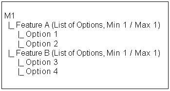
You assign an effective date to Feature A and create the following Logic Rule:
Option 1 Requires Option 3
At runtime, the date passed to the configuration session does not match the effective date range assigned to Feature A in Configurator Developer. Therefore, Feature A and its Options do not exist in the configuration, and Option 1 and Option 2 are set to Logic False when the configuration session begins. Option 1 is part of the Logic Rule mentioned above, so Option 3 is also set to Logic False. See The Requires Relation.
Effectivity is discussed in Introduction to Effectivity.
Enforcing Logical Relationships
The rules you create in Oracle Configurator Developer shape the choices an end user can make in the runtime Oracle Configurator. If the end user makes a selection that violates a rule, Oracle Configurator displays a message that describes how the selection affects the configuration as a whole. When a rule is violated, part of the message that appears at runtime is derived from the message you define when creating the rule. For details see Violation Message.
For example, an Oracle Configurator end user sets a Numeric Feature to a value that exceeds its defined maximum. Oracle Configurator displays a message similar to the one shown in Maximum Exceeded Message.
The current value of Inner Diameter is 15. This is above its maximum of 5.
In this case, the end user must enter a new value that is within the defined range for the Feature to continue.
However, Numeric Rules are handled differently. If the user selects values that cause a Numeric Feature to exceed its defined maximum or minimum values, the value of a Total is exceeded, or a Resource is overconsumed, Oracle Configurator displays a message similar to the one shown in Invalid Configuration Message.
Invalid Items: The current value of Inner Diameter is 15. This is above its maximum of 5.
Choose OK to proceed or choose Cancel to return to making your selections.
If the end user attempts to save the configuration in this state, or any other state that violates the rules you have established, Oracle Configurator displays a message similar to the one shown in Unsatisfied Configuration Message.
Unsatisfied Configuration Message
Unsatisfied Items: Component BR-90, Test Model M1. Your model is not complete. There are items that need to be selected or adjusted. If you continue, the incomplete model will be saved.
Choose OK to proceed or choose Cancel to return to making your selections.
The end user can save the incomplete configuration by clicking OK.
If the end user attempts to make a change to the configuration that violates one or more other rules, Oracle Configurator displays a contradiction message similar to the one shown in Contradiction Message.
There is a contradiction selecting Option A:
You cannot select both Option A and Option C.
If you make this change it will have the following consequences:
Option C will be deselected.
Do you want to make this change?
The end user must either agree to reject the last selection or indicate that the change should be made. In the latter case, the system changes values of other Features, Options, and so on until the configuration is restored to a valid state. (In this example, "You cannot select both Option A and Option C" is the custom violation message defined for the rule that was violated. For details, see Violation Message.)
If an end user’s selection triggers a rule that causes an option to become Logic False, it appears as System Excluded in the runtime UI (for details, see Indicating Logic State in the Runtime User Interface.) If an end user then selects the option, Oracle Configurator displays a contradiction message, and the end user must click OK or Cancel before proceeding.
Option Features with a Maximum Selections of 1 and BOM Option Classes that have mutually exclusive children that are User False have a Selection State of Selectable. An end user can select such options without receiving a contradiction message. Selection State is explained in Selection State.
You can also define conditions for displaying options at runtime. For more information, see Defining a Condition for Runtime Display and Behavior.
Unknown Values and Rule Propagation
When the end user starts a new configuration in a deployed Oracle Configurator, many elements in the Model structure have a logic state of Unknown until the user makes a selection. In general, Unknown values within the First Operand side of a rule do not cause the rule to propagate.
If a rule contains multiple participant, and the expression specified involves either the minimum or maximum number of component instances or the operators ’+’ or ’-’, the rule propagates when the end user makes a selection. In other words, when a participant within the expression is no longer Unknown.
For example, you create the following Statement Rule:
CONTRIBUTE (A + B) TO D
If both A and B are Unknown, the rule does not propagate. If A, B, or both options are selected, the rule propagates and contributes a value to D.
If the expression in a rule involves the operators ’*’ or ’/’, the rule propagates if one rule participant within the expression is not Unknown and has a value of 0, or if all participants within the expression are not Unknown.
Numeric Rules involving Property values do not propagate unless the option with the Property is selected.
When any node that can have a logic state is a participant in a rule and the value of the option is 0 at runtime, its logic state is Unknown and the rule does not propagate until its value changes. For example, you define the following rule:
Option1 = 0 NEGATES Feature2
This rule does not propagate when Option1 is set to zero, regardless of whether it is set to zero by default (that is, it has a value of 0 when the configuration session begins) or it is set to zero by the end user.
To learn which nodes can have a logic state at runtime, see Configuration Rules and Logic State.
Overriding User Selections without Notification
At runtime, there may be times when the runtime Oracle Configurator deselects one of an end user’s previous selections but does not display a message to alert the end user of the change.
Oracle Configurator automatically deselects an option in the runtime UI when both of the following are true:
-
An end user selects an option that causes the maximum selections of its parent Feature or BOM Option Class to be exceeded
-
Any one of the previous selections was made by the end user (that is, its logic state is User True)
However, Oracle Configurator cannot deselect an option that is a child of a Feature or BOM Option Class if the option was selected by the action of a rule (that is, its logic state is Logic True). If none of the previous selections were made by the end user, no override occurs and Oracle Configurator displays a violation message.
For example, an Option Feature called f1 has a minimum of 1 and a maximum of 2. This Feature contains 3 Options: o1, o2, and o3. The maximum of f1 is reached (2 options are selected) either by end user selection or by the action of a rule. The third option’s logic state is Unknown and it is therefore available. When the end user selects the third option, Oracle Configurator may override a previous selection, depending on how the selections were made.
Consider these examples:
-
If o1 and o2 are User True and o3 is selected, Oracle Configurator deselects the most recent end user selection and selects o3.
-
If o1 is User True and o2 is Logic True and the user selects o3, Oracle Configurator deselects o1.
-
If o2 is being contributed to from another item, both o1 and o2 are User True, and the user selects o3, Oracle Configurator deselects o1.
-
If both o1 and o2 are Logic True and the user selects o3, there is a contradiction and o3 cannot be made true. In this case, Oracle Configurator displays a violation message.
For more information on logic states, see Configuration Rules and Logic State.
Rules that Relate Components and Models
Before reading this section, you should be familiar with the concepts and terms presented in Introduction to Instantiation .
There are some restrictions you must keep in mind when constructing rules that relate Components and Referenced Models (this section refers to these nodes collectively as "components"). A rule relates two components if one or more nodes from each component’s structure are participants in the rule.
To understand the restrictions that exist when relating optional components, you must understand the following terms that have specific meaning within Oracle Configurator Developer:
-
A required component is a component whose Instantiability setting is Required Single Instance.
-
An optional instantiable component is a component whose Instantiability setting is Optional Single Instance.
-
An instantiable component is a component whose Instantiability setting is Multiple or Variable Instances.
For details about these settings, see Instances.
-
The required substructure of a component consists of the component itself, all of its required children, all of their required children and so on down to, but not including, any instantiable components.
-
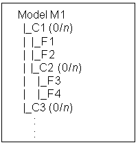
Components are independently instantiable multiple times when the existence of one instantiable component at runtime does not require the existence of the other. In other words, the components are instantiable and exist at the same level in the Model structure (that is, they do not have a parent-child relationship).
A rule cannot relate two or more components that are independently instantiable multiple times. In Component that is Independently Instantiable Multiple Times , C1 and C3 are independently instantiable multiple times, but C1 and C2 are not (because C2 is a child of C1).
Component that is Independently Instantiable Multiple Times
Examples of Valid Rules
Following are some examples of valid rules that relate runtime components.
Rule Relating Components within Required Substructure
A rule is valid if it relates components within a component’s required substructure.
Consider the Model structure shown in Components within Required Substructure.
Components within Required Substructure
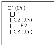
In this Model, "F1 Requires F2" is a valid Logic Rule.
Rule Relating Components within Parent’s Required Substructure
A rule is valid if it relates components within the required substructure of any parent component. In other words, you can create a rule involving any number and any level of components as long as all of them are within the required substructure of a single parent component.
Rule Relating Components that are Instantiable Multiple Times
Consider the structure shown in Components within Parent Component’s Substructure. In this Model, C1, C2, and C3 are all Components. C1 is the parent of both C2 and C3. You can create a rule that relates components C1 and C2, or C1 and C3, because any instance of C2 has direct visibility with its only parent (C1) and any instance of C3 has direct visibility with its only parent (C1).
You can create a rule that relates components C2 and C3 only when the Minimum and Maximum instances is 0/1 for both C2 and C3. You cannot create a rule that relates C2 and C3 when their Maximum instances is greater than 1; this is because they exist at the same level in the Model structure.
Components within Parent Component’s Substructure

In this Model, "F1 Requires F2" is a valid Logic Rule.
Additionally, you can create a valid rule between C2 and C3 if:
-
Both C2 and C3 are required (Initial Minimum = 1 or more).
-
Both C2 and C3 are optional (Initial Minimum = 0).
-
Either C2 or C3 is required, and the other is either optional or instantiable multiple times.
However, you cannot create a rule between C2 and C3 if:
-
Both C2 and C3 are instantiable multiple times (for an example, see Rule Relating Sibling Components that are Instantiable Multiple Times).
-
Either C2 or C3 is optional, and the other is instantiable multiple times.
Rule Relating an Optional Component with Sibling Optional Components
A rule is valid if it relates an optional component with any number of sibling optional components.
Consider the structure shown in Optional Component and Sibling Optional Components.
Optional Component and Sibling Optional Components
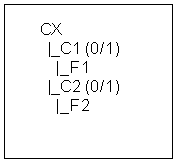
In this Model, "F1 Requires F2" is a valid Logic Rule.
Rule Relating Connected Components
A rule is valid if it relates any two components and a Connector connects one component to the other.
Consider the structure shown in Component with a Connector.
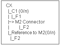
The Logic Rule "F1 Requires F2" is valid if you select F2 from the structure of the Connector’s target Model (M2) when defining the rule. The rule is not valid if you select the node from the referenced Model’s structure when defining the rule.
For more information about defining rules using structure of a target Model, see Connectors and Target Models.
Examples of Invalid Rules
Following are some examples of invalid rule definitions.
Rule Relating Sibling Components that are Instantiable Multiple Times
A rule is not valid if it relates two Components that are instantiable multiple times and exist at the same level in the Model structure.
Consider the structure shown in Sibling Components that are Instantiable Multiple Times.
The graphic Sibling Components that are Instantiable Multiple Times shows a hierarchical Model structure for Component CX, which contains two Components, C1 and C2, both of which have a min/max of 0/n. Component C1 has one Feature called F1, and C2 has one Feature called F2.
Sibling Components that are Instantiable Multiple Times

A Logic Rule whose definition is "F1 Requires F2" is invalid.
Rule Relating Components within Required, Instantiable Substructure
A rule is invalid if it relates a component that is instantiable multiple times with a component in the required substructure of another component that is also instantiable multiple times and exists at the same level in the Model.
Consider the structure shown in Sibling Instantiable Components with Required Substructure.
Sibling Instantiable Components with Required Substructure
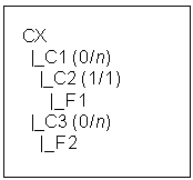
A Logic Rule whose definition is "F1 Requires F2" is invalid.
Rule Relating Optional Component with Instantiable Component
A rule is invalid if it relates an optional component with one other component that is instantiable multiple times.
Consider the structure shown in Optional Component and a Component that is Instantiable Multiple TImes.
Optional Component and a Component that is Instantiable Multiple TImes
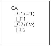
A Logic Rule whose definition is "F1 Requires F2" is invalid.
Unsatisfied Rules
Configuration rules define constraints and requirements for creating a valid configuration and notify the end user when they are violated. When a rule is violated, the configuration is considered invalid and the end user must make changes before continuing. Configurator Developer also displays a warning message when fewer than the minimum number of options are selected from one or more Features or BOM Option Classes. When this occurs, the configuration is incomplete, and the end user must select additional options to create a complete product.
A third situation can arise when the end user attempts to save a configuration session and one or more options have an Unknown (selectable) logic state, but additional selections are required to create a complete and valid configuration. When this happens, the rule containing the available options is said to be unsatisfied.
Only Logic Rules and Comparison Rules can ever be unsatisfied because they are the only rule types that, at the end of a configuration session, may contain options that are required and have an Unknown logic state.
A Logic or Comparison Rule can become unsatisfied if the rule contains the All True or Any True operators with more than one rule participant. The All True and Any True operators are explained in Using AllTrue and AnyTrue.
Note: As of Release 12.1, the term "input required" replaces "unsatisfied" in reference to rules, since the concept of unsatisfied rules does not apply to rules in Models that use the Fusion Configurator Engine, and "input required" can also apply to Models that use the configuration engine described in this document. However, Oracle Configurator Developer still refers to the Unsatisfied Message instead of the Input Required Message when defining some types of rules. (For all information about rules and the FCE, see the Oracle Configurator Fusion Configurator Engine Guide.)
Examples of Unsatisfied Rules
Unsatisfied Implies Relation
You define the following Logic Rule:
Option A Implies AnyTrue (Option B, Option C)
You also enter an unsatisfied message for the rule. At runtime, the end user selects Option A. Option B and Option C still have a status of Unknown, so the rule is unsatisfied. When the end user attempts to save the configuration, the unsatisfied rule message appears. The end user returns to the configuration session and satisfies the rule by selecting either Option B or Option C.
Unsatisfied Requires Relation
You define the following Logic Rule:
AnyTrue (Option B, Option C) Requires Option A
You also enter an unsatisfied message for the rule. At runtime, the end user selects Option A. Option B and Option C still have a status of Unknown, so the rule is unsatisfied. When the end user attempts to save the configuration, your unsatisfied rule message appears. The end user returns to the configuration session and satisfies the rule by selecting either Option B or Option C.
Unsatisfied Negates Relation
You define the following Logic Rule and provide an unsatisfied rule message:
AnyTrue ( Option A, Option B ) Negates Option C
You create a second Logic Rule with the following definition:
Option Z Negates Option C
At runtime, the end user selects Option Z. This gives Option C a status of Logic False, but both Option A and Option B are still Unknown. When the end user attempts to save the configuration, your unsatisfied rule message appears. The end user returns to the configuration session and satisfies the rule by selecting either Option A or Option B.
Unsatisfied Rule Messages
In addition to defining a violation message, you can also define a message that appears when a Logic Rule or Comparison Rule is unsatisfied. Like rule violation messages, an unsatisfied message can contain the rule name, the rule description, or any custom text that you enter.
By default, Logic and Comparison Rules do not display a message when they become unsatisfied at runtime. Therefore, an unsatisfied message is the only way to inform the end user that a rule is unsatisfied and additional options must be selected. In other words, if you do not define an unsatisfied rule message, an end user can save a configuration and will not be informed that additional selections are required.
If you choose to create a custom message, be sure to provide as much information as possible so the end user knows about the available options and how to satisfy the rule by making additional selections.
There may be times when a rule is unsatisfied but it is not necessary to display a message to the end user.
For example, you define the following Logic Rules:
All True (A, B) Implies C
X Excludes C
At runtime, the end user selects X, which makes C Logic False. To strictly satisfy Rule 1, at least one of (A, B) would have to be false. In other words, if both A and B are Unknown, Rule 1 is unsatisfied. However, the end user probably does not care whether A, for example, is false or Unknown. Therefore, Rule 1 should have Unsatisfied Message set to None.
In general, you should not specify an unsatisfied message when the rule might be unsatisfied because an option is Unknown rather than false.
Creating an unsatisfied rule message is described in Unsatisfied Message.