In this tutorial, you see how to use JDeveloper to perform offline database development. You learn to create a logical model using a UML class diagram and transform it to a physical model. You also reverse engineer database definitions into class definitions and see the limits of the reverse process.
Use the UML class diagram to model a collection of static elements such as classes and types, their contents, and relationships, as well as visually create or inspect classes, interfaces, attributes, operations, associations, generalizations and realizations. Class diagrams are used for a wide variety of purposes, from high-level conceptual models to physical data models.
 Read more...
Like other modeling artifacts data models can be used for a variety of purposes, from high-level conceptual models to physical data models. From the point of view of an object-oriented developer data modeling is conceptually similar to class modeling. With data modeling you identify entity types whereas with class modeling you identify classes.
Traditional data modeling is different from class modeling because it focuses solely on data – class models allow you to explore both the behavior and data aspects of your domain, with a data model you can only explore data issues.
As a database designer you have been asked to create a Class diagram for modeling your database objects. Using the UML class diagram, you create the logical model. After that, you transform the class diagram into a physical model. You discover how the transformer behaves and you create new datatypes and use stereotypes to take control over the transformer behavior. You see how to create multiple physical models depending on the database types you need to work with. Finally, starting from the database diagram, you reverse it into a UML class diagram and observe what differences exist with the original class diagram.
 Read more...
The class modeler can transform classes as database definitions allowing you to create stereotypes to take control over the default transformation rules natively implemented in JDeveloper.
 -
Start JDeveloper by selecting Start > All Programs > Oracle Fusion Middleware 11.1.2 > JDeveloper Studio 11.1.2
-
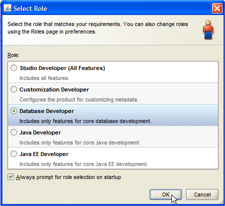
If prompted for a Role, choose Database Developer and click OK.
Close the Tip of the Day window.
Once loaded, the JDeveloper IDE appears. Read more...
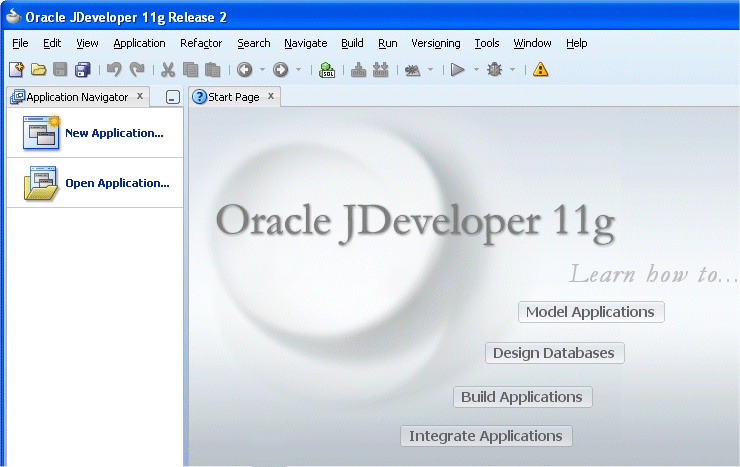
The very first time you open JDeveloper, the Start Page displays. Notice the various options available to help you learn about JDeveloper. After exploring these options, click the X on the Start Page tab to close it. (the X appears when you mouse over the tab).
You can re-invoke the Start Page later by choosing Help | Start Page.
-
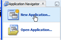
In the Applications Navigator, click New Application.
-
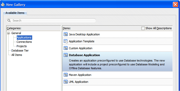
In the New Gallery, select General | Applications and choose Database Application as the Item.
Click OK.
-
In the Create Database Application dialog, change the Application Name from Application1 to DBModeling and type oracle as the Application Package Prefix. Notice that the Directory Name automatically changes to match the new Application Name.
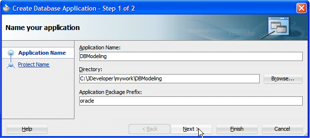
Then click Next.
-
In Step 2 of the Wizard enter LogicalModel as the Project Name and select Database Modeling from the Project Features pane.
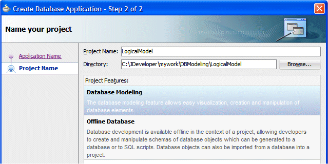
Click Finish.
-
The Application Navigator should look like the following:
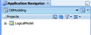 When you work in JDeveloper, you organize your work in projects within applications.
 Read more...
JDeveloper provides a number of predefined templates which enable you to create applications and projects that are configured for developing different types of applications.
The templates provide the environment for the basic range of technologies supported by JDeveloper. You create your working environment by selecting the template that best fits your needs and then configuring it to add any additional technologies you intend to use.
The options available to you in the New Gallery and for some context menu operations, depend on your template selection for that application. -
Save your work by clicking Save All
 . You should save your work at regular intervals as you progress through the rest of the tutorial.
In this section, you set preferences for the class diagram environment. You can customize the way the class diagram components appear and respond to your specific needs. To prepare the class diagram environment, perform the following steps:
-
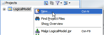
Right-click the LogicalModel project in the Application Navigator and choose New from the context menu to display the New Gallery.
-
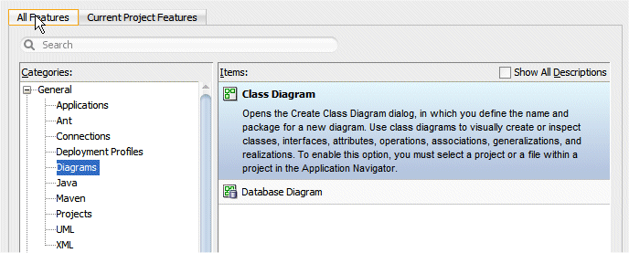
In the New Gallery, click the All Features tab and in the Categories list, expand the General node if it is not already expanded, and select Diagrams. Then select Class Diagram from the Items list and click OK.
-
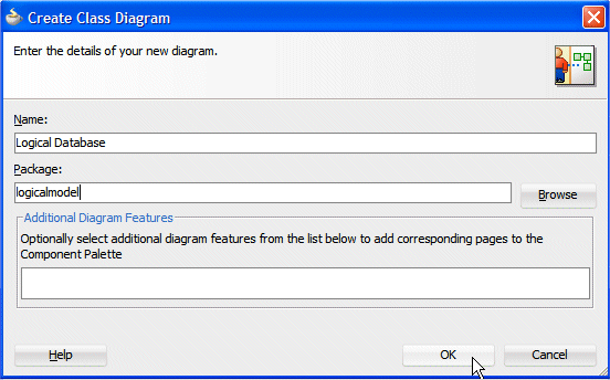
In the Create Class Diagram dialog, change the Name to Logical Database and the Package name to logicalmodel, then click OK.
A new database diagram opens.
-
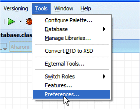
To set some class diagram preferences, select Tools -> Preferences.
-
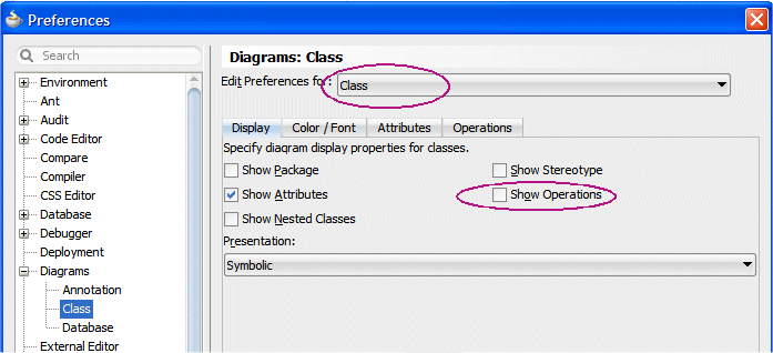
In the Preferences dialog, select Diagrams -> Class, then in the Edit Preferences for, choose Class, and uncheck Show Operations as you are doing logical DB modeling and you don’t need operations.
-
In the same dialog, click the Attributes tab, and check Show Visibility and turn off Sort Alphabetically.
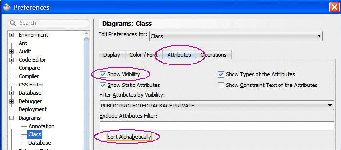
Click OK. These preferences are now set for all Class diagrams.
-
Click the Save All button
 to save your work.
 -
Notice the Component Palette to the right of the diagram area. You can use the Component Palette to add classes and related elements to your class diagram.
(If the Component Palette is not visible, open it by choosing View | Component Palette from the main menu.)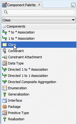
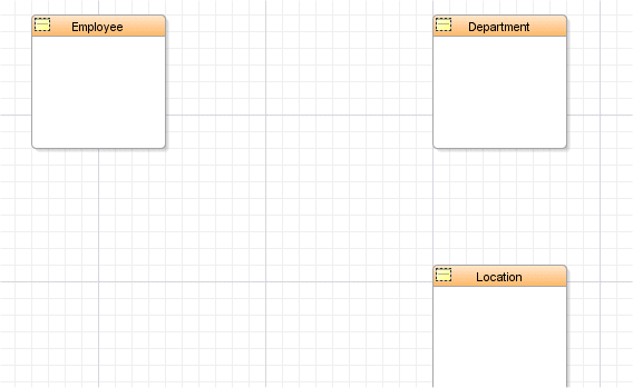
The following image shows the classes you are about to create: Employee, Department, and Location.
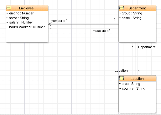
To create the above diagram, perform the following steps:
-
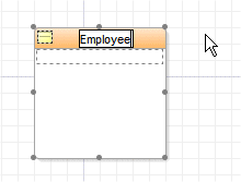
In the Component Palette, select the Class component
 and drag and drop it it onto the diagram.
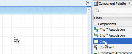
-
Change the name to Employee.
-
Repeat the above operation to create 2 additional classes named Location and Department.
-
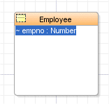
Using 'in place' edit, add attributes to the classes. Click inside the Employee class to create an attribute placeholder, (the new item will be blue), click again to enter edit mode (don’t double click) and over-write the existing text with empno : Number.
-
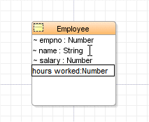
Repeat the above operation to create the attributes per the following image (name: String, salary: Number and hours worked: Number)
-
Double-click within the Employee class to edit the properties. Expanding the Owned Attribute node shows the created attributes.
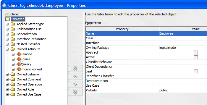
-
Expand the node of one of the attributes, for example the empno node and explore the various definable properties.
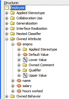
Click OK to exit.
-
In the Component Palette, click the Directed 1 to * Association icon
 , then click within the Department class and keeping pressed, draw a line to the Employee class and click.
 Association between classes is bi-directional by default.
 Read more...
You can define the flow of the association by using a directed association. The direction of the arrowhead identifies the container-contained relationship. -
Double-click the association to open the Properties dialog and expand the Owned End node. Rename endDepartment as made up of, and rename the endEmployee as member of.
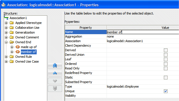
Click OK.
-
Your diagram should look like the following:

-
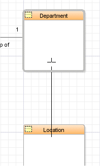
Create a * to * Association
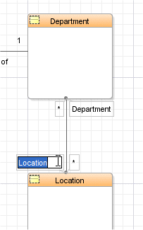
 between Location and Department, and using 'in place' edit this time, rename the ends department and location. Refer the the previous steps if you need help.

-
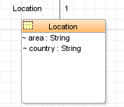
Using 'in place' edit, within the Location class, add 2 attributes area : String and country : String.
-
Double-click the Department class to open the Properties dialog.
-
Select the Owned Attribute node and click the Add button
 . Select the Property option from the list.
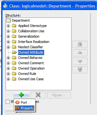 The Port option is a a specialization of the Property option.
 Read more...
The Port option is part of the UML standard specification. It is not used in Class attributes, but as it is part of the UML specification it is listed as an option here.
-
In the Properties pane, type group as the Name and String as the Type.
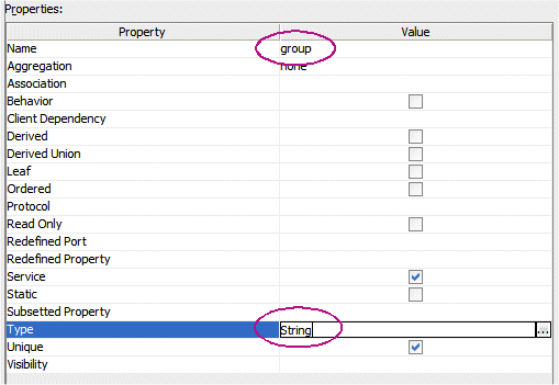
-
Repeat the same operations to add a new attribute named name and of type String.
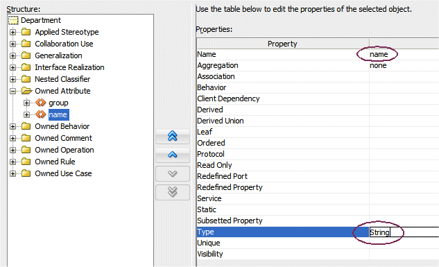
Click OK.
-
Click the Save All button
 to save your work.
 -
Your diagram should look like this:

Employees are either full time employees or part time employees. Hours worked only concern part time employees. You want to represent these categories of employees on your class diagram using Generalization. You see that Generalization can be represented in different ways.
To enhance the diagram with categories of employees, perform the following steps:
-
Select Employee and resize it to enlarge the box.
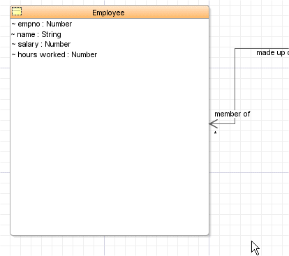
-
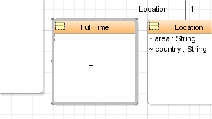
From the Component Palette, add a new Class
 to the diagram and name it Full Time.
-
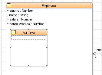
Select the Full Time class and move it within the Employee class.
-
Using the Generalization
 icon from the Component Palette, draw a line from the Full Time class to the Employee class.
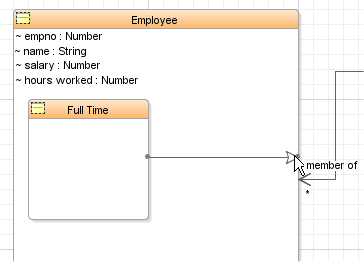 In UML modeling, a generalization relationship is a relationship in which one model element (the child) is based on another model element (the parent).
 Read more...
You can add generalization relationships to capture attributes, operations, and relationships in a parent model element and then reuse them in one or more child model elements.
Because the child model elements in generalizations inherit the attributes, operations, and relationships of the parent, you must only define for the child the attributes, operations, or relationships that are distinct from the parent.
The parent model element can have one or more children, and any child model element can have one or more parents. It is more common to have a single parent model element and multiple child model elements. -
From the Component Palette, create a new Class
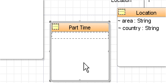
 on the diagram and name it Part Time.
-
Using the Generalization
 icon from the Component Palette, draw a line from the Part Time class to the Employee one. The two generalizations represent the possible ways an employee may work.
 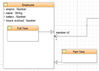 Employee is the generalization class for Part Time and Full Time.
 Read more...
You can also implement this concept in a 'Database oriented representation' using subtypes within the Employee class.
Even if the model can accept having a mixed representation of generalization using in and out combination, it is recommended to choose a convention ('all in' or 'all out') and stick with it consistently to make the models more readable.
-
Select the Part Time class and drop it within the Employee one. From the previous representation, the two subclasses within the super-class is just a visual effect. There is no semantic change to the model.
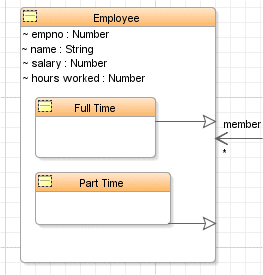
In database modeling terminology these are known as two subtypes of Employee.
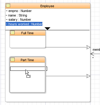
Since only Part Time employees are concerned by the hours worked attribute, select it and drag it within the Part Time sub category.
-
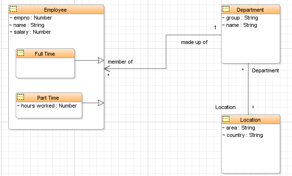
Your diagram should now look like the following:
-
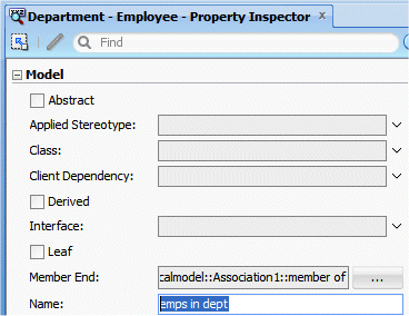
Select the directed association between Employee and Department, and in the property Inspector, check the Display Options: Show Name. This displays the Association name (Association1) on the diagram.

-
In the property Inspector, type emps in dept as the name.
-
Select the association between Department and Location and check the Show Name option in the property inspector.
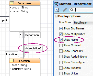
-
This time, using 'in place' edit, rename the association to department locations.
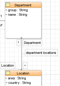
-
Your diagram should now look like the following:
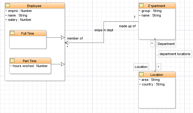
-
Click the Save All button
 to save your work. Your Logical class model is defined now.

 Part 2: Transforming the Logical Model into Database Physical Models
