| C H A P T E R 7 |
|
Sample Switch Configurations for Multiple Tenants |
This chapter contains the following sections:
|
Note - If you reset the switch while you are performing the instructions in this section, you must save the configuration first. If you do not, you will lose all of your changes. To save the configuration, follow the instructions in Section A.9, Saving Your Switch Settings. |
This chapter is intended mainly for Internet Service Providers (ISPs) who need to:
The chapter provides two sample switch configurations that illustrate the use of VLANs to allocate server blades to different customers. We shall refer to an ISP's customers in the rest of the chapter as the "tenants" of particular server blades.
The switch configurations assume that only the ISP has login and password access to the SC and switch command-line interfaces. Customers of the ISP can ping the NETMGT port on the switch, because they have their own management networks that include the NETMGT port. But unless you give them login and password access to the switch, they cannot access it. The VLAN configuration means that none of the customers has access to the SC's network port via telnet.
Although this chapter is intended mainly for ISPs, it might also be useful to network administrators with a general interest in ways of using VLANs to control network traffic on the Sun Fire B1600 blade system chassis.
This chapter does not provide instructions on configuring IPMP on the blades. For guidance with the configuration of the IPMP interfaces for complex VLAN setups, see Chapter 6.
For information about configuring the switch to remove VLAN tagging from frames that it sends onto the network (but to add a VLAN tag to untagged frames that it receives from the network), see Section 7.2.4, Allocating Data Network Ports to Each Tenant and Section 7.3.4, Sharing the Data Network Ports Between Tenants.
In this scenario, an Internet Service Provider (ISP) is assumed to own the blade system chassis and to be in overall responsibility for managing it. The ISP therefore has sole access to the switch's command-line interface on NETMGT.
The scenario also assumes three tenants: Tenant 1, Tenant 2, and Tenant 3. Each tenant has a single data VLAN assigned to him or her exclusively. This data VLAN includes a number of server blades (that is to say, a number of the switch's server blade down-link ports) and a number of external data ports.
The tenants also have a management VLAN each that gives them secure access to their own blades.
The switch configuration is summarised in TABLE 7-1.
The rest of this section tells you how to create the configuration described in TABLE 7-1. It is divided into the following sub-sections:
 [ D ]
[ D ]
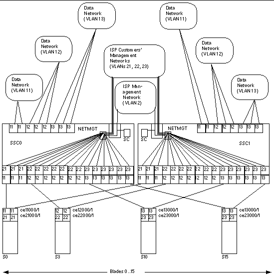
FIGURE 7-1 is a diagram expressing the same information as TABLE 7-1. At the center is the ISP's management VLAN, VLAN 2. This VLAN is exclusive to the ISP's network administrator. It includes the NETMGT port on the switch (thereby allowing the ISP network administrator to configure the entire switch via a telnet or web connection). It also includes the System Controller (thereby allowing the ISP to configure the entire chassis and to access the consoles of all server blades and both switches from the sc> prompt). Note, however, that the System Controller's membership of the VLAN is configured from the sc> prompt (specifically, by the setupsc command): it is not part of the switch configuration process.
Above VLAN 2 in the diagram are the three management VLANs for the ISP's individual customers. Each of these customers has access on a dedicated management VLAN to his or her own server blades. So, for example, Tenant 1 (whose management VLAN is number 21) can telnet into the server blades in slots 0, 1, and 2. Tenant 2 (management VLAN 22) can telnet into the server blades in slots 3 through 9. And Tenant 3 (management VLAN23) can telnet into slots 10 through 15.
At the bottom of the diagram, the first of each customer's server blades is shown. These blades each require two logical interfaces to their data network and two logical interfaces to their management network. These logical interfaces have to be provided by IPMP (see Chapter 6). The diagram shows the interface numbering required for the IPMP configuration. For example, Tenant 1's server blades contain two logical interfaces for VLAN 11 (data network) and two logical interfaces for VLAN 21 (management network). Following the formula provided in Chapter 6, the interface numbering for each of Tenant 1's blades is ce11000 and ce21000 (for the connection on ce0 to the switch in SSC0) and ce11001 and ce21001 (for the connection on ce1 to the switch in SSC1).
Finally the ISP's customers in this scenario each have dedicated network uplink ports. Tenant 1 has NETP0 and NETP1, Tenant 2 has NETP2, NETP3, and NETP4, and Tenant 3 has NETP5, NETP6, and NETP7. These ports are made exclusive to particular tenants by being included in the data network VLANs that contain the server blades belonging to each tenant. So, for example, Tenant 3's data network VLAN (13) includes server blade ports SNP10 through SNP15 plus the uplink ports NETP5, NETP6, and NETP7.
|
Note - If the uplinks belonging to the different tenants connect to the same external switch, then the Spanning Tree protocol will break some of the connections. We recommend you use a different external switch for each tenant. Alternatively you can turn off the Spanning Tree protocol (see Section 7.2.5, Turning Off Spanning Tree). |
1. To log into the switch in SSC0, type:
2. When prompted for a user name, type admin.
Type admin again as the password.
3. Make sure that the switch is using the factory default configuration.
For information about how to do this, see Section A.5, Restoring the Switch to its Factory Default State.
4. If you have returned to the factory default configuration, or if you have not yet set your own password, do so now.
For information about how to do this, see Section 2.2, Logging into the Switch as the Default User and Setting the Passwords.
5. Create and give names to the tenants' data VLANs.
6. Create and give names to the tenants' management VLANs.
1. Configure the switch's management port (NETMGT) to enable it to receive and transmit frames from and to the ISP's management VLAN (2) and all of the tenants' management VLANs (21, 22, 23).
The ISP uses the default management VLAN, VLAN 2.
The meaning of this sequence is as follows:
2. Make sure the switch's IP packet filter is configured to permit traffic to pass from the server blades to the management network.
For information on how to do this, see Section A.12, Enabling Secure Management of Blades.
1. For Tenant 1, configure the server blade ports so that they will transmit and receive frames tagged for VLANs 11 and 21 only.
Repeat these commands for the other two server blade ports (SNP1 and SNP2) belonging to Tenant 1.
2. For Tenant 2, configure the server blade ports so that they will transmit and receive frames tagged for VLANs 12 and 22 only.
Repeat these commands for the other server blade ports (SNP4 through SNP9) belonging to Tenant 2.
3. For Tenant 3, configure the server blade ports so that they will transmit and receive frames tagged for VLANs 13 and 23 only.
Repeat these commands for the other server blade ports (SNP11 through SNP15) belonging to Tenant 3.
1. Configure the network ports for Tenant 1 so that they will receive and transmit frames tagged for VLAN 11 only.
Repeat these commands for NETP1.
2. Configure the network ports for Tenant 2 so that they will receive and transmit frames tagged for VLAN 12 only.
Repeat these commands for NETP3 and NETP4.
3. Configure the network ports for Tenant 3 so that they will receive and transmit frames tagged for VLAN 13 only.
Repeat these commands for NETP5, NETP6, and NETP7.
If the uplinks belonging to the different tenants connect to the same external switch, then the Spanning Tree protocol will break some of the connections. We recommend you use a different external switch for each tenant. Alternatively you can turn off the Spanning Tree protocol. To turn off Spanning Tree, type:
To do this, follow the instructions in Chapter A.
2. Copy the switch configuration onto the second switch.
To do this, follow the instructions in Chapter A.
In this scenario, there is an Internet Service Provider (ISP) who is assumed to own the blade system chassis and to be in overall responsibility for managing it. There are also two tenants, Tenant 1 and Tenant 2. Both tenants have a data VLAN assigned to them, and the VLAN includes eight server blades (that is to say, eight of the switch's server blade ports) plus four of the switch's external data ports. In other words, the two tenants share four of the external data ports (neither has exclusive use of them).
The configuration of the switch for this scenario is summarised in TABLE 7-2.
The rest of this section tells you how to create the configuration described in TABLE 7-2. It is divided into the following sub-sections:
 [ D ]
[ D ]
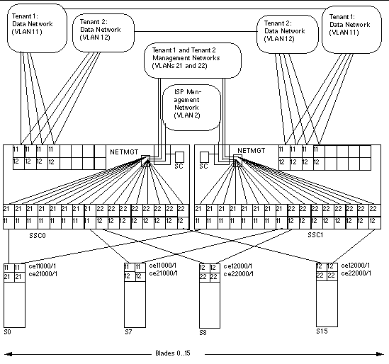
FIGURE 7-2 is a diagram expressing the same information as TABLE 7-2. In this scenario the principles are the same as in scenario A except that all of the network uplink ports are shared by the tenants of the server blades. In other words, both of the tenants' data VLANs (VLAN 11 for Tenant 1, and VLAN 12 for Tenant 2) include the uplink ports NETP0 through NETP3. This does not result in the tenants receiving data from each other's server blades, because any frames that leave ports NETP0 through NETP3 will be tagged for either VLAN 11 (Tenant 1) or VLAN 12 (Tenant 2).
1. Create and give names to the tenants' data VLANs.
Console#configure Console(config)#vlan database Console(config-vlan)#vlan 11 name tenant1 media ethernet Console(config-vlan)#vlan 12 name tenant2 media ethernet |
2. Create and give names to the tenants' management VLANs.
1. Configure the switch's management port (NETMGT) to enable it to receive and transmit frames from and to the ISP's management VLAN (2) and both of the tenants' management VLANs (21 and 22).
2. Make sure the switch's IP packet filter is configured to permit traffic to pass from the server blades to the management network.
For information on how to do this, see Section A.12, Enabling Secure Management of Blades.
1. For Tenant 1, configure the server blade ports so that they will transmit and receive frames tagged for VLANs 11 and 21 only.
Repeat these commands for the other seven server blade ports (SNP1 through SNP7) belonging to Tenant 1.
2. For Tenant 2, configure the server blade ports so that they will transmit and receive frames tagged for VLANs 12 and 22 only.
Repeat these commands for the other seven server blade ports (SNP9 through SNP15) belonging to Tenant 2.
1. Configure the network ports so that they will receive and transmit frames tagged for VLAN 11 and VLAN 12.
2. Repeat these commands for NETP1 through NETP3.
To do this, follow the instructions in Chapter A.
4. Copy the switch configuration onto the second switch.
To do this, follow the instructions in Chapter A.
Copyright © 2004, Sun Microsystems, Inc. All rights reserved.