Chapter 4 Creating and Managing Rules
This chapter describes:
-
Packet filtering rules
-
Viewing and Editing the details of an object in the Packet Filtering table
-
Editing a rule
-
Adding a rule
-
Reordering rules
-
Deleting rules
-
Administrative access rules
-
Network Address Translation (NAT)
-
Virtual Private Network (VPN)
-
Verifying a policy
The following information describes using the administration GUI. Appendix A contains information about the command line interface.
Packet Filtering Rules
To View and Edit the Details of an Object
-
Click on the cell in the Packet Filtering Table containing the object you want to view or edit. The dialog window for the chosen object appears.
To Edit a Rule
Click and highlight the name of the policy whose rules you want to edit in the Policies List page.
-
Click the Edit button.
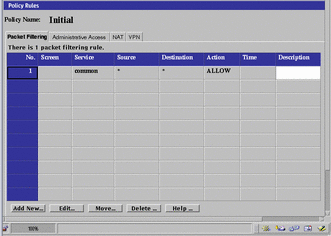
The Policy Rules page appears.
Figure 4-1 Policy Rules Area of the Policy Rules Page
-
Click the Packet Filtering tab in the Policy Rules area.
-
Click and highlight the rule to edit.
-
Click the Edit... button.
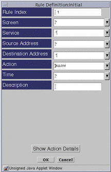
The Rule Definition dialog window for the selected policy appears.
Figure 4-2 Rule Definition Dialog Window with Show Actions Button
-
Edit each field by clicking the down arrow to display the choice list.
You can add a new address, range of addresses, or list of addresses for both the Source and Destination addresses.
-
(Optional) Click the OK button in the Rule Definition dialog window when you have finished editing the rule.
-
(Optional) Click the Verify Policy button at the top of the Policy Rules page to ensure that you have created a valid policy.
-
Click the Save Changes button to be sure the changes are saved.
Note -Each Save creates a Version.
To Add a New Rule
-
Click the Add New... button in the Policy Rules area of the Policy Rules page.
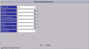
The Rule Definition dialog window for the selected policy appears.
Figure 4-3 Rule Definition Dialog Window
-
Edit each field by clicking the down arrow to display the choice list.
-
Click the OK button when you have finished editing the rule.
-
(Optional) Click the OK button in the Rule Definition dialog window when you have finished editing the rule.
-
(Optional) Click the Verify Policy button at the top of the Policy Rules page to ensure that you have created a valid policy.
To Move a Rule
-
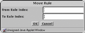
Click the Move button to display the Move Rule dialog window.
Figure 4-4 Move Rule Dialog Window
-
Type the number of the rule that you want to move in the From Rule Index field.
-
Type the number of the position to which you want to move the rule in the To Rule Index field.
-
Click the OK button.
The rules reorder themselves to reflect the change you made. You must move each rule whose position you want to change.
-
Click the Verify button below the Rules area to confirm that the rules will work when you activate this policy.
-
(Optional) Click the OK button in the Rule Definition dialog window when you have finished editing the rule.
-
(Optional) Click the Verify Policy button at the top of the Policy Rules page to ensure that you have created a valid policy.
-
Click the Activate button in the Policy List page to activate this policy
Note -Edits do not affect the behavior of the SunScreen until you activate the policy.
To Delete a Rule
Note -
Do not delete all the packet filtering rules or you may lose all access to the Screen.
-
Select the rule you want to delete from the table in the Packet Filtering area.
-
Click the Delete... button.
The Delete Rule dialog window appears.
Figure 4-5 Delete Rule Dialog Window

-
Click the Yes button.
Administrative Access Rules
You use the Administrative Access Rules tab to:
-
Provide access to the Screen from additional remote Administration Stations
-
Provide access from the administration GUI for Local Administration.
You can add new users that you have created, re-add users for whom new passwords have been defined, or SecurID assigned names on this page. You add user, create and change passwords, and change SecurID names. Also, you can add an Access Rule for users, and change the encryption parameters.
You must activate a new policy for any changes to take effect.
The fields of the Administrative Access Rules tab are described in the SunScreen Reference Manual.
The following information describes using the administration GUI. Appendix A contains information about the command line interface.
To Add an Administrative Access Rule for Local Administration
-
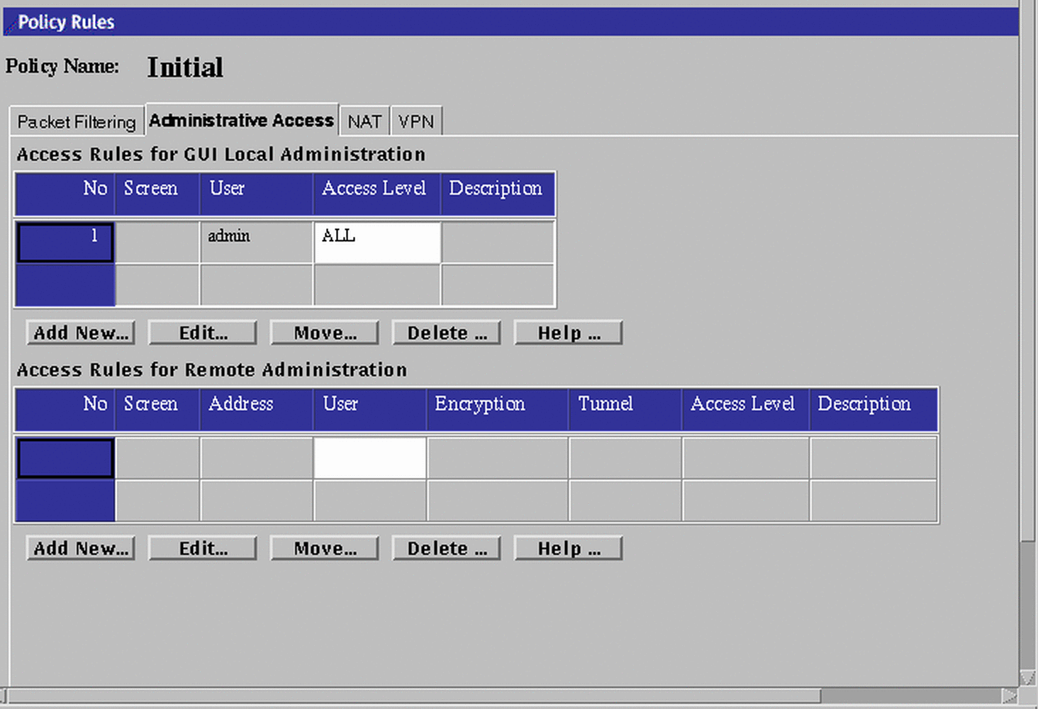
Click the Administrative Access tab in the Policy Rules area of the Policy Rules page to move to the Administrative Access area.
Figure 4-6 Administrative Access Area
-
Click the Add New... button, or Edit button, below the Access Rules for GUI Local Administration area.
The Local Access Rules dialog window appears.
Figure 4-7 Local Access Rules Dialog Window
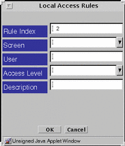
In the Administrative Access definition dialog window, there are different fields for local and remote administration.
The fields for Local Administration are:
-
Rule Index, the order in which access is checked. If a user is included in multiple Access Rules (explicitly or as a member of a Group), the first entry will be the one to determine the user's Access Level.
-
Screen entry limits application of the Access Rule to only the named Screen.
-
User is the user or group of administration users to which this Access Rule applies.
-
Administrative Access Level:
-
Status Administrators, who have the access level STATUS can only monitor SunScreens, but cannot view the policies.
-
Local Administrators, who have the access level READ, are users responsible for reviewing their individual Screen's policy. Local Administrators are allowed to read policies, but cannot change policies, so they must make a request for changes to Executive or Master Administrators.
-
Executive Administrators, who have the access level WRITE, can define and change policies.
-
Master Administrators, who have the access level ALL, grant the various access levels to the other administrators.
-
-
Description field entry is useful for notes
To Add an Administrative Access Rule for Remote Administration
If you are adding an additional remote Administration Station, you must add a rule for it. Make a note of the encryption parameters you are using, these parameters have to match the encryption parameters on the remote Administration Station.
-
Click the Administrative Access Rules tab in the Policy Rules area.
-
Click the Add New... button in the Access Rules for Remote Administration area.
The Remote Access Rule dialog window appears.
Figure 4-8 Remote Access Rules Dialog Window
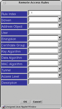
Encryption can have two values: SKIP_VERSION_1, and SKIP_Version_2.
-
Click the down arrow on the Screen field to display the choice list of Screens.
Perform this step only if you want to associate this entry with a specific screen.
Note -If you are using the Centralized Management Group feature, and this field is left blank, or with a "*" in it, the Access Rule being defined will allow, by default, access to all of the Screens in the cluster.
-
Click the down arrow on the Address Object field to display the choice list of addresses.
-
Click and highlight the address that you want to use.
Type the authorized user name in the User field.
-
Click the down arrow on the Encryption field to display the choice list of the versions of SKIP and highlight the version of SKIP that you want to use.
SKIP_VERSION_1 is used for communicating with an SPF-100.
-
Click the down arrow on the Certificate Group field to display the choice list of certificate groups and highlight the certificate group that you want to use.
Specify the Screen's certificate or certificate group (in this case, the Certificate or Certificate Group that includes the Remote Administration Station's certificate) and Administration IP address in the Screen's Administration Certificate field.
-
Click the down arrow on the Key Algorithm field to display the choice list of key algorithms and highlight the key algorithm that you want to use.
-
Click the down arrow on the Data Algorithm field to display the choice list of data algorithms and highlight the data algorithm that you want to use.
-
If you are using SKIP_VERSION_2 only, click the down arrow on the MAC Algorithm field to display the choice list of MAC algorithms and highlight the MAC algorithm that you want to use.
-
Click the down arrow on the Tunnel field to display the choice list of tunnel addresses and highlight the tunnel address of the Remote Administration Station.
-
Enter a description in the Description field.
-
Click the down arrow on the Access Level field to display the choice list of the access levels and highlight the level of access that you want this user to have.
There are four access levels for remote administrators:
ALL STATUS READ WRITE NONE (Default)
-
Click the OK button.
-
Repeat the previous steps until you have added all the access rules for remote administration through the administration GUI, as required.
-
Click the Save Changes button.
-
Add the Screen's certificate MKID in the SKIP database of the Remote Administration Station and configure it to use SKIP to communicate with the Screen.
To Edit an Administrative Access Rule for Remote Administration
If you change the encryption parameters, make a note of them before the changes because they have to match the encryption parameters on the remote Administration Station.
Perform the following steps to make any changes through the administration GUI:
-
Click the Administrative Access tab in the Policy Rules panel to display the Access Rules page.
-
Click and highlight the rule that you want to edit in the Access Rules for Remote Administration panel then click the Edit button.
The Access Rules applet window appears with the values for that rule.
-
Click the down arrow on the Address field,to display the choice list of addresses and highlight the address you want to use.
-
Type the Authorized User in the User field.
-
Click the down arrow on the SKIP Version field to display the choice list of the versions of SKIP and highlight the version of SKIP you want to use.
-
Click the down arrow on the Certificate Group field to display the choice list of certificate groups and highlight the Certificate Group that you want to use.
Choose the Certificate Group containing the Remote Administration station's Certificate, not the Group that contains the Screen's certificate.
-
Click the down arrow on the Key Algorithm field to display the choice list of key algorithms and highlight the algorithm you want to use.
-
Click the down arrow on the Data Algorithm field to display the choice list of data algorithm and highlight the algorithm you want to use.
-
Click the Save button
Network Address Translation (NAT) Rules
Note -
You can use NAT with SKIP to provide communication in an encrypted tunnel (secure virtual private network). The encryption at the source tunnel address must take place after the NAT mapping and decryption at the destination tunnel address must take place before the NAT translation.
The following information describes using the administration GUI. Appendix A contains information about the command line interface.
NAT Mapping Overview
You use the NAT tab to set up mapping rules that translate IP addresses according to specific rules. These rules interpret the source and destination address of incoming IP packets, then translate either the apparent source or the intended destination, and send the packets on. You can map hosts, lists of addresses, ranges of addresses, or specific groups, depending on what you have configured in your SunScreen installation.
Rules make up the map that is used during the translation of a packet. In general, you would translate addresses to:
-
Ensure that internal addresses appear as registered addresses on the Internet
-
Send traffic for a specific destination to a different, pre-determined destination.
When defining NAT rules, the first rule (lowest number) that matches a packet applies, and no other rules can apply. Therefore, you might define specific rules first, then broader cases later.
You can define the mappings of internal addresses to external addresses. Use the NAT tab in the Policy Rules area of the Policy Rules page to specify the address that is to be translated to a particular address, and to select whether you want static mapping or dynamic mapping. Additional information on NAT is in the SunScreen Reference Manual.
All network address translations happen before a packet is tested against any of the screening rules. In this way, you can define all screening rules using only internal addresses. The four addresses NAT supports are:
-
Source
-
Destination
-
Translated Source
-
Translated Destination
NAT Administration Page
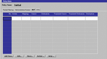
The meanings and uses of the specific fields in the NAT page are as follows:
Table 4-1 NAT Page Field Explanations
All NAT rules are unidirectional. They work precisely as defined and are not interpreted as also applying in the reverse direction. So, if you map an internal source address to an external source address, and you want the mapping to apply in the reverse direction, you must map the external destination address to the internal destination address with a second rule.
Your NAT Scenario
When building security policies using NAT, define the security policy rules in terms of internal addresses. All packets that are destined for external addresses used in NAT must be routed to the Screen.
Note -
If you use static NAT to map a machine's address, a machine on any other network can initiate traffic to that machine, given a properly-defined reverse rule.
Because in routing mode (unlike stealth mode), the Screen does not automatically answer ARP requests for destination address, the Screen must either route to a separate network that has a destination address, or an ARP request must be added manually.
Static NAT is a one-to-one mapping of the internal address to an external address, and dynamic NAT is many-to-one or many-to-few mapping of internal addresses to an external address.
For more information on NAT and the possible set up, see the SunScreen Reference Manual.
Note -
Do not include the address of a remote Administration Station in any of your NAT rules, where NAT will occur between the Administration station and the Screen.
Note -
If Centralized Management is in place, each NAT rule must be associated explicitly with the Screen to which it applies.
To Add ARP Manually on a Screen in Routing Mode
Type the following if the networks that attach to the Screen on the inside have NAT mappings applied, including any network on which there are addresses to which you want to allow public access:
# arp -s IP_Address ether_address pub |
Note -
You must add this entry each time that you reboot the Screen, so you may want to modify a Startup script to do this automatically when you reboot. This is not necessary in stealth mode.
To Define NAT Rules
When defining a static NAT mapping, be sure that:
-
The ranges and groups used in the Source and Translated Source fields are exactly the same size.
-
The ranges and groups used in the Destination and Translated Destination fields are exactly the same size.
-
Select the NAT tab in the Policy Rules area of the Policy Rules page to move to the Network Address Translation area.
Figure 4-9 Network Address Translation Area
-
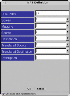
Click New... in the Add New... choice list below the Network Address Translation area to display the NAT Definition dialog window.
Figure 4-10 NAT Definition Dialog Window
-
Select the Screen that should use NAT mapping.
Default is NAT available for all Screens.
-
Select all four addresses in the NAT Definition dialog window.
-
Click the OK button.
-
Repeat the previous steps until you have edited all the rules as required.
-
Click the Save Changes button to save the edited mappings to a file.
You must click the Activate button for the changes take effect.
In most cases, when defining a static mapping, the internal address and external address are each a single address.
To Edit the NAT Rules
-
Select the NAT tab in the Policy Rules area of the Policy Rules page to move to the Network Translation area.
-
Click the Mapping field to choose the mapping on the table that you want to edit.
-
Click the Edit button below the Network Address Translation area to display the NAT Definition dialog window for that mapping.
-
Click the down arrow on the Mapping field to display the list of mappings.
-
Click and highlight the type of mapping that you want.
In most cases when defining a static mapping, the Source Address and Destination Address are each a single address.
-
Click the down arrow on the Source Address field to display the list of addresses.
-
Click and highlight the address that you want.
The new source address appears in the Source Address field.
-
Click the down arrow on the Destination Address field to display the list of addresses.
-
Click and highlight the address that you want.
-
Click and highlight the translated source that you want.
-
Click and highlight the translated destination that you want.
The new destination address appears in the Destination Address field.
-
-
Click the OK button of the NAT Definition dialog window to save your edits.
-
Repeat the previous steps until you have edited all the mappings as required.
-
Click the Save Changes button to save the edited mappings to a file.
You must click the Activate button for the changes take effect.
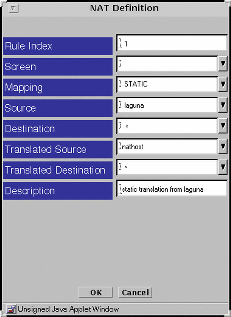
Example: Static NAT of a Host to a Host
The following example translates the address of laguna to nathost for all destination addresses for all outgoing traffic.
Figure 4-11 Static Translation of a Host To a Host
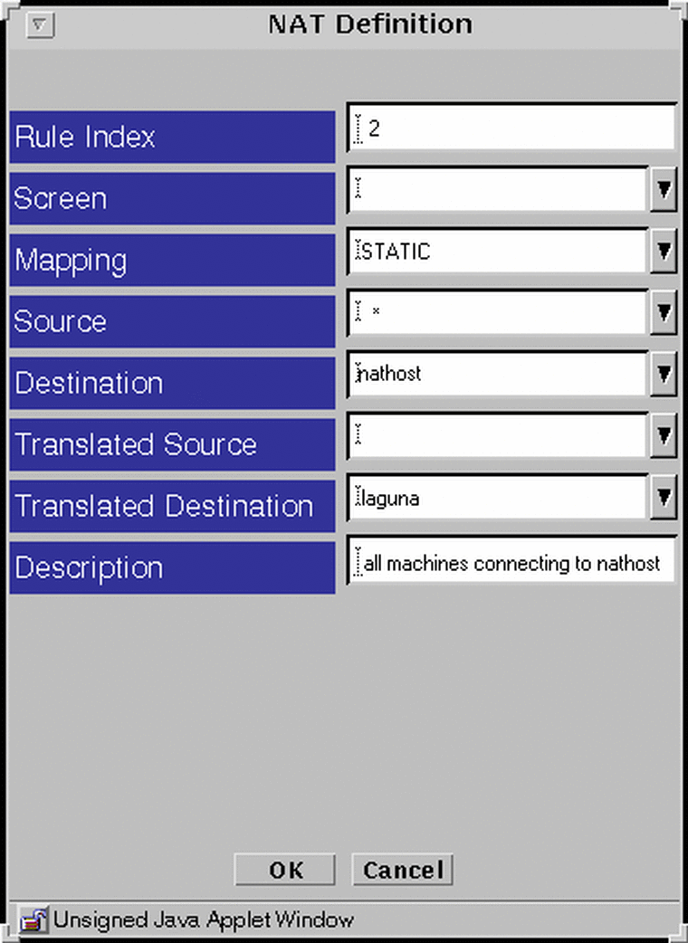
Example: Reverse Rule
The following example translates the address nathost to laguna for all source addresses for all incoming traffic. One-way communication is allowed, so one of these rules may be used without the other.
Figure 4-12 The Reverse Rule
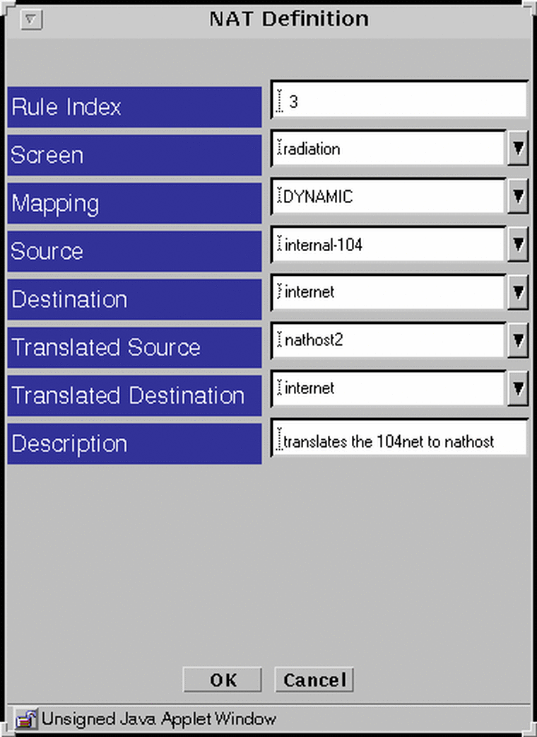
Example: Dynamic Translation of a Range Of Addresses to One Host
In the following example, the translation occurs only when the destinations match what is in the internet address group. If the address was not in this group, the source address would not be translated.
Figure 4-13 Dynamic Translation
Virtual Private Network (VPN) Rules
When you configure a Screen to use a Virtual Private Network (VPN) between two locations, all packets traveling from one location to another are encrypted and encapsulated before they are sent over the public internetwork. A VPN ensures that the contents of the packets remain private, and conceals the topology of the internal network.
The packet contents remain private because anyone capturing packets between the two locations sees only unreadable, encrypted packets. When these packets arrive at the remote location the Screen decrypts them and forwards them to their final destination in a readable form.
A VPN conceals the details of its network topology by encrypting the original packets (including their IP headers) and creating new IP headers using addresses specified by the VPN Gateways. When these packets arrive at the remote location, the Screen removes the new IP headers, and after decrypting the packets, restores the original headers so the packets can reach their final destination.
A VPN is typically used when companies have offices in more than one location. Such companies often want to use public networks for a secure private network, and avoid the need for dedicated lines or any changes to their user applications.
Before You Begin
Before you configure a VPN, you must complete several preliminary tasks including the following:
-
Install the SunScreen software on all Screens involved in the VPN. For detailed information on Screen installation, refer to the SunScreen 3.1 Installation Guide.
-
Each Screen must have with its own local certificate. If you installed a Screen with Remote Administration, this certificate was automatically generated. If not, you can refer to "To Generate Screen Certificates" on page 87 of this manual for details on how to create this certificate.
-
Add a certificate object to each Screen for every other Screen in the VPN. For more information on adding certificates, refer to"To Associate Certificate IDs" on page 91 of this manual.
-
Create Address objects (host, group or range) on each Screen for any address in the VPN; including an Address object for each screen as well. Refer to "Address Objects" on page 61 of this manual for more information.
Once you successfully complete these tasks, you set up the VPN by defining VPN gateways and creating packet filtering rules as described in the following sections.
Configuring a VPN
You need to create a "VPN Gateway" for each Screen involved in the VPN to define the systems that are taking part in a particular VPN. You create these Gateway definitions are using the VPN tab in the Policy Rules area of the Policy Rules page.
Each VPN Gateway definition associates a particular certificate with a set of hosts that are "protected" by that gateway. The protected hosts will have their traffic encrypted/decrypted by that certificate. In addition, the defined gateways are associated with each other by giving them each the same VPN name.
To Add a VPN Gateway Definition
To Add a VPN Gateway definition, perform the following steps:
-
Click the VPN tab in the Policy Rules area of the Policy Rules page.
-
Click the Add New... button in the VPN area.
The VPN Definition dialog window appears.
-
In the Name field, type the name of the VPN to which the gateway belongs.
Type the same name for each gateway included in the VPN.
-
Click the down arrow in the Address field to select the machine to be included in the VPN.
-
Click the down arrow in the Certificate field to select the gateway's Certificate ID.
-
Click the down arrow in the Key Algorithm field to select the key algorithm (or "none") to be used by the VPN.
All gateways in the same VPN must use the same key algorithm.
-
Click the down arrow in the Data Algorithm field to select the data algorithm (or "none") to be used by the VPN.
All gateways in the same VPN must use the same data algorithm.
-
Click the down arrow in the MAC Algorithm field to select the MAC algorithm (or "none") to be used by the VPN.
All gateways in the same VPN must use the same MAC algorithm.
-
Click the down arrow in the Tunnel Address field to select the tunnel address to be used by the VPN.
-
(Optional) Type a description of the VPN gateway.
-
Click the OK button.
Note -Repeat steps 2 through 11 to define a VPN Gateway for each Screen in the VPN. Be sure to give each of them the same VPN name to include them all in this particular VPN.
To Create Packet Filter Rules to Use a VPN
Once you define the VPN by creating VPN Gateways, you must add Packet Filtering rules in order to utilize the VPN. To add the VPN rule, perform the following steps:
-
Click on the Packet Filtering tab of the Policy Rules area of the Policy Rules page.
-
Click on the "Add New..." button at the bottom of the rules.
The Rule Definition dialog window appears.
-
Type the information into the fields as desired.
The source and destination fields can contain "*". This configuration will check all traffic to see if it is part of the specified VPN. Be sure to select SECURE in the action field. When the Action Details popup window asks you to supply a VPN, select the name of the VPN used when defining the VPN Gateways.
The one VPN-based rule will then generate all the VPN Gateway pair-wise rules so that the hosts at each site can communicate with each other securely. Any host that cannot be secured (for example, it is not protected by a VPN gateway) will not be allowed to communicate by the VPN-based rule. You can create a separate rule that allows that particular host to communicate, but you must set that up separately.
-
Click the OK button for both the Action Details and the Add Rule dialog boxes.
Note -If you did not use "*" for source, destination and service, repeat steps 2 through 4 for any additional rules. You must add VPN rules to each Screen that is part of the VPN.
- © 2010, Oracle Corporation and/or its affiliates
