 SPARC: How to Install PCI-SCI Transport Cables
and Transport Junction
Use this procedure to install PCI-SCI transport cables and transport junctions (switches).
When you perform this procedure, the following error messages are displayed on your console.
-
If you are using Solaris 8:
Nov 13 20:11:43 e04a ip: ip_rput_dlpi(scid0): DL_ERROR_ACK for
DL_ENABMULTI_REQ(29), errno 7, unix 0
Nov 13 20:11:43 e04a ip: ip: joining multicasts failed (7) on scid0
 - will use link layer broadcasts for multicast
These error messages are displayed because the associated driver does not support the multicast feature. These error messages are displayed when the ip module probes the driver. Sun Cluster software does not use the multicast feature on the private interconnect. You can safely ignore these error messages.
-
If you are using Solaris 9:
Dec  4 17:40:14 e03a in.routed[132]: write(rt_sock) RTM_ADD 172.17.0.128/25
-->172.17.0.129    metric=0 flags=0: File exists
Dec  4 17:40:19 e03a in.routed[132]: interface scid0 to 172.17.0.129 broken:
in=0 ierr=0 out=0 oerr=4
These error messages are responses to the way Solaris 9 handles SCI dlpi interfaces. Solaris 9 uses the in.routed routing protocol as the default routing protocol. You can safely ignore these error messages. The in.routed routing protocol is the source of these error messages.
-
If you are using Solaris 10, no error messages appear in this situation.
-
If not already installed, install PCI-SCI transport adapters in your cluster nodes.
For the procedure about how to install PCI-SCI transport adapters and set their DIP switches, see the documentation that shipped with your PCI-SCI host adapters and node hardware.
Note –Sbus-SCI host adapters are not supported by Sun Cluster software. If you are upgrading from a Sun Cluster 2.2 cluster, remove any Sbus-SCI host adapters from the cluster nodes. If you do not remove these adapters, you might see panic error messages during the SCI self test.
-
Install the PCI-SCI transport cables and optionally, transport junctions, depending on how many nodes are in your cluster.
-
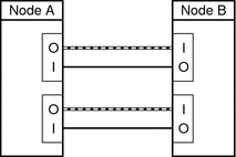
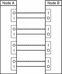
Configuration With Point-to-Point Connections:
A two-node cluster can use a point-to-point connection, requiring no transport junction.
-
Connect the ends of the cables that are marked SCI Out to the I connectors on the adapters.
-
Connect the ends of the cables that are marked SCI In to the O connectors of the adapters as shown in the previous diagram.
See the following diagrams for cabling details.
-
-
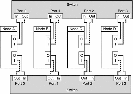
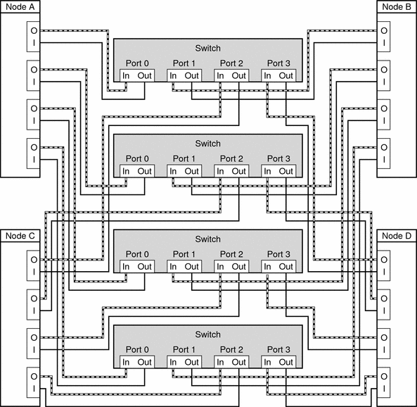
Configuration With Transport Junction:
A three-node or four-node cluster requires SCI transport junctions.
-
Set the Unit selectors on the fronts of the SCI transport junctions to F. Do not use the X-Ports on the SCI transport junctions.
-
Connect the ends of the cables that are marked SCI Out to the I connectors on the adapters and the Out connectors on the transport junctions.
-
Connect the ends of the cables that are marked SCI In to the O connectors of the adapters and In connectors on the transport junctions, as shown in the previous diagram.
See the following diagrams for cabling details. For the procedure about how to install and cable, see the SCI switch documentation that shipped with your hardware switches.
-
Figure 3–3 Configuration With Point-to-Point Connections: Two Interconnects

Figure 3–4 Configuration With Point-to-Point Connections: Four Interconnects

Figure 3–5 Configuration With Transport Junction: Two Interconnects

Figure 3–6 Configuration With Transport Junction: Four Interconnects

-
Troubleshooting
If you have problems with your PCI-SCI interconnect, perform the following tasks:
-
Verify that the LED on the PCI-SCI transport adapter is blinking green rapidly. For detailed LED interpretations and actions, see the documentation that shipped with your host adapter.
-
Verify that the PCI-SCI transport adapter card's DIP switch settings are correct. For more information, see the documentation that shipped with your PCI-SCI host adapter.
-
Verify that the PCI-SCI cables are correctly connected. The PCI-SCI cable connects to the connector that is marked SCI In on the PCI-SCI adapter cards. If you are using transport junctions, the PCI-SCI cable also connects to the Out ports on the SCI transport junctions.
-
Verify that the PCI-SCI cables are correctly connected. The PCI-SCI cable connects to the connector that is marked SCI Out on the PCI-SCI adapter cards. If you are using transport junctions, the PCI-SCI cable also connects to the In ports on the SCI transport junctions.
-
Verify that the PCI-SCI switch unit selectors are set to F.
See Also
-
To increase Oracle Real Application Clusters performance, set the max-vc-number parameter in the /etc/system file for each node. Choose the value that corresponds to the number of interconnects in your configuration:
-
(2 PCI-SCI interconnects) max-vc-number = 32768
-
(3 PCI-SCI interconnects) max-vc-number = 49152
-
(4 PCI-SCI interconnects) max-vc-number = 65536
-
-
To install the Sun Cluster software and configure the Sun Cluster software with the new interconnect, see Chapter 2, Installing and Configuring Sun Cluster Software, in Sun Cluster Software Installation Guide for Solaris OS.
- © 2010, Oracle Corporation and/or its affiliates
