Appendix A Cabling Diagrams
Sun StorEdge A1000 and Netra st A1000 Cabling Diagrams
Installing a Sun StorEdge A1000 or Netra st A1000 Storage Array
The storage arrays must be configured in pairs for the Sun Cluster environment.
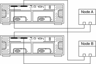
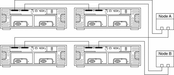
To cable the storage arrays, connect the differential SCSI cable between the node and the storage array. Ensure that the entire SCSI bus length in each SCSI chain is less than 25 m. This measurement includes the cables to both nodes, as well as the bus length that is internal to each storage array, node, and host adapter. Figure A–1 and Figure A–2 illustrate a storage array that is cabled in a Sun Cluster environment.
Figure A–1 Installing a Storage Array With One Pair

Figure A–2 illustrates how to cable the storage array in a daisy-chain configuration. If you place two storage arrays on a SCSI chain, ensure that each storage array's ID dial is set to a unique number.
Figure A–2 Storage Array With Two Pairs and Daisy Chaining

Sun StorEdge A3500 Cabling Diagrams
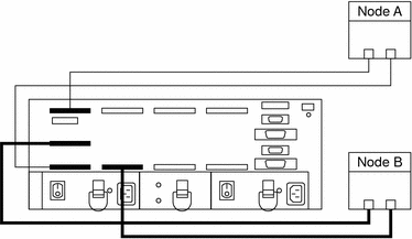
Installing a Sun StorEdge A3500 Storage System
Figure A–3 Installing a StorEdge A3500 Storage System: An Example

For more sample configurations, see the Sun StorEdge A3500/A3500FC Hardware Configuration Guide.
For the procedure about how to install the cables, see the Sun StorEdge A3500/A3500FC Controller Module Guide.
Adding a Sun StorEdge A3500 Storage System
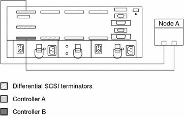
Connect the differential SCSI cable between the node and the controller module, as shown in Figure A–4. Ensure that the entire SCSI bus length to each storage array is less than 25 m. This measurement includes the cables to both nodes, as well as the bus length that is internal to each storage array, node, and host adapter.
Figure A–4 Cabling a StorEdge A3500 Storage System: An Example, Part 1

Figure A–5 Cabling a StorEdge A3500 Storage System: An Example, Part 2

- © 2010, Oracle Corporation and/or its affiliates
