| C H A P T E R 2 |
|
Installing the Server |
This chapter provides instructions for installing the server in an equipment rack.
|
Note - If your rackmount kit came with its own instructions, use the instructions in your rackmount kit instead of the instructions in this chapter. After performing the server installation, proceed to Chapter 3 for first-time power on. |
This chapter contains the following sections:
|
Note - References to left and right are from your viewpoint as you face either the front or rear of the equipment. |
|
Note - Ensure that you have all of the parts in the rackmount kit before you begin the installation of the server. See Shipping Kit Inventory List. |
The rackmount kit contains two slide rail assemblies. A slide rail assembly can be installed on either the right or left side of the rack.
A slide rail assembly consists of two parts: a slide rail and a removeable mounting bracket. The slide rail attaches to the rack posts. The mounting bracket attaches to the server chassis.
|
1. Pull both mounting brackets completely out of their respective slide rails:
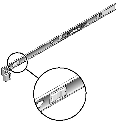
a. Simultaneously press and hold the upper and lower lock buttons of the slide rail lock (FIGURE 2-1).
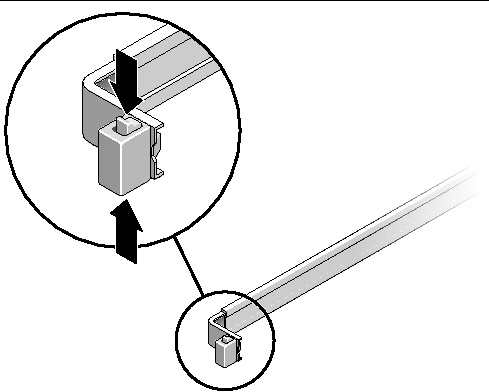
b. Pull the mounting bracket out until it locks in the extended position.
c. Slide the mounting bracket release button in the direction shown in FIGURE 2-2, then slide the mounting bracket out of the slide rail.
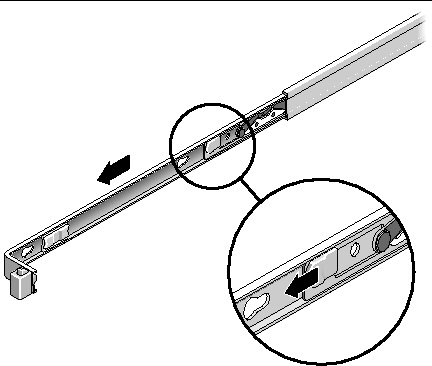
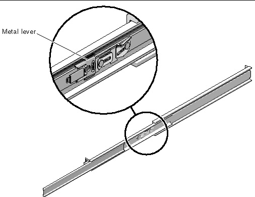
d. Press the metal lever (labeled Push) on the middle section (FIGURE 2-3) of the sliding rail, then push the middle section back into the rack.
2. Attach a mounting bracket to the right side of the chassis.
a. Position the mounting bracket against the chassis (FIGURE 2-4) so that the slide rail lock is at the front and the three keyed openings on the mounting bracket are aligned with the three locating pins on the side of the chassis.
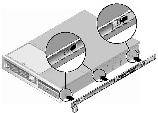
b. With the heads of the three locating pins protruding though the three keyed openings in the mounting bracket, pull the mounting bracket toward the front of the chassis until the bracket locks into place with an audible click.
c. Verify that all three locating pins are trapped in the keyed openings and that the rear locating pin has engaged the mounting bracket lock, as shown in the right side of FIGURE 2-4.
3. Attach the second mounting bracket to the left side of the chassis.
4. Determine which rack hole numbers to use when attaching the slide rails to the rack posts.
The server is two rack units tall (2 RU). The slide rails will occupy the lower half of the 2 RU space.
5. Determine which screws you will use to mount the slide rails.
If your rack has threaded mounting holes in the rack posts, determine whether the threads are metric or standard. Select the appropriate screws from the package included in the mounting kit.
If your rack does not have threaded mounting holes, the mounting screws are secured with a caged nut.
6. Attach a slide rail to the right front rack post.
a. Loosely attach the front of a slide rail to the right front rack post (FIGURE 2-5) using two screws.
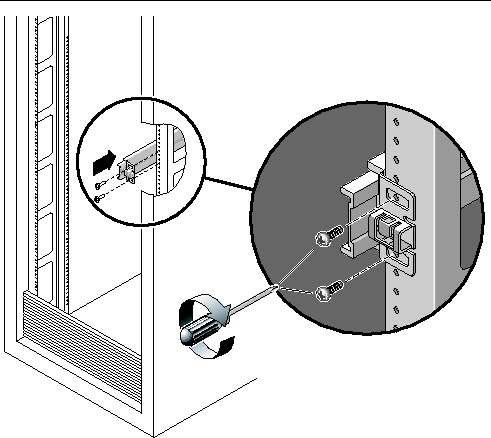
b. Adjust the length of the slide rail by sliding the rear mounting flange to reach the outside edge of the rear rack post.
c. Loosely attach the rear of the slide rail to the rear rack post with two screws.
7. Attach the second slide rail to the left rack posts in a similar manner. Again, do not tighten the screws.
8. Use the slide rail spacing tool to adjust the distance between the slide rails:
a. At the front of the rack, plug the left side of the tool into slots at the end of the left rail (FIGURE 2-6).
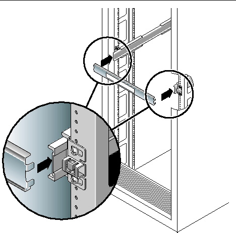
b. Insert the right side of the tool into the front end of the right rail, while sliding the end of the rail to the right or left as needed to allow the the ends of the tool to enter the ends of both rails.
The distance between the rails is now equal to the width of the server with mounting brackets.
c. Tighten the screws to lock the ends of the rails in place.
d. At the rear of the rack, repeat Step a through Step c. for the rear ends of the rails.
9. Deploy the anti-tilt bar, if the chassis or rack is so equipped.

|
Caution - The weight of the server on extended slide rails can be enough to overturn an equipment rack. |

|
Caution - The server weighs approximately 40 lb (18 kg). Two people are required to lift and mount the system into a rack enclosure when using the procedures in this chapter. |
10. Insert the ends of the mounting brackets into the sliding rails (FIGURE 2-7).
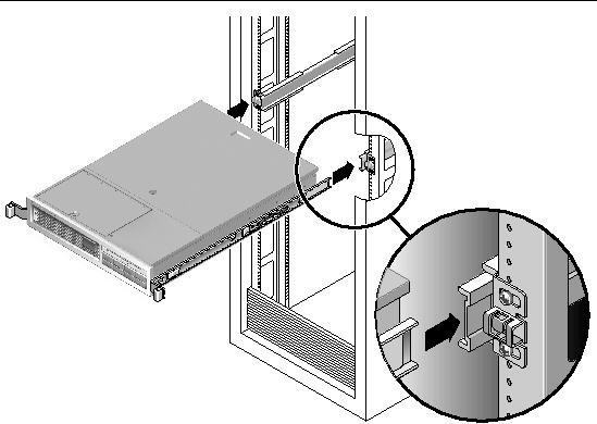
11. Slide the chassis into the rack.

|
Caution - Verify that the server is securely mounted in the rack, and that the slide rails are locked to the mounting brackets, before continuing. |
|
The cable management assembly (CMA) clips into the ends of the left and right sliding rail assemblies. No screws are necessary for mounting the CMA.

|
Caution - Support the CMA during this installation. Do not allow the assembly to hang by its own weight until it is secured by all three attachment points. |
1. At the rear of the rack, plug the CMA rail extension into the end of the left sliding rail assembly (FIGURE 2-8). The tab at the front of the rail extension will click into place.
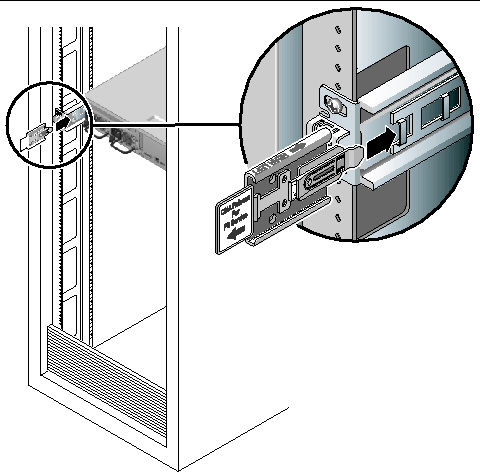
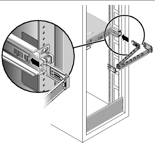
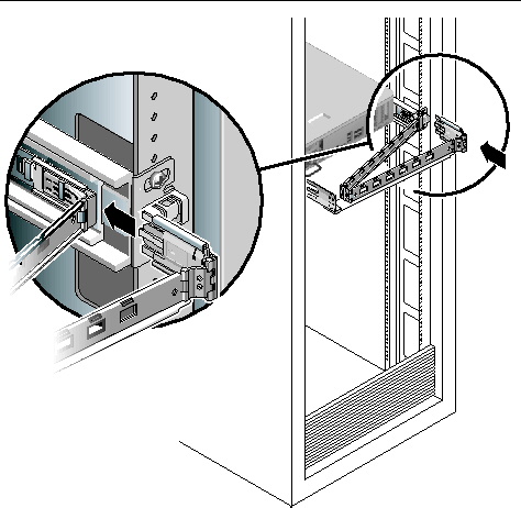
The right sides of the two CMA arms have hinged extensions. On the manufacturer's instruction sheet, the smaller extension is called the CMA Connector for Inner Member. It attaches to the right mounting bracket. The larger extension is called the CMA Connector for Outer Member, and attaches to the right sliding rail.
2. Insert the smaller extension into the clip located at the end of the mounting bracket (FIGURE 2-9).
3. Insert the larger extension into the end of the right sliding rail (FIGURE 2-10).
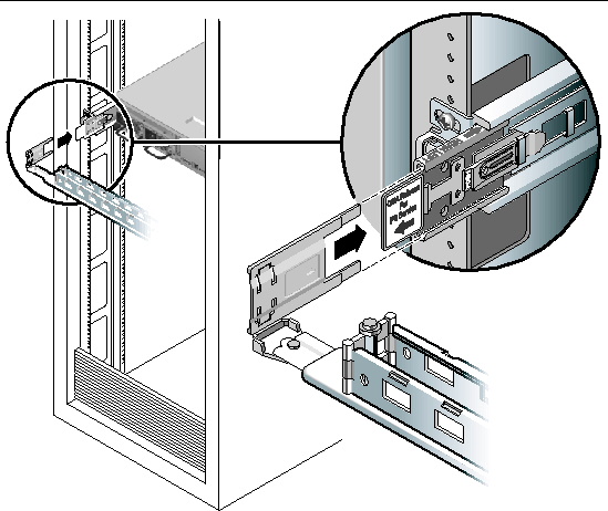
4. Insert the hinged plastic connector at the left side of the CMA fully into the CMA rail extension (FIGURE 2-11).
The plastic tab on the CMA rail extension locks the hinged plastic connector in place.
|
|
Tip - Two people are needed this procedure: one to move the server in and out of the rack and one to observe the cables and CMA. |
1. For a free-standing rack, deploy the anti-tilt bar.
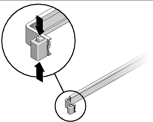
2. Unlock the slide lock buttons (FIGURE 2-12) at the right and lefts sides of the chassis, and slowly pull the server out of the rack until the slide rails reach their stops.
3. Inspect any attached cables for binding or kinks.
4. Verify that the CMA extends fully and does not bind in the slide rails.
5. Verify that the server extends fully and locks in the maintenence position.
The server should stop after approximately 15 inches (40 cm) of travel.
6. Pull both slide rail release buttons toward you simultaneously and slide the server back into the rack (FIGURE 2-13).
The server should slide smoothly into the rack without binding.
7. Verify that the CMA retracted without binding.
8. Adjust the cable hangers and CMA as required.
See Managing Cables With the CMA.
If it becomes necessary to remove the server from the rack, or to open the server case for maintenance or hardware upgrades, refer to the Sun SPARC Enterprise T2000 Server Service Manual for procedures.
In addition, the SPARC Enterprise T2000 server has serial and USB ports available for connections to optional devices.
|
Note - When you are finished connecting the cables to the server, ensure that the server can slide smoothly in and out of the rack without binding or damaging the cables. See the section, To Verify the Operation of the Slide Rails and the CMA. |
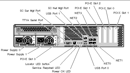
Use FIGURE 2-14 to locate the connectors and power supplies on the back of the server.
USB ports 2 and 3 are located on the front panel (FIGURE 2-15).

|
The server has four RJ-45 Gigabit Ethernet network connectors. They are marked NET0, NET1, NET2, and NET3 (FIGURE 2-16).
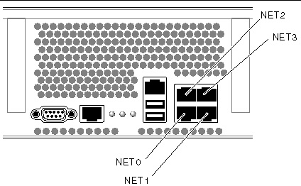
1. Connect a Category 5 cable from your network switch or hub to Ethernet Port 0 (NET0) on the rear of the chassis.
2. As needed, connect Category 5 cables from your network switch or hub to the remaining Ethernet ports (NET1, NET2, NET3).
|
The SC serial management port is marked SER MGT. It is the leftmost RJ-45 port on the rear of the chassis (FIGURE 2-17).
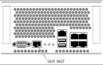
Use this port for server management. This port is needed to set up the SC network management port, as detailed in Enabling the System Controller Network Management Port.
|
Note - Use the SC serial management port only for server management. It is the default connection between the system controller and a terminal or a computer. |

|
 Connect a Category 5 cable from the SC serial management port to the terminal device.
When connecting either a DB-9 or a DB-25 cable, use an adapter to perform the crossovers given for each connector.
|
The SC network management port is marked NET MGT. It is the RJ-45 port above the rear USB ports.
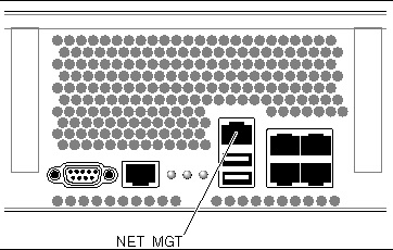
 Connect a Category 5 cable from your network switch or hub to the Network Management Port.
|
Note - This port is not operational until you configure the network settings (through the serial managment port), as detailed in To Configure the System Controller Network Management Port. |
|
Note - The SC network management port is configured by default to retrieve network settings via Dynamic Host Configuration Protocol (DHCP) and allow connections using Solaris Secure Shell (SSH®). You might need to modify these settings for your network. Instructions are given in Chapter 3. |
|
Note - Finish the hardware procedures in this chapter, but do not attach the AC power cables yet. |
Powering on the system for the first time requires special preparation and procedures. For example, if you have not prepared a display before connecting the AC power cables, system messages may be lost. You will be instructed to connect the server to AC power in Powering On the System for the First Time.

|
Caution - The server goes into standby mode and the system controller initializes as soon as the AC power cables are connected to the power source. |
The TTYA serial port connector uses a DB-9 connector (item 1 in FIGURE 2-19). Use this port for general purpose serial data transfers. This port is not connected to the SC serial management port.
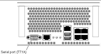
Use a null modem cable or an adapter to perform the crossovers given for each connector.
Four Universal Serial Bus (USB) ports are provided on the server. USB ports 0 and 1 are located on the rear of the chassis (FIGURE 2-14). Ports 2 and 3 on the front of the chassis (FIGURE 2-15).
|
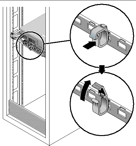
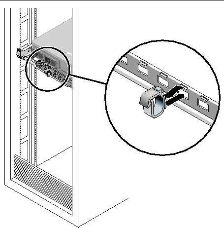
1. To open a cable clip, press the front of the cable clip and lift the hinged top.
2. Route cables through the clip, then press the top of the cable clip to lock.
|
1. To remove a cable clip from the CMA arm, lift the cable clip approximately 3/8 in (10 mm) to free the lower clip lock, then rotate the entire clip about 90 degrees to free the upper clip lock.
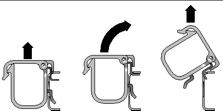
2. To insert a cable clip, position the upper and lower clip locks in the slots of the CMA arm, then press the clip down approximately 3/8 in (10 mm).
Copyright © 2007, Sun Microsystems, Inc. All Rights Reserved.