| C H A P T E R 2 |
|
Replacing Hot-Pluggable and Hot-Swappable CRUs |
This chapter describes how to replace the hot-swappable and hot-pluggable customer replaceable units (CRUs) in the Sun Fire V215 and V245 servers.
The following topics are covered:
Hot-pluggable devices are those devices that you can remove and install while the server is running, but you must perform administrative tasks before or after installing the hardware (for example, mounting a hard drive). In the Sun Fire V215 and V245 servers, the following device is hot-pluggable:
Hot-swappable devices are those devices that can be removed and installed while the server is running without affecting the rest of the server’s capabilities. In the Sun Fire V215 and V245 servers the following devices are hot-swappable:
| Note - In Sun Fire V215 and V245 servers, the chassis-mounted hard drives can be hot-swappable (depending on how they are configured). |
The hard drives in the Sun Fire V215 and V245 servers are hot-pluggable, but this capability depends on how the hard drives are configured. To hot-plug a drive you must take the drive offline (to prevent any applications from accessing it, and to remove the logical software links to it) before you can safely remove it.
The following situations inhibit your ability to hot-plug a drive:
If your drive falls into one of these conditions, you must shut the server down before you replace the hard drive. See Section 3.2.2, Powering Off the Server - ALOM Command Line or Section 3.2.3, Powering Off the Server - Graceful Shutdown or Section 3.2.4, Powering Off the Server - Emergency Shutdown.
Removing a hard drive from the Sun Fire V215 and V245 servers is a three step process. You must first identify the drive you want to remove, unconfigure that drive from the server, and then manually remove the drive from the chassis.
Perform the following process to remove a hard drive:
1. At the Solaris prompt, type the cfgadm -al command to list all drives in the device tree, including drives that are not configured. Type:
This command should identify the Ap_id for the hard drive you want to remove. For example, the output should look like:
2. Type the cfgadm -c unconfigure command to unconfigure the disk. For example, type:
where c0:dsk/c0t1d1 is the disk that you are trying to unconfigure.
3. Wait until the blue Service Action Allowed indicator lights (FIGURE 2-1).
This indicator helps you to identify which drive is unconfigured and can be removed.
FIGURE 2-1 Locating the Hard Drive Release Button and Latch
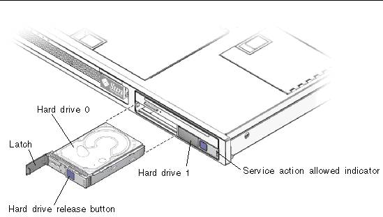
4. On the drive you plan to remove, push the hard drive release button (FIGURE 2-1).

|
Caution - The latch is not an ejector. Do not bend the latch too far to the left. Doing so can damage the latch. |
5. Grasp the latch and pull the drive out of the drive slot.
Installing a hard drive into the Sun Fire V215 and V245 servers is a two-step process. You must first install a hard drive into the drive slot that you want to install the drive in, and then you must configure that drive to the server.
Perform the following process to install a hard drive.
1. If necessary, remove the blank panel from the chassis.
2. Align the replacement drive to the drive slot (FIGURE 2-1).
Hard drives are physically addressed according to the slot in which they are installed. If you removed an existing hard drive from a slot in the server, you must install the replacement drive in the same slot as the drive that was removed.
3. Slide the drive into the drive slot until it is fully seated.
4. Close the latch to lock the drive in place.
5. At the Solaris prompt, issue the cfgadm -al command to list all drives in the device tree, including any drives that are not configured. Type:
This command should help you identify the Ap_id for the hard drive you installed. For example, the output should look like:
6. Issue the cfgadm -c configure command to configure the disk. For example, type:
where c0::sd1 is the disk that you are trying to configure.
7. Wait until the blue Service Action Allowed indicator is extinguished on the drive that you installed (FIGURE 2-1).
8. At the Solaris prompt, issue the cfgadm -al command to list all drives in the device tree, including any drives that are not configured. Type:
This command should identify the Ap_id for the hard drive that you installed. The drive you installed should be is configured. For example, the output should look like:
9. Issue the iostat -E command. Type:
The iostat -E command displays information about your system’s installed devices such as manufacturer, model number, serial number, size, and system error statistics.
Six hot-swappable fans trays are located under the front cover door.
Two working fan trays are required to provide adequate cooling for the Sun Fire V215 and V245 servers. If a fan tray fails, replace it as soon as possible to maximize server availability.
The following indicators are lit when a fan tray fault is detected:
If an overtemperature conditions occurs, the front panel CPU Overtemperature indicator lights and a message is displayed on the console and logged by ALOM.
| Tip - You can use the showfault command at the sc> prompt to view the current faults. |
1. Gain access to the top of the server where the front cover door for the fan tray is located (FIGURE 2-2).
You might need to extend the server to a maintenance position. See Section 3.2.5, Extending the Server to the Maintenance Position - Rackmounted Servers Only.
FIGURE 2-2 Removing a Fan Tray
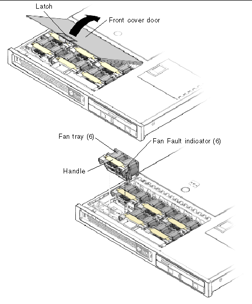
2. Lift the latch, and open the front cover door.
3. Identify the faulty fan tray.
A lit Fan Fault indicator on the top of a fan tray indicates that the fan tray is faulty.
| Note - Sun Fire V215 servers have 2 fans installed in each fan tray. |
4. Pull up on the fan tray handle until the fan tray is removed from the chassis.
1. With the front cover door open, install the replacement fan tray into the server (FIGURE 2-2).
2. Apply firm pressure to fully seat the fan tray.
3. Verify that the Fan Fault indicator on the replaced fan tray is not lit. Also verify that the Top Fan indicator, Service Required indicators, and the Locator indicator/Locator button are not lit (FIGURE 2-2), (FIGURE 2-3) and (FIGURE 2-4).
FIGURE 2-3 Top Fan, System Required Indicator, Locator Indicators, and Locator Button

FIGURE 2-4 Failure and Service Required Indicators

| Note - Each power supply has a failure indicator. |
4. Close the front cover door.
5. If necessary, return the server to its normal position in the rack.
A single hot-swappable fan tray is located under the rear fan tray cover door (Sun Fire V245 server).
| Note - This hot-swappable fan tray is located under the front fan tray cover door on the Sun Fire V215 server. |
If the fan tray fails, replace it as soon as possible to maximize server availability.
1. Gain access to the top of the server where the rear cover door for the fan tray is located (FIGURE 2-5).
The hot-swappable fan tray for the Sun Fire V215 server is located under the front fan tray cover door.
| Note - You might need to extend the server to a maintenance position. See Section 3.2.5, Extending the Server to the Maintenance Position - Rackmounted Servers Only. |
2. Lift the latch, and open the rear cover door.
3. Verify that the fan tray is faulty.
A lit Fan Fault indicator on the top of a fan tray indicates that the fan tray is faulty.
| Note - The hard drive fan tray has two fans. |
4. Pull up on the fan tray handle and remove the fan tray from the chassis.
FIGURE 2-5 Hard Drive Fan Tray - Sun Fire V245 Server
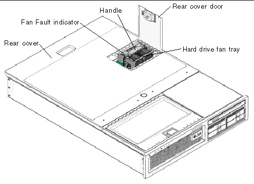
1. With the rear cover door open, install the replacement fan tray into the server (FIGURE 2-5).
The hot-swappable fan tray for the Sun Fire V215 server is located under the front fan tray cover door.
2. Apply firm pressure to fully seat the fan tray.
3. Verify that the Fan Fault indicator on the replaced fan tray is not lit.
The Sun Fire V245 server’s standard redundant hot-swappable power supplies enable you to remove and replace a power supply without shutting the server down, provided that the other power supply is online and working.
| Note - An optional redundant, hot-swappable power supply is available for the Sun Fire V215 server. |
The following indicators are lit when a power supply fault is detected:
If a power supply fails and you do not have a replacement available, leave the failed power supply installed to ensure proper air flow in the server.
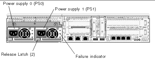
1. Identify which power supply (0 or 1) requires replacement (FIGURE 2-6).
A lit (amber) failure indicator on a power supply indicates that a failure was detected.
| Tip - Additional information about power supply status can be found the Sun Fire V215 and V245 Getting Started Guide (819-3041). |
FIGURE 2-6 Location of the Power Supplies and Release Latches
2. Gain access to the rear of the server where the faulty power supply is located.
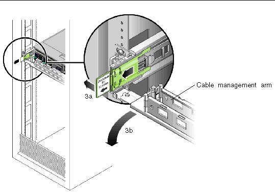
3. Release the cable management arm (CMA) (FIGURE 2-7).
The CMA is located at the rear of the server rack.
b. Rotate the cable management arm out of the way so that you can access the power supply.
4. Disconnect the power cord from the faulty power supply.
5. Grasp the power supply handle and move the power supply latch to the right.
6. Pull the power supply out of the chassis.
FIGURE 2-7 Rotating the Cable Management Arm to Access the Server Power Supplies
1. Align the replacement power supply with the empty power supply chassis bay.
2. Slide the power supply into the bay until it is fully seated.
3. Reconnect the power cord to the power supply.
4. Close the CMA, inserting the end of the CMA into the rear left rail bracket (FIGURE 2-7).
5. Verify that the Failure indicator on the replaced power supply (FIGURE 2-4), the Service Required (FIGURE 2-3) indicator, and the front and rear Service Required indicators are not lit (FIGURE 2-3) and (FIGURE 2-4).
6. At the sc> prompt, type the showenvironment command to verify the status of the power supplies.
Copyright © 2008, Sun Microsystems, Inc. All Rights Reserved.