| C H A P T E R 3 |
|
Replacing Cold-Swappable FRUs |
This chapter describes how to replace cold-swappable, field-replaceable units (FRUs) in the Sun Fire V215 and V245 servers.
The following topics are covered:
For a list of CRUs and FRUs, see Section B.1, Customer and Field-Replaceable Units.

|
Caution - Never attempt to run the server with the covers removed. Hazardous voltage present. |

|
Caution - Equipment damage possible. The covers must be in place for proper air flow. |
This section describes important safety information that you need to know prior to removing or installing parts in the Sun Fire V215 and V245 servers.
For your protection, observe the following safety precautions when setting up your equipment:
The following symbols might appear in this document, note their meanings:

|
Caution - There is a risk of personal injury and or equipment damage. To avoid personal injury and equipment damage, follow the instructions. |

|
Caution - Hot surface. Avoid contact. Surfaces are hot and might cause personal injury if touched. |

|
Caution - Hazardous voltages are present. To reduce the risk of electric shock and danger to personal health, follow the instructions. |
Electrostatic discharge (ESD) sensitive devices, such as the motherboards, PCI cards, hard drives, and memory cards require special handling.
Wear an antistatic wrist strap and use an antistatic mat when handling components such as hard drive assemblies, circuit boards, or PCI cards. When servicing or removing server components, attach an antistatic strap to your wrist and then to a metal area on the chassis. Following this practice equalizes the electrical potentials between you and the server.
| Note - An antistatic wrist strap is no longer included in the accessory kit for the Sun Fire V215 and V245 servers. However, antistatic wrist straps are still included with optional components. |
Place ESD-sensitive components such as motherboards, memory, and other PCBs on an antistatic mat.
Before replacing parts that are not hot-swappable or hot-pluggable inside the Sun Fire V215 and V245 servers, perform the following procedures:
| Note - These procedures do not apply to the hot-swappable and hot-pluggable devices (fans, power supplies, and hard drives) described in Chapter 2. |
The procedures that you perform after removing, installing, or repairing the servers are described in Section 3.4, Procedures for Finishing Up.
The Sun Fire V215 and V245 servers can be serviced with the following tools:
| Note - Additional information about powering on the server is located in the Sun Fire V215 and V245 Servers Administration Guide (819-3036). |
You can use ALOM to perform a graceful shutdown of the server, to ensure that all of your data is saved, and to ensure that the server is ready for restart.
1. Login as superuser or equivalent.
Depending on the type of problem, you might want to view server status, log files, or run diagnostics before you shut down the server. Refer to the Sun Fire V215 and V245 Server Administration Guide (819-3036) for log file information.
Refer to your Solaris system administration documentation for additional information.
3. Save any open files and quit all running programs.
Refer to your application documentation for specific information on these processes.
Refer to the Solaris system administration documentation for additional information.
5. Switch from the system console to the ALOM sc> prompt by typing the #. (Hash Period) key sequence.
6. At the ALOM sc> prompt, issue the poweroff -fy command.
| Note - You can also use the Power button on the front of the server to initiate a graceful server shutdown (See Section 3.2.3, Powering Off the Server - Graceful Shutdown). This button is recessed to prevent accidental server power-off. Use the tip of a pen to operate this button. |
Refer to the Sun Advanced Lights Out Management (ALOM) Administration Guide for more information about the ALOM poweroff command.
 Press and release the Power button.
If necessary, use a pen or pencil to press the Power button.

|
Caution - All applications and files will be closed abruptly without saving changes. File system corruption might occur. |
 Press and hold the Power button for 4 seconds.
If the server is installed in a rack with extendable slide rails, use this procedure to extend the server to the maintenance position.
1. (Optional) Issue the following command from the ALOM sc> prompt to locate the system that requires maintenance (FIGURE 3-1).
Once you have located the server, press the Locator indicator/Locator button to turn it off.
FIGURE 3-1 Locator Indicator/Locator Button

2. Verify that no cables will be damaged or interfere when the server is extended.
Although the cable management arm (CMA) that is supplied with the server is hinged to accommodate extending the server, you should ensure that all cables and cords are capable of extending.
3. From the front of the server, release the two slide release latches (FIGURE 3-2).
Squeeze the green slide release latches to release the slide rails.
FIGURE 3-2 Slide Release Latches
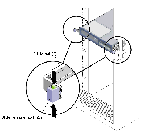
4. While squeezing the slide release latches, slowly pull the server forward until the slide rails latch.

|
Caution - If necessary, use two people to dismount and carry the chassis. |
1. Disconnect all the cables and power cords from the server.
2. Extend the server to the maintenance position.
See Section 3.2.5, Extending the Server to the Maintenance Position - Rackmounted Servers Only.
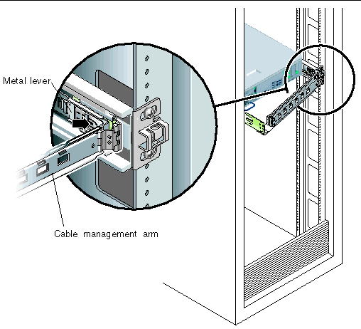
3. Press the metal lever that is located on the inner side of the rail to disconnect the cable management arm (CMA) from the rail assembly (FIGURE 3-3).
The CMA is still attached to the cabinet, but the server chassis is now disconnected from the CMA.
FIGURE 3-3 Metal Lever and Cable Management Arm

|
Caution - If necessary, use two people to dismount and carry the chassis. |
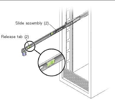
4. From the front of the server, pull the release tabs forward and pull the server forward until it is free of the rack rails (FIGURE 3-4).
A release tab is located on each rail.
FIGURE 3-4 Release Tabs and Slide Assembly
5. Set the server on a sturdy work surface.
1. Prepare an antistatic surface to set parts on during the removal, installation, or replacement process.
Place ESD-sensitive components such as the printed circuit boards on an antistatic mat. The following items can be used as an antistatic mat:
2. Attach an antistatic wrist strap.
When servicing or removing server components, attach an antistatic strap to your wrist and then to a metal area on the chassis.

|
Caution - The system supplies standby power to the circuit boards even when the server is powered off. |
 Disconnect the power cords from the power supplies.
| Note - Some field-replaceable units (FRUs) require removal of the rear cover. |
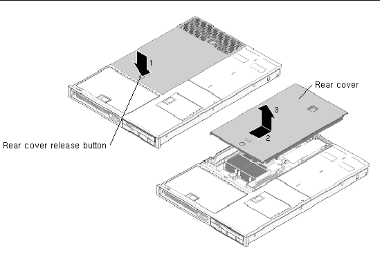
1. Press and hold the rear cover release button (FIGURE 3-5).
2. Slide the rear cover toward the rear of the server.
Slide the rear cover to the rear about a 0.5 inch (12.7 mm).
| Note - If the rear cover is removed before the server is powered down, the Sun Fire V215 server will go into Standby mode. |
FIGURE 3-5 Removing the Rear Cover
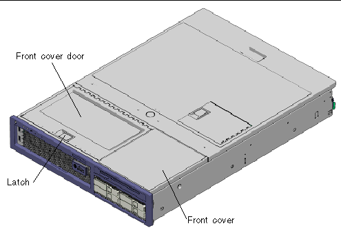
1. Open front cover door (FIGURE 3-6).
Lift the latch and open the front cover door.
FIGURE 3-6 Front Cover, Front Cover Door, and Latch - Sun Fire V245
2. Loosen the captive screw (FIGURE 3-7).
Use a screwdriver to loosen the captive screw. The captive screw secures the bezel to the server.
FIGURE 3-7 Removing the Bezel From the Server - Sun Fire V245
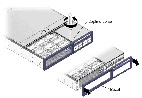
3. Remove the bezel from the chassis.
The bezel is held in place by a mounting tab and fasteners that secure the bezel to the chassis.
| Note - Some field-replaceable units (FRUs) require the removal of the front cover. |
See Section 3.2.9, Removing the Rear Cover.
2. Open the front cover door (FIGURE 3-6).
See Section 3.2.10, Removing the Bezel.
4. Remove the front cover (FIGURE 3-6).
While holding the front cover door open, slide the front cover forward and remove.

|
Caution - To prevent the system from overheating, ensure that the air baffle is correctly installed before powering on the server. |
1. Perform the procedures described in Section 3.2, Procedures for Parts Replacement.
See Section 2.2.7, “Removing the Rear Cover” on page 2-9.
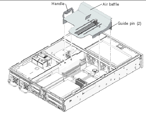
3. Lift the handle and remove the air baffle from the server (FIGURE 3-8).
FIGURE 3-8 Air Baffle, Guide Pins, and Handle - Sun Fire V245

|
Caution - When the server is in operation, ensure that the air baffle is correctly installed to prevent the system from overheating. |
1. Use the guide pins to align and install the air baffle into the chassis (FIGURE 3-8).
Ensure that the air baffle is aligned and fully seated in the chassis.
2. Perform the procedures described in Section 3.4, Procedures for Finishing Up.
This section provides procedures for replacing the following field replaceable units (FRUs) inside the server chassis:
To locate these FRUs, see Section B.1, Customer and Field-Replaceable Units.
| Note - Procedures for removing and installing hot-swappable and hot-pluggable CRUs are described in Chapter 2. |
1. Perform the procedures described in Section 3.2, Procedures for Parts Replacement.
See Section 3.2.9, Removing the Rear Cover.
3. (Sun Fire V245) Remove the air baffle.
Removal of a long PCI card might require you to remove the air baffle.
4. Locate the PCI card that you want to remove.
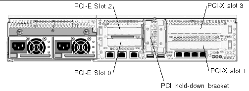
To locate the PCI card slots, refer to FIGURE 3-9 and FIGURE 3-10.
FIGURE 3-9 Location of PCI-E and PCI-X Slots, and PCI Hold-Down Bracket - Sun Fire V215

FIGURE 3-10 Location of PCI-E and PCI-X Slots, and PCI Hold-Down Bracket - Sun Fire V245
5. If necessary, make a note of where the PCI card is installed.
Also note the location of any cables for reinstallation later.
6. Release the PCI hold-down bracket (FIGURE 3-9) or (FIGURE 3-10).
Rotate the PCI hold-down bracket 90 degrees so it no longer covers the PCI card that you want to remove.
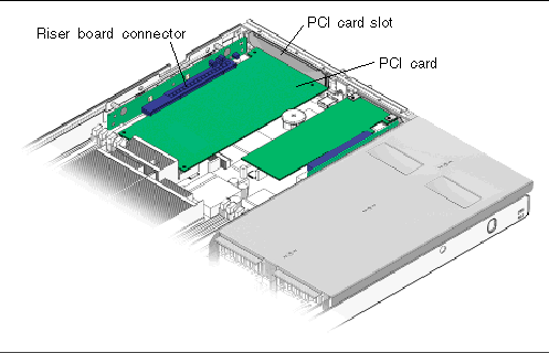
7. Carefully remove the PCI card from the PCI card slot and riser board connector (FIGURE 3-11).
FIGURE 3-11 Riser Board and PCI Card Connector - Sun Fire V215
8. Place the PCI card on an antistatic mat.
1. Unpackage the replacement PCI-E or PCI-X card, and place it on an antistatic mat.
2. Locate the proper PCI slot for the card you are replacing (FIGURE 3-9 or FIGURE 3-10).
3. If necessary, review the PCI-E and PCI-X card guidelines to plan your installation.
See Section A.2, PCI-E and PCI-X Card Guidelines for additional information.
4. Rotate the PCI hold-down bracket 90 degrees so you can install the card.
5. If necessary, remove the filler panel.
6. Insert the PCI card into the slot.
7. Rotate the PCI hold-down bracket 90 degrees to lock the card in place.
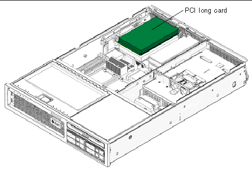
8. (Sun Fire V245) If a PCI long card is installed, use the brace from the air baffle to support the card.
FIGURE 3-12 Installing a PCI Long Card - Sun Fire V245
9. Perform the procedures described in Section 3.4, Procedures for Finishing Up.
1. Perform the procedure described in Section 3.2, Procedures for Parts Replacement.
See Section 3.2.9, Removing the Rear Cover.
3. (Sun Fire V245) Remove the air baffle.
See Section 3.2.12, (Sun Fire V245) Removing the Air Baffle.
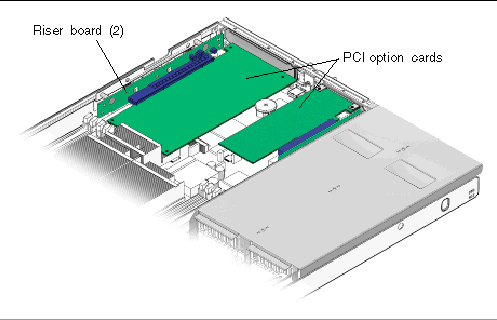
4. Remove any PCI option cards that are installed (FIGURE 3-13).
FIGURE 3-13 Riser Boards and PCI Option Cards - Sun Fire V215
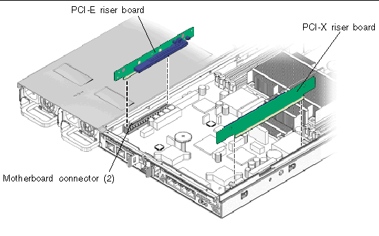
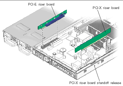
5. Remove the PCI-X and PCI-E riser boards (FIGURE 3-14).
If necessary, remove the screws that secure the riser board to the chassis.
FIGURE 3-14 PCI-E and PCI-X Riser Boards
6. Place the PCI riser boards on an antistatic mat.
1. Unpackage the replacement PCI-E or PCI-X card, and place it on an antistatic mat.
2. Install the PCI-E and PCI-X riser boards in the motherboard connectors (FIGURE 3-14).
If necessary, install the screws that secure the riser board to the chassis.
3. Install the PCI option cards.
See Section 3.3.2, Installing PCI-E or PCI-X Cards.
4. (Sun Fire V245) If a PCI long card is installed, use the brace from the air baffle to support the card.
5. Perform the procedures described in Section 3.4, Procedures for Finishing Up.

|
Caution - This procedure requires that you handle components that are sensitive to static discharge. This sensitivity can cause the component to fail. To avoid this problem, ensure that you follow antistatic practices as described in Section 3.2.7, Performing Electrostatic Discharge - Antistatic Prevention Measures. |

|
Caution - Ensure that all power is removed from the server before removing or installing DIMMs. |
1. Perform the procedures described in Section 3.2, Procedures for Parts Replacement.
Section 3.2.9, Removing the Rear Cover.
3. Remove any PCI-X or PCI-E cards.
See Section 3.3.1, Removing PCI-E and PCI-X Cards.
4. (Sun Fire V245) Remove the air baffle (FIGURE 3-8).
See Section 3.2.12, (Sun Fire V245) Removing the Air Baffle.
5. (Sun Fire V215) Remove the motherboard to front I/O board cable (FIGURE 3-20).
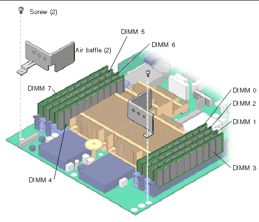
6. Locate the DIMMs that you want to replace (See FIGURE 3-15 and TABLE 3-1).
| Tip - If you are removing DIMMs as a result of a system error or fault, refer to TABLE 3-1 for additional information. |
| Tip - Make a note of the DIMM location so that you can install the replacement DIMM in the same location. |
| Note - For memory configuration information see Section A.1, DIMM Guidelines. |
7. (Sun Fire V215) Remove the screws and air baffles for the DIMMs you want to remove (FIGURE 3-15).
To obtain adequate clearance, it might be necessary to remove the front cover, see Section 3.2.11, Removing the Front Cover.
FIGURE 3-15 Removing the Air Baffle - Sun Fire V215
8. Push down on the ejector tabs on each side of the DIMM until the DIMM is released (FIGURE 3-16).
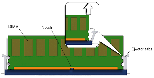
9. Grasp the top corners of the faulty DIMM and remove it from the server.
10. Place the DIMM on an antistatic mat.
11. Repeat Step 8 through Step 10 until all DIMMs have been removed.

|
Caution - Ensure that all power is removed from the server before removing or installing DIMMs or damage to the DIMMs might occur. |
1. Unpackage the replacement DIMMs and place them on an antistatic mat.
| Tip - See Section A.1, DIMM Guidelines for information about configuring the DIMMs. |
2. Ensure that the ejector tabs are in the open position.
3. Line up the replacement DIMM with the connector (FIGURE 3-16).
Align the DIMM notch with the key in the connector. This ensures that the DIMM is oriented correctly.
4. Push the DIMM into the connector until the ejector tabs lock the DIMM in place.
If the DIMM does not easily seat into the connector, verify that the orientation of the DIMM is as shown in FIGURE 3-16. If the orientation is reversed damage to the DIMM might occur.
5. Repeat Step 2 through Step 4 until all replacement DIMMs are installed.
6. (Sun Fire V245) Reinstall the air baffle.
See Section 3.2.13, (Sun Fire V245) Installing the Air Baffle.
7. (Sun Fire V215) Reinstall the screws and the air baffles (FIGURE 3-15).
8. (Sun Fire V215) Reinstall the motherboard to front I/O board cable (FIGURE 3-20).
9. Perform the procedures described in Section 3.4, Procedures for Finishing Up.
10. Perform the following steps to verify that there are no faults:
a. Set the virtual keyswitch to Diag mode so that POST will run in Service mode.
c. Switch to the system console to view POST output.
Watch the POST output for possible fault messages. The following output is a sign that POST did not detect any faults:
d. Issue the Solaris OS fmadm faulty command.
No memory or DIMM faults should be displayed.

|
Caution - This procedure requires that you handle components that are sensitive to electrostatic discharge. This discharge can cause server components to fail. To avoid this problem, ensure that you follow the antistatic practices as described in Section 3.2.7, Performing Electrostatic Discharge - Antistatic Prevention Measures. |
FIGURE 3-17 Motherboard Assembly
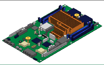
1. Perform the procedure described in Section 3.2, Procedures for Parts Replacement.
2. If necessary, remove the server from the rack.
See Section 3.2.6, Removing a Server From the Rack.
Ensure that you remove all cables as well as the power cords.
See Section 3.2.9, Removing the Rear Cover.
Section 3.2.10, Removing the Bezel.
Section 3.2.11, Removing the Front Cover.
6. (Sun Fire V245) Remove the air baffle.
See Section 3.2.12, (Sun Fire V245) Removing the Air Baffle.
7. Remove any PCI option cards that are installed.
See Section 3.3.1, Removing PCI-E and PCI-X Cards.
8. Remove the PCI-X and PCI-E riser boards (FIGURE 3-18).
FIGURE 3-18 PCI-X and PCI-E Riser Boards - Sun Fire V215
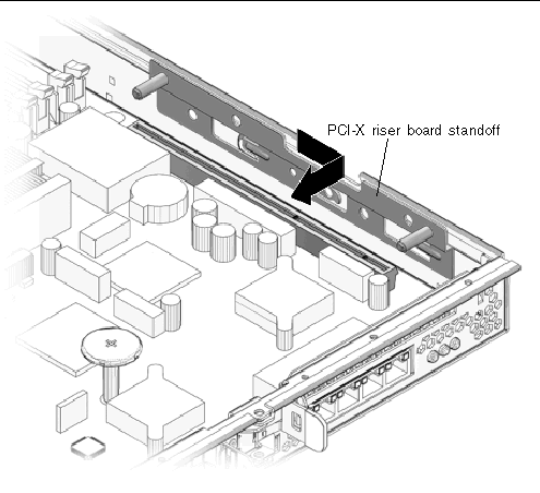
9. (Sun Fire V215) Remove the PCI-X riser board standoff (See FIGURE 3-19 and FIGURE 3-19).
It might be necessary to unlock the PCI-X riser board standoff from the chassis. Press the release and then remove the PCI riser board standoff (FIGURE 3-18).
FIGURE 3-19 PCI-X Riser Board Standoff - Sun Fire V215
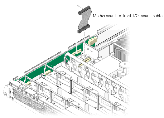
10. Disconnect the motherboard to front I/O board cable (FIGURE 3-20).
This is the cable between the motherboard and the front I/O board.
FIGURE 3-20 Motherboard to Front I/O Board Cable
11. (Sun Fire V215) Remove the screws and the air baffles (FIGURE 3-15).
12. If necessary, make note of the memory configuration so that you can reinstall the memory in the replacement motherboard.
See Section 3.3.5, Removing DIMMs from the motherboard assembly.
See Section 3.3.27, Removing NVRAM.
15. Remove the motherboard/SAS backplane cable connector (FIGURE 3-21).
FIGURE 3-21 Motherboard/SAS Backplane Cable Connector and Screws
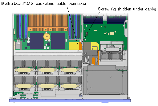
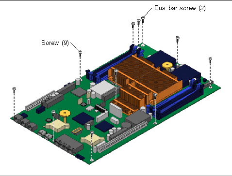
16. Using a No. 2 Phillips screwdriver, remove the 11 screws that secure the motherboard assembly to the chassis (FIGURE 3-22).
The two screws that are installed under the motherboard/SAS backplane cable are black in color. The screws connect the motherboard to the power distribution board through bus bars.
| Note - When you reinstall the motherboard, replace the black screws into the same screw holes. |
FIGURE 3-22 Removing the Motherboard Assembly Screws
17. Using the green handles, slide the motherboard forward and tilt the motherboard assembly to lift it out of the chassis (FIGURE 3-23).
Grab the handles and move the motherboard to the front of the system and lift it out of the chassis.
FIGURE 3-23 Removing the Motherboard Assembly From the Chassis
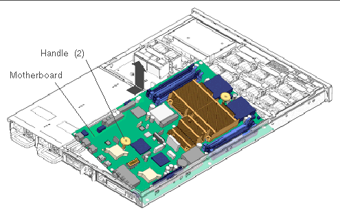
18. Place the motherboard assembly on an antistatic mat.

|
Caution - This procedure requires that you handle components that are sensitive to static discharge. Static discharges can cause the component failures. To avoid this problem, ensure that you follow antistatic practices as described in Section 3.2.7, Performing Electrostatic Discharge - Antistatic Prevention Measures. |
1. Unpackage the replacement motherboard assembly and place it on an antistatic mat.
2. Using the green handles, tilt the motherboard assembly to position it into the chassis (FIGURE 3-24).
When you install the motherboard ensure that you position the board as far forward in the chassis as possible.
FIGURE 3-24 Installing the Motherboard Assembly
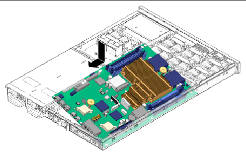
3. Position the motherboard so that its screw holes align with the chassis standoffs.
4. Using the green handles, push down firmly and equally while sliding the motherboard to the rear of the chassis.
5. Install the screws that secure the motherboard to the chassis (FIGURE 3-22).
The two screws that are installed under the motherboard/SAS backplane cable are black in color.
| Note - When you reinstall the motherboard, use only the black screws in screw holes that attach the motherboard to the bus bars. |
6. Reinstall the motherboard/SAS backplane cable to the motherboard (FIGURE 3-21).
7. Reinstall all DIMMs in the motherboard assembly.
| Tip - Only install the DIMMs in the slots (connectors) from which they were removed. See Section 3.3.6, Installing DIMMs. |
See Section 3.3.28, Installing NVRAM.
9. (Sun Fire V215) Reinstall the air baffles for the DIMMs and the screws (FIGURE 3-15).
10. Reinstall the motherboard to front I/O board cable (FIGURE 3-20).
Connect the cable between the front I/O board and the motherboard.
11. (Sun Fire V215) Reinstall the PCI-X riser board standoff (FIGURE 3-19).
12. Reinstall the PCI-E and PCI-X riser boards (FIGURE 3-18).
13. Reinstall any PCI option cards that were removed.
See Section 3.3.2, Installing PCI-E or PCI-X Cards.
14. (Sun Fire V245) Reinstall the air baffle.
See Section 3.2.13, (Sun Fire V245) Installing the Air Baffle.
15. Perform the procedures described in Section 3.4, Procedures for Finishing Up.
1. Perform the procedures described in Section 3.2, Procedures for Parts Replacement.
See Section 3.2.9, Removing the Rear Cover.
See Section 3.2.10, Removing the Bezel.
See Section 3.2.11, Removing the Front Cover.
5. Remove the power supplies from the chassis (FIGURE 3-25).
The power supplies are attached to the power distribution board. Push the power supply latch to the right and pull the power supply out a few inches to disengage it from the power distribution board.
FIGURE 3-25 Power Supply Release Latches - Sun Fire V245

6. Remove the motherboard/SAS backplane cable.
a. (Sun Fire V245 and pre-January 2008 V215 servers) Remove the upper and lower cable retainers (FIGURE 3-24).
The retainers protect the optional DVD super-multi drive, hard drive backplane, and motherboard cable from damage.
FIGURE 3-26 Upper and Lower Cable Retainers and Motherboard/SAS Backplane Cable
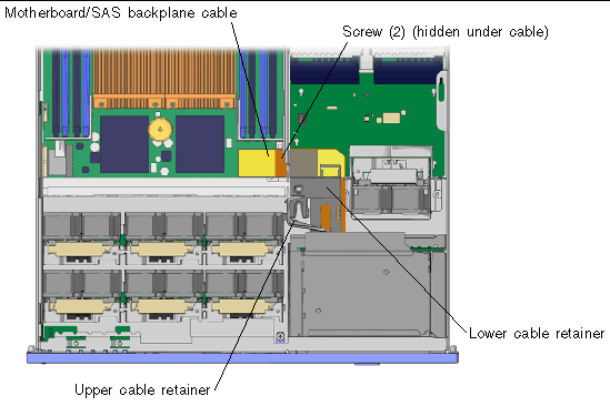
b. (January 2008 V215 servers) Remove the following components (FIGURE 3-27):
FIGURE 3-27 Sun Fire V215 (January 2008) Support Bracket Removal
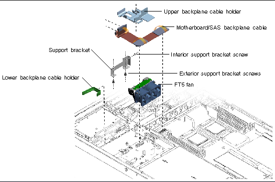
7. Disconnect the motherboard/SAS backplane cable from the power distribution board, hard drive backplane board, motherboard, and if necessary, the optional DVD super-multi drive (FIGURE 3-28).
FIGURE 3-28 Motherboard/SAS Backplane Cable Routing
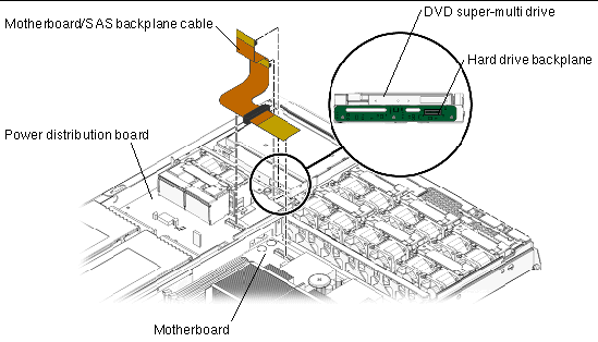
8. Disconnect the cable from connector J6 on the power distribution board (FIGURE 3-39).
9. Remove the hard drive fan tray.
See Section 3.3.21, Removing the Hard Drive Fan Tray.
10. Remove the two screws that attach the hard drive fan cage to the chassis of the server.
11. Remove the hard drive fan tray cage.
12. Remove the three screws that secure the power distribution board to the chassis (FIGURE 3-29).
FIGURE 3-29 Removing the Power Distribution Board
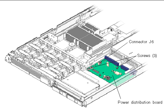
13. Slide the power distribution board toward the front of the chassis and remove it.
14. Place the power distribution board on an antistatic mat.
1. Unpackage the replacement power distribution board and place it on an antistatic mat.
2. Loosely fit the power distribution board onto the locator pins in the chassis and slide the board toward the rear of the chassis (FIGURE 3-29).
3. Reinstall the power distribution board and the three screws.
4. Reconnect the cable from connector J1 on the hard drive fan tray connector board to connector J6 on the power distribution board.
5. Reinstall the hard drive fan tray cage.
6. Reinstall the two screws that attach the hard drive fan cage to the chassis of the server.
7. Reinstall the hard drive fan tray.
See Section 3.3.22, Installing the Hard Drive Fan Tray.
8. Reinstall the motherboard/SAS backplane cable (FIGURE 3-26).
Connect the motherboard/SAS backplane cable to:
9. (January 2008 V215 servers) Reinstall the support bracket components (FIGURE 3-27):
10. (Sun Fire V245 and pre-January 2008 V215 servers) Reinstall the upper and lower cable retainers for the motherboard/SAS backplane cable (FIGURE 3-26).
11. Reinstall the power supplies.
See Section 2.5.2, Installing a Power Supply.
12. Perform the procedures described in Section 3.4, Procedures for Finishing Up.
| Note - After replacing the power distribution board and powering on the system, you must run the setcsn command on an ALOM console to electronically input the chassis serial number. |
1. Perform the procedures described in Section 3.2, Procedures for Parts Replacement.
See Section 3.2.9, Removing the Rear Cover.
See Section 3.2.10, Removing the Bezel.
See Section 3.2.11, Removing the Front Cover.
5. Remove the two screws that secure the front indicator board to the chassis (FIGURE 3-30).
FIGURE 3-30 Removing the Front Indicator Board
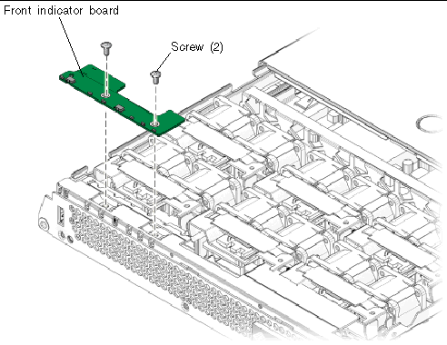
6. Remove the front indicator board.
Slide the board to the right to disconnect it from the front I/O board.
7. Place front indicator board on an antistatic mat.
1. Unpackage the replacement front indicator board and place it on an antistatic mat.
2. Install the front indicator board in the chassis (FIGURE 3-30).
Slide the board to the left to connect it to the front I/O board.
3. Secure the front indicator board to the chassis using two Philips screws.
4. Perform the procedures described in Section 3.4, Procedures for Finishing Up.
1. Perform the procedures described in Section 3.2, Procedures for Parts Replacement.
Only remove the fan trays that are necessary to remove the defective fan tray connector board.
See Section 2.3.1, Removing a Fan Tray).
| Note - Sun Fire V215 servers have two fans for each fan tray. |
3. Remove the Phillips screws that secure the fan tray connector boards to the chassis (FIGURE 3-31).
FIGURE 3-31 Removing the Fan Tray Connector Board
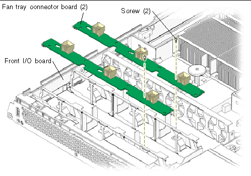
4. Slide the fan tray connector boards to the right to disengage them from the front I/O board.
5. Remove the fan tray connector boards and place the boards on an antistatic mat.
1. Unpackage the replacement fan tray connector boards and place the boards on an antistatic mat.
2. Lower the boards into place and slide the boards to the left to plug the boards into the front I/O board.
3. Secure the boards to the chassis with the Phillips screws.
See Section 2.3.2, Installing a Fan Tray.
| Note - Sun Fire V215 servers have two fans for each fan tray. |
5. Perform the procedures described in Section 3.4, Procedures for Finishing Up.
1. Perform the procedures described in Section 3.2, Procedures for Parts Replacement.
See Section 3.2.9, Removing the Rear Cover.
3. (Sun Fire V245) Remove the air baffle.
See Section 3.2.12, (Sun Fire V245) Removing the Air Baffle.
See Section 3.2.10, Removing the Bezel.
See Section 3.2.11, Removing the Front Cover.
6. Remove the motherboard to front I/O board cable (FIGURE 3-20).
This cable connects the front I/O and motherboards.
See Section FIGURE 2-2, Removing a Fan Tray.
8. Remove the fan tray connector boards from the front I/O board.
See Section 3.3.13, Removing the Fan Tray Connector Boards.
9. Remove the front indicator board.
See Section 3.3.11, Removing the Front Indicator Board.
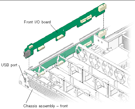
10. Remove the front I/O board (FIGURE 3-32).
FIGURE 3-32 Removing the Front I/O Board
11. Place the front I/O board on an antistatic mat.
1. Unpackage the front I/O board and place it on an antistatic mat.
2. Tip the front I/O board downwards and slightly forward.
3. Push I/O board into place, aligning the board with the chassis (FIGURE 3-32).
When the board is fully seated the USB port is mounted flush against the front of the chassis assembly.
4. Reinstall the front indicator board.
See Section 3.3.12, Installing the Front Indicator Board.
5. Reinstall the fan tray connector boards.
Section 3.3.14, Installing the Fan Tray Connector Boards.
6. Reinstall all six fan trays.
See Section 2.3.2, Installing a Fan Tray.
7. Reinstall the motherboard to front I/O board cable (FIGURE 3-20).
8. (Sun Fire V245) Reinstall the air baffle.
See Section 3.2.13, (Sun Fire V245) Installing the Air Baffle.
9. Perform the procedures described in Section 3.4, Procedures for Finishing Up.
1. Perform the procedures described in Section 3.2, Procedures for Parts Replacement.
See Section 3.2.9, Removing the Rear Cover.
Section 3.2.10, Removing the Bezel.
Section 3.2.11, Removing the Front Cover.
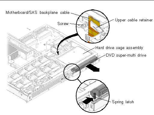
5. Remove the upper cable retainer (FIGURE 3-33).
FIGURE 3-33 Upper Cable Retainer, Motherboard/SAS Backplane Cable, DVD Super-Multi Drive, and Spring Latch
6. Disconnect the motherboard/SAS backplane cable.
Disconnect the motherboard/SAS backplane cable at the connector for the DVD super-multi drive. It is not necessary to disconnect the motherboard/SAS backplane cable from the hard drive backplane or the power distribution board.
7. Push the spring latch to the right and hold (FIGURE 3-33).
Release the spring latch that secures the DVD super-multi drive to the hard drive cage assembly.
8. Remove the DVD super-multi drive from the chassis.
Push the drive from the rear and remove it from the chassis.
9. Place the drive on an antistatic mat.
1. Unpackage the DVD super-multi drive and place it on an antistatic mat.
2. Slide the DVD super-multi drive into the front of the chassis until it seats.
3. Connect the motherboard/SAS backplane cable to the DVD super-multi drive (FIGURE 3-33).
4. Install the upper cable retainer.
5. Perform the procedures described in Section 3.4, Procedures for Finishing Up.
1. Perform the procedures described in Section 3.2, Procedures for Parts Replacement.
2. Remove the optional DVD super-multi drive from the chassis (if installed).
See Section 3.3.17, Removing the DVD Super-Multi Drive.
3. Remove all hard drives from the chassis.
See Section 2.2.1, Removing a Hard Drive.
| Note - Identify the slot in which each hard drive belongs for later installation into the chassis. |
4. Remove the upper and lower cable retainers (FIGURE 3-21).
5. Disconnect the motherboard/SAS backplane cable from the hard drive backplane (FIGURE 3-28).
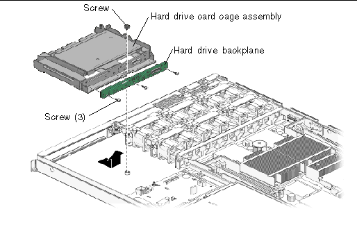
6. (Sun Fire V215) Remove the screw that secures the secures the hard drive assembly and DVD super-multi drive to the chassis (FIGURE 3-34).
7. (Sun Fire V215) Remove the hard drive cage assembly.
The DVD super-multi drive and hard drive assembly are housed together in the hard drive cage assembly. When the screw is removed you can remove hard drive cage assembly from the chassis.
8. (Sun Fire V215) Remove the three screws that secure the SAS drive backplane to the hard drive card cage.
9. (Sun Fire V215) Place the hard drive backplane on an antistatic mat.
FIGURE 3-34 Removing the Hard Drive Backplane - Sun Fire V215
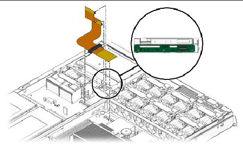
10. (Sun Fire V245) Remove the three screws that secure the hard drive backplane to the hard drive card cage assembly (FIGURE 3-35).
FIGURE 3-35 Removing the Hard Drive Backplane - Sun Fire V245
11. (Sun Fire V245) Remove the hard drive backplane from the chassis and place it on an antistatic mat.
1. Unpackage the replacement hard drive backplane and place it on an antistatic mat.
2. (Sun Fire V215) Install the three screws that secure the hard drive backplane to the hard drive card cage assembly.
| Note - Do not tighten the screws until all three are installed. |
3. (Sun Fire V215) Install the DVD super-multi drive and hard drive assembly into the chassis.
The DVD super-multi drive and hard drive assembly are housed together in the hard drive cage assembly.
4. (Sun Fire V215) Install the screw that secures the hard drive cage assembly to the chassis (FIGURE 3-33).
5. (Sun Fire V245) Use three screws to attach the hard drive backplane to the hard drive cage assembly (FIGURE 3-34).
| Note - Do not tighten the screws until all three of them are in place. |
6. Reinstall the DVD super-multi drive (if necessary).
See Section 3.3.18, Installing the DVD Super-Multi Drive.
7. Connect the motherboard/SAS backplane cable to the replacement hard drive backplane.
8. If necessary, connect the motherboard/SAS backplane cable to the DVD super-multi drive.
9. Install the upper and lower cable retainers (FIGURE 3-21).
10. Reinstall all hard drives in the slots from which you removed them.
If necessary, see Section 2.2.2, Installing a Hard Drive.
11. Perform the procedures described in Section 3.4, Procedures for Finishing Up.
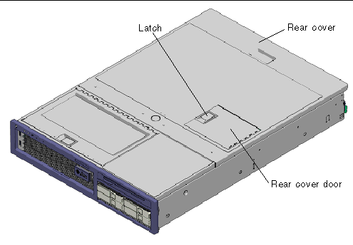
1. Open the rear cover door (FIGURE 3-36).
Lift the rear cover door latch.
FIGURE 3-36 Opening the Rear Cover Door - Sun Fire V245
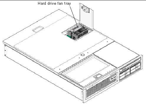
2. Remove the hard drive fan tray (FIGURE 3-37).
| Note - The hard drive fan tray has two fans. |
FIGURE 3-37 Hard Drive Fan Tray - Sun Fire V245
1. Unpackage the replacement hard drive fan tray and place it on an antistatic mat.
2. Open the rear cover door (FIGURE 3-36).
Lift the latch to open the door.
3. Install the hard drive fan tray (FIGURE 3-37).
Ensure that the fan connector securely mates with the connector on the fan tray connector board.
| Note - The hard drive fan tray has two fans. |
5. Perform the procedures described in Section 3.4, Procedures for Finishing Up.
1. Perform the procedures described in Section 3.2, Procedures for Parts Replacement.
Section 3.2.9, Removing the Rear Cover.
3. Remove the hard drive fan tray.
See Section 3.3.21, Removing the Hard Drive Fan Tray.
FIGURE 3-38 Hard Drive Fan Tray Cage and Screws
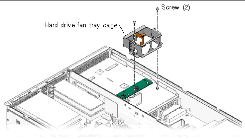
4. Remove the two screws (FIGURE 3-38).
These screws attach the fan tray cage to the chassis of the server.
5. Remove the hard drive fan tray cage.
6. Disconnect the cable from connector J1 (FIGURE 3-39).
This cable connects connector J1 on the hard drive fan tray connector board to connector J6 on the power distribution board.
FIGURE 3-39 Hard Drive Fan Tray Connector Board - Connector J1
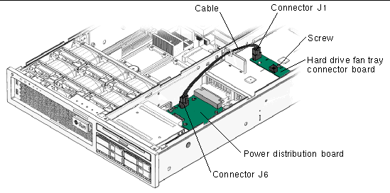
This screw secures the hard drive fan tray connector board to the chassis.
8. Remove the hard drive fan tray connector board.
1. Unpackage the replacement hard drive fan tray connector board and place it on an antistatic mat.
2. Install the hard drive fan tray connector board (FIGURE 3-39).
This screw secures the board to the chassis.
4. Connect the cable between the hard drive fan connector board and the power distribution board.
This cable connects connector J1 on the hard drive fan tray connector board to connector J6 on the power distribution control board.
5. Install the hard drive fan tray cage (FIGURE 3-38).
These screws secure the hard drive fan tray cage to the chassis.
7. Install the hard drive fan tray.
See Section 3.3.22, Installing the Hard Drive Fan Tray.
8. Perform the procedures described in Section 3.4, Procedures for Finishing Up.
1. Perform the procedures described in Section 3.2, Procedures for Parts Replacement.
See Section 3.2.9, Removing the Rear Cover.
3. If necessary, remove any PCI or PCI-X cards.
See Section 3.3.1, Removing PCI-E and PCI-X Cards.
4. Remove the plastic insulator from the heat sinks.
5. (Sun Fire V245) Remove the air baffle.
See Section 3.2.12, (Sun Fire V245) Removing the Air Baffle.
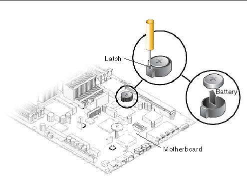
6. Using a small (No. 1 flat-blade) screwdriver, press the latch and remove the battery from the motherboard (FIGURE 3-40).
FIGURE 3-40 Removing the Battery
1. Unpackage the replacement battery.
2. Press the new battery into the motherboard (FIGURE 3-40).
Install the positive side (+) facing upward, away from the motherboard.
3. Reinstall the plastic insulator on the heat sinks.
4. If necessary, reinstall the PCI and PCI-X cards.
See Section 3.3.2, Installing PCI-E or PCI-X Cards.
5. (Sun Fire V245) Install the air baffle.
See Section 3.2.13, (Sun Fire V245) Installing the Air Baffle.
6. Perform the procedures described in Section 3.4, Procedures for Finishing Up.
7. Use the ALOM setdate command to set the day and time.
Use the setdate command before you power on the host system.
1. Perform the procedures described in Section 3.2, Procedures for Parts Replacement.
See Section 3.2.9, Removing the Rear Cover.
3. If necessary, remove the PCI and PCI-X cards.
See Section 3.3.1, Removing PCI-E and PCI-X Cards.
4. Remove the plastic insulator for the heat sinks.
5. (Sun Fire V245) Remove the air baffle.
See Section 3.2.12, (Sun Fire V245) Removing the Air Baffle.
6. Locate the NVRAM (FIGURE 3-41).
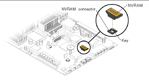
7. Pull the NVRAM straight up from the connector.
NVRAM and the NVRAM connector are keyed.
| Note - The server will not function correctly without NVRAM installed. |
1. Unpackage the replacement NVRAM and set it on an antistatic mat.
2. Locate the NVRAM connector (FIGURE 3-41).
3. Align the NVRAM module with the NVRAM connector.
| Note - NVRAM and the NVRAM connector are keyed. |
4. Press the NVRAM down until it seats.
5. Reinstall the plastic insulator for the heat sinks.
6. If necessary, reinstall the PCI and PCI-X cards.
See Section 3.3.2, Installing PCI-E or PCI-X Cards.
7. (Sun Fire V245) Install the air baffle.
See Section 3.2.13, (Sun Fire V245) Installing the Air Baffle.
8. Perform the procedures described in Section 3.4, Procedures for Finishing Up.
If you removed the front cover or bezel perform these steps:
2. Install the front cover. (FIGURE 3-43).
(Sun Fire V245) The interlock switch is actuated when the front cover is installed.
3. Slide the front cover to the rear until it seats.
4. Position the bezel on the front of the chassis and snap it into place (FIGURE 3-42).
FIGURE 3-42 Installing the Bezel
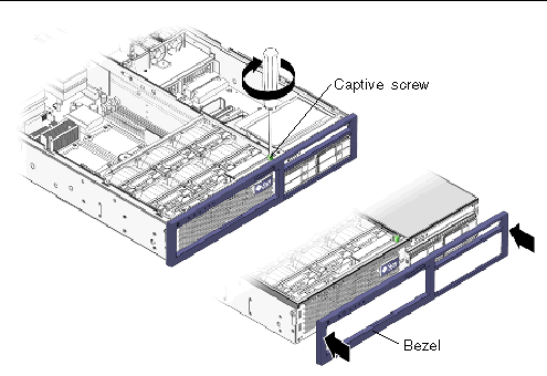
5. Tighten the captive screw to secure the bezel to the chassis.
6. Close the front cover door.
FIGURE 3-43 Installing the Front Cover - Sun Fire V245 Server
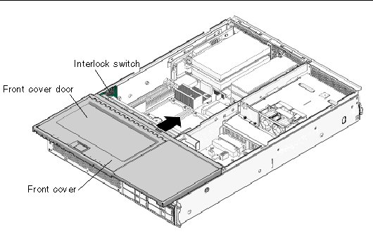
| Note - The interlock switch for the Sun Fire V215 servers is actuated when the rear cover is installed. |
If you removed the rear cover, perform these steps:
1. Place the rear cover on the chassis.
Set the cover down so that it hangs over the rear of the server by about an inch (25.4 mm).

|
Caution - When installing the rear cover do not damage the interlock switch (Sun Fire V215 and V245 servers). |
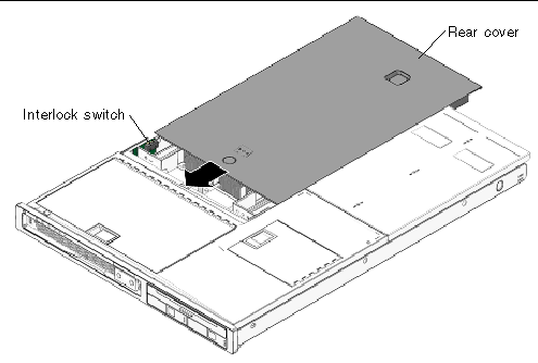
2. Slide the rear cover forward until it seats (FIGURE 3-44).
| Note - The interlock switch for the Sun Fire V215 and V245 servers is actuated when the rear cover is installed. |
FIGURE 3-44 Installing the Rear Cover - Sun Fire V215 server
If you removed the server chassis from the rack, perform these steps.

|
Caution - The servers are heavy. Two people might be required to carry the chassis and install it in the rack. |
1. On the rack, ensure that the slide rails are extended.
2. Place the ends of the chassis mounting brackets into the slide rails (FIGURE 3-45).
FIGURE 3-45 Returning the Server to the Rack
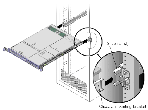
3. Slide the server into the rack until the brackets lock into place.
The server is now in the extended maintenance position.
If you extended the server to the maintenance position, use this procedure to return the server to the normal rack position.
1. Release the slide rails from the fully extended position by pushing the release tabs on the side of each rail (FIGURE 3-46).
FIGURE 3-46 Release Tabs - Rails
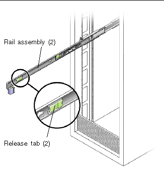
2. While pushing on the release tabs, slowly push the server into the rack.
Ensure that the cables do not get in the way.
3. Reconnect the cable management arm (CMA) into the back of the rail assembly:
| Note - Refer to the Sun Fire V215 and V245 Server Installation Guide for detailed CMA installation instructions. |
a. Insert the smaller extension into the clip located at the end of the mounting bracket (FIGURE 3-47).
FIGURE 3-47 Installing the Cable Management Arm (CMA)
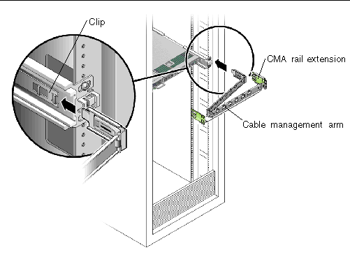
b. Plug the CMA rail extension into the end of the left rail assembly.
The tab at the front of the rail extension clicks into place.
4. Reconnect the cables to the back of the server.
If the CMA is in the way, disconnect the left CMA release and swing the CMA open.
5. Reconnect all cables that were removed from the rear of the server.
 Reconnect both power cords to the power supplies.
| Note - As soon as the power cords are connected, standby power is applied. Depending on the configuration of the firmware, the system might boot. |
Copyright © 2008, Sun Microsystems, Inc. All Rights Reserved.