| C H A P T E R 1 |
|
System Overview |
This chapter introduces you to the Sun Fire V445 server and describes its features. The following sections are included:
The Sun Fire V445 server is a high-performance, shared memory, symmetric multiprocessing server that supports up to four UltraSPARC® IIIi processors and uses the Fire ASIC PCIe NorthBridge along with PCI-X and PCIe expansion slots. The UltraSPARC IIIi processor has a 1 Mbyte L2 cache and implements the SPARC® V9 Instruction Set Architecture (ISA) and the Visual Instruction Set extensions (Sun VIS software) that accelerate multimedia, networking, encryption, and Java software processing. The Fire ASIC provides higher I/O performance and interfaces with the I/O subsystem, which contains 4 10/100/1000Mb Ethernet ports, 8 SAS disk drives, 1 DVD-RW drive, 4 USB ports, a POSIX compliant DB-9 serial port, and service processor communication ports. The PCI expansion subsystem is configurable with a variety of plug-in third party adapters.
System reliability, availability, and serviceability (RAS) are enhanced by features that include hot-pluggable disk drives and redundant, hot-swappable power supplies and fan trays. RAS features are described in Chapter 5.
The system, which is mountable in a 4-post rack, measures 6.85 inches high (4 rack units - U), 17.48 inches wide, and 25 inches deep (17.5 cm x 44.5 cm x 64.4 cm). The system weighs approximately 75 lb (34.02 kg). Robust remote access is provided with Advanced Lights Out Manager (ALOM) software, which also controls powering on/off and diagnostics. The system also meets ROHS requirements.
TABLE 1-1 provides a brief description of the Sun Fire V445 server features. More details on these features are provided in the following subsections.
|
16 slots that can be populated with one of the following types of |
|
|
|
|
8 2.5 inch (5.1 cm) high, hot-pluggable Serial Attached SCSI (SAS) disk drives |
|
|
8 PCI slots: four 8 lane PCIe slots (2 of which also support 16 lane form factor cards) and 4 PCI-X slots |
|
|
4 550-watt hot-swappable power supplies, each with its own cooling fan |
|
|
6 hot-swappable high-power fan trays (one fan per tray) organized into three redundant pairs - 1 redundant pair for disk drives - 2 redundant pairs for the CPU/memory modules, memory DIMMs, I/O subsystem, and front-to-rear cooling of the system |
|
|
A serial port for the ALOM management controller card and a 10BASE-T network management port for remote access to system functions and the system controller |
|
|
Robust reliability, availability, and serviceability (RAS) features are supported. See Chapter 5 for details. |
|
Processing power is provided by up to four CPU/Memory modules. Each module incorporates one UltraSPARC IIIi processor, and slots for four double data rate (DDR) dual inline memory modules (DIMMs).
System main memory is provided by up to 16 DDR synchronous dynamic random access memory DIMMs. The system supports 512-Mbyte, 1-Gbyte, and 2-Gbyte DIMMs. Total system memory is shared by all CPUs in the system and ranges from a minimum of 1 Gbyte (one CPU/memory module with two 512-Mbyte DIMMs) to a maximum of 32 Gbytes (four modules fully populated with 2-Gbyte DIMMs). For more information about system memory, see DIMMs.
The Sun Fire V445 server provides four Gigabit Ethernet ports, one 10BASE-T network management port, two Serial ports, and four USB ports.
The four on-board Gigabit Ethernet ports located on the back panel support several modes of operations at 10, 100, and 1000 megabits per second (Mbps). Additional Ethernet interfaces or connections to other network types can be provided by installing the appropriate PCI interface cards. Multiple network interfaces can be combined with Solaris Internet Protocol (IP) network multipathing software to provide hardware redundancy and failover capability, as well as load balancing on outbound traffic. Should one of the interfaces fail, the software can automatically switch all network traffic to an alternate interface to maintain network availability. For more information about network connections, see Configuring the Primary Network Interface and Configuring Additional Network Interfaces.
The network management port (labeled NET MGT) is located on the chassis back panel. This port is reserved for use with the ALOM system controller and the system console.
This port provides direct network access to the ALOM system controller card and its firmware. This port also provides access to the system console, power-on self-test (POST) output messages, and ALOM system controller messages. Use this port to perform remote administration, including externally initiated resets (XIR).
The DB-9 port is POSIX compliant with a general-purpose DB-9 connector (labeled TTYB) on the system back panel. The serial management port is an RJ-45 connector (labeled SERIAL MGT) on the chassis back panel, and is reserved for use with the ALOM system controller and the system console.
The serial management port enables you to set up a system console device, without configuring an existing port. All power-on self-test (POST) and ALOM system controller messages are directed to the serial management port by default. For more information, see About the Serial Ports.
The front and back panels both provide two Universal Serial Bus (USB) ports for connecting peripheral devices such as modems, printers, scanners, digital cameras, or a Sun Type-6 USB keyboard and mouse. The USB ports are USB 2.0 compliant, and support 480 Mbps, 12 Mbps, and 1.5 Mbps speeds. For additional details, see About the USB Ports.
Internal disk storage is provided by up to eight 2.5 inch (5.1 cm) high, hot-pluggable, SAS disk drives. The basic system includes a SAS disk backplane that accommodates eight disks capable of data transfer rates of up to 320 megabytes per second. See About the Internal Disk Drives and Locating Back Panel Features.
External multidisk storage subsystems and redundant array of independent disks (RAID) storage arrays can be supported by installing peripheral component interconnect (PCI) host adapter cards along with the appropriate system software. Software drivers supporting SCSI and other types of devices are included in the Solaris OS. In addition, the system supports internal hardware mirroring (RAID 0,1) using the on-board SAS controller. See About RAID Technology.
System I/O is handled by two expanded Peripheral Component Interconnect (PCIe) buses and two PCI-X buses. The system has eight PCI slots: four 8 lane PCIe slots (two of which also support 16 lane form factor cards) and four PCI-X slots. The PCI-X slots operate at up to 133 MHz, are 64-bit capable, and support legacy PCI devices. All PCI-X slots comply with PCI Local Bus Specification Rev 2.2 and PCI-X Local Bus Specification Rev 1.0. All PCIe slots comply with PCIe Base Specification r1.0a and PCI Standard SHPC Specification, r1.1. For additional details, see About the PCI Cards and Buses.
The basic system includes four 550-watt power supplies, each with its own cooling fan. The power supplies are plugged into a separate power distribution board (PDB). This board is connected to the motherboard through 12-volt high current bus bars. Two power supplies provide sufficient current (1100 DC watts) for maximum configuration. The other power supplies provide 2+2 redundancy, enabling the system to continue operating if up to two power supplies fail.
The power supplies are hot-swappable - you can remove and replace a faulty power supply without shutting down the system. With four separate AC inlets you can wire the server with a fully redundant AC circuit. A failed power supply does not need to remain installed to sustain proper cooling. For more information about the power supplies, see About the Power Supplies.
The system is equipped with six fan trays organized into three redundant pairs. One redundant pair is for cooling the disk drives. The other two redundant pairs are for cooling the CPU/Memory modules, memory DIMMs, I/O subsystem, and provide front-to-rear cooling of the system. Not all fans must be present to provide adequate cooling - only one fan per redundant pair must be present.
| Note - All system cooling is provided by the fan trays - power supply fans do not provide system cooling. |
See About the System Fan Trays for details.
The Sun ALOM system controller card enables system management and administration for the Sun Fire V445 server over a serial line or an Ethernet network. The ALOM system controller provides remote system administration for geographically distributed or physically inaccessible systems. These features include powering on/off the system and enabling diagnostics. The firmware installed on the ALOM system controller card enables you to monitor the system, without having to install any supporting software.
The ALOM system controller card runs independently of the host system, and operates off of standby power from the systems power supplies. This allows the ALOM system controller to serve as a lights out management tool that continues to function even when the server operating system goes offline or when the server is powered off.
The SAS controller supports hardware disk mirroring and striping (RAID 0,1) capabilities for all internal disk drives, resulting in improved disk drive performance, data integrity, data availability, and fault recovery.
Sun Fire V445 servers with Solaris 10 or later feature the latest fault management technologies. With Solaris 10, Sun introduces a new architecture for building and deploying systems and services capable of predictive self-healing. Self-healing technology enables Sun systems to accurately predict component failures and mitigate many serious problems before they actually occur. This technology is incorporated into both the hardware and software of the Sun Fire V445 server.
At the heart of the Predictive Self-Healing capabilities is the Solaris Fault Manager, a service that receives data relating to hardware and software errors, and automatically and silently diagnoses the underlying problem. Once a problem is diagnosed, a set of agents automatically responds by logging the event, and if necessary, takes the faulty component offline. By automatically diagnosing problems, business-critical applications and essential system services can continue uninterrupted in the event of software failures, or major hardware component failures.
The Sun Fire V445 server provides faster computing in a denser, more power-efficient package. The following key new features are included:
The UltraSPARC IIIi CPU provides a faster JBus system interface bus that considerably enhances system performance.
The Sun Fire V445 server provides higher I/O performance with PCIe cards integrated with the latest Fire chip (NorthBridge). This integration allows higher bandwidth and lower latency datapaths between the I/O subsystem and the CPUs. The server supports two full height or low profile/full depth 16 lane (wired 8 lane) PCIe cards and two full height or low profile/half depth 8 lane PCIe cards. The system also supports four PCI-X slots that operate at up to 133 MHz, are 64-bit capable, and support legacy PCI cards.
The Fire ASIC is a high-performance JBus to PCIe host bridge. On the host bus side, Fire supports a coherent, split transaction, 128-bit JBus interface. On the I/O side, Fire supports two 8 lane serial PCIe interconnects.
Compact 2.5-inch disk drives provide faster, denser, more flexible, and more robust storage. Hardware RAID 0/1 is supported across all eight disks.
The Sun Fire V445 server provides robust remote access to system functions and the system controller. The physical system contol keyswitch has been removed and the switch settings (power on/off, diagnostic mode) are now emulated with ALOM and software commands.
Other new features include the following:
The illustration below shows the system features that you can access from the front panel.
FIGURE 1-1 Front Panel Features
For information about front panel controls and indicators, see Front Panel Indicators.
The system is configured with up to eight disk drives, which are accessible from the front of the system.
Several front panel indicators provide general system status, alert you to system problems, and help you to determine the location of system faults.
During system startup, the indicators are toggled on and off to verify that each one is working correctly. Indicators located on the front panel work in conjunction with specific fault indicators. For example, a fault in the power supply subsystem illuminates the power supply Service Required indicator on the affected power supply, as well as the system Service Required indicator. Since all front panel status indicators are powered by the system's standby power source, fault indicators remain lit for any fault condition that results in a system shutdown.
At the top left of the system as you look at its front are six system status indicators. Power/OK indicator and the Service Required indicator provide a snapshot of the overall system status. The Locator indicator helps you to quickly locate a specific system even though it may be one of numerous systems in a room. The Locator indicator/button is at the far left in the cluster, and is lit remotely by the system administrator, or toggled on and off locally by pressing the button.
FIGURE 1-2 Front Panel System Status Indicators
Each system status indicator has a corresponding indicator on the back panel.
Listed from left to right, the system status indicators operate as described in the following table.
|
|
This white indicator is lit by a Solaris command, Sun Management Center command, or ALOM commands to help you locate the system. There is also a Locator indicator button that allows you to reset the Locator indicator. For information on controlling the Locator indicator, see Controlling the Locator Indicator. |
|
|
|
This amber indicator lights steadily when a system fault is detected. For example, the system Service Required indicator lights when a fault occurs in a power supply or disk drive. In addition to the system Service Required indicator, other fault indicators might also be lit, depending on the nature of the fault. If the system Service Required indicator is lit, check the status of other fault indicators on the front panel and other FRUs to determine the nature of the fault. See Chapter 8 and Chapter 9. |
|
|
|
This green indicator blinks slowly then quickly during startup. The Power/OK indicator lights continuosly when the system power is on and the Solaris Operating System is loaded and running. |
TABLE 1-3 lists additional fault indicators, and describes the type of service required.
For hard disk drive indicator descriptions, see TABLE 4-4. For fan tray indicator descriptions located on the top panel of the server, see TABLE 4-6.
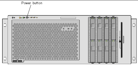
The system Power button is recessed to prevent accidentally turning the system on or off. If the operating system is running, pressing and releasing the Power button initiates a graceful software system shutdown. Pressing and holding down the Power button for four seconds causes an immediate hardware shutdown.

|
Caution - Whenever possible, use the graceful shutdown method. Forcing an immediate hardware shutdown can cause disk drive corruption and loss of data. |

FIGURE 1-3 Power Button Location
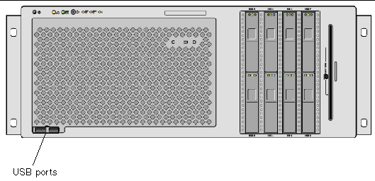
The Sun Fire V445 server has four Universal Serial Bus (USB) ports: two on the front panel, and two on the back panel. All four USB ports comply with the USB 2.0 specification.

For more information about the USB ports, see About the USB Ports.
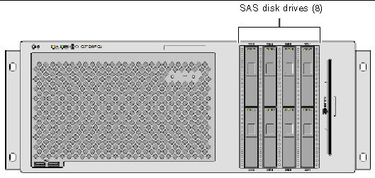
The system has up to eight hot-pluggable internal SAS disk drives.

FIGURE 1-5 Hard Disk Drives Location
For more information about how to configure internal disk drives, see the About the Internal Disk Drives.
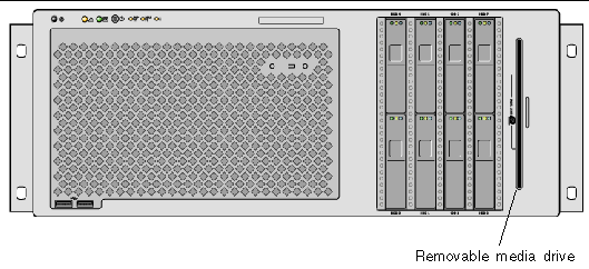
The Sun Fire V445 server has a DVD-ROM drive in a removable media bay. This drive also has DVD-RW and CD-RW capabilities.

FIGURE 1-6 Removable Media Drive Location
For more information about servicing the DVD-ROM drive, see the Sun Fire V445 Server Service Manual.
The illustration below shows the system features that are accessible from the back panel.
FIGURE 1-7 Back Panel Features
The back panel system status indicators consist of the Locator indicator, Service Required indicator, and the System Activity indicator. These indicators are located in the bottom center of the back panel, and operate as described in TABLE 1-2.

For power supply indicator descriptions, see TABLE 4-5. For fan tray indicator descriptions located on the top panel of the server, see TABLE 4-6.
There are four AC/DC redundant (N+N) and hot-swappable power supplies, where two power supplies are sufficient to power a fully configured system.
For more information about power supplies, see the following sections in the Sun Fire V445 Server Service Manual:
For more information about power supplies, see About the Power Supplies.
The Sun Fire V445 server has four PCIe slots and four PCI-X slots. (One of the PCI-X slots is occupied by the LSI Logic 1068X SAS controller.) These are labeled on the back panel.
For more information about how to install a PCI card, see the Sun Fire V445 Server Service Manual.
For more information about PCI cards, see About the PCI Cards and Buses.
There are two system controller ports. Both use an RJ-45 connector.
FIGURE 1-9 Network and Serial Management Port Locations
This port provides direct network access to the ALOM system controller, when configured, and can access the ALOM prompt and system console output.
| Note - The system controller is accessed through the serial management port by default. You must reconfigure the system controller to use the network management port. See Activating the Network Management Port. |
The network management port has a Link indicator that operates as described in TABLE 1-4.
|
This green indicator is lit when an Ethernet connection is present. |
The serial management port provides the default connection to the system controller and can access the ALOM prompt and system console output. You can connect to the serial management port using a VT100 terminal, a tip connection, or a terminal server.
FIGURE 1-10 System I/O Port Locations
There are two USB ports on the back panel. These comply with the USB 2.0 specification.
For more information about the USB ports, see About the USB Ports.
The Sun Fire V445 server has four Gigabit Ethernet ports.
FIGURE 1-11 Gigabit Ethernet Port Locations
Each Gigabit Ethernet port has a corresponding status indicator, described in TABLE 1-5.
There is a POSIX compliant DB-9 serial port labeled TTYB. In addition, you may configure the RJ-45 serial management port as a conventional serial port. See About the Serial Ports.
The Sun Fire V445 server provides the following RAS features:
See Chapter 5 for information on how to configure these features.
Sun Cluster software enables you to connect up to eight Sun servers in a cluster configuration. A cluster is a group of nodes that are interconnected to work as a single, highly available and scalable system. A node is a single instance of Solaris software. The software can be running on a standalone server or on a domain within a standalone server. With Sun Cluster software, you can add or remove nodes while online, and mix and match servers to meet your specific needs.
Sun Cluster software delivers high availability through automatic fault detection and recovery, and scalability, ensuring that mission-critical applications and services are always available when needed.
With Sun Cluster software installed, other nodes in the cluster will automatically take over and assume the workload when a node goes down. The software delivers predictability and fast recovery capabilities through features such as local application restart, individual application failover, and local network adapter failover. Sun Cluster software significantly reduces downtime and increases productivity by helping to ensure continuous service to all users.
The software lets you run both standard and parallel applications on the same cluster. It supports the dynamic addition or removal of nodes, and enables Sun servers and storage products to be clustered together in a variety of configurations. Existing resources are used more efficiently, resulting in additional cost savings.
Sun Cluster software allows nodes to be separated by up to 10 kilometers. This way, in the event of a disaster in one location, all mission-critical data and services remain available from the other unaffected locations.
For more information, see the documentation supplied with the Sun Cluster software.
Sun Management Center software is an open, extensible system monitoring and management tool. The software is written in Java and uses Simple Network Management Protocol (SNMP) to provide enterprise-wide monitoring of Sun servers and workstations, including their subsystems, components, and peripheral devices.
For more information, see About Sun Management Center.
Copyright © 2007, Sun Microsystems, Inc. All Rights Reserved.