Chapter 2 Cabling the System
This chapter contains instructions for installing the fiber cable organizer, cabling the system, and connecting the power cord to the AC power supply.
Preparing the System for Cabling
Make sure the server is in an area that allows access to both the front and rear of the chassis. This site should conform to site preparation guidelines and specifications covered in Chapter 1, Preparing for Installation.
Installing the Fiber Cable Organizer
Use the fiber cable organizer to route the fiber optic cable to connect the interface board and the I/O+ board. A 2-meter cable is required when utilizing the internal FC-AL disk drives. The cable organizer can help prevent damage to the fiber optic cable by helping ensure the 1.0 inch minimum bend radius rule is observed.
The fiber cable organizer kit includes two organizer sections and one screw. To install the cable organizer:
-
Remove the screw securing the power cord retainer clip to the support bracket at the rear of the system.
-
Orient one of the fiber cable organizer sections with the spool facing toward you. Set the hooks on the back of the organizer into the corresponding cutouts on the right side of the support bracket.
The top of the brace should be flush with the top of the support bracket. The organizer will extend below the bracket. See Figure 2-1.
-
Secure the organizer by pushing it outward along the support bracket until the snap at the rear of the organizer clicks audibly into place.
-
Install the left spool brace by repeating step 2 and step 3.
-
Using the screw included in the kit, fasten the spool braces to the support bracket through the center front cut out formed when both braces are in place.
-
Remount the retainer clip through the hex nut at the notch on the side of the organizer.
Set the retainer clip screw into the hex nut.
-
To wrap the 2-meter fiber cable around the organizer spools to interconnect the interface board and the I/O+ board for FC-AL disks, see "Wrapping the Fiber Cable on the Organizer".
Figure 2-1 Fiber Cable Organizer Mounted on Support Bracket
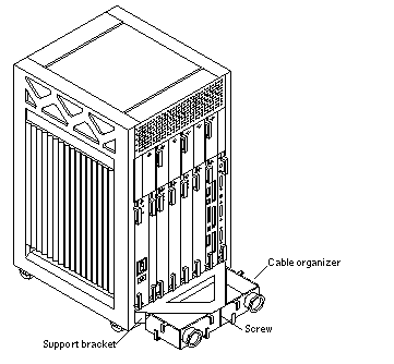
Connecting the Power Cord
-
Use the key provided with your system to unlock and open the Enterprise 3500 system front door.
-
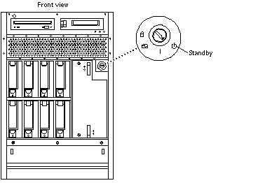
Locate the system key switch in the upper right corner, insert the key provided, and turn the key switch to the Standby position. See Figure 2-2.
Figure 2-2 Key Switch Standby Position
-
Turn the AC power switch to Off.
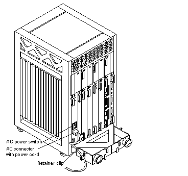
This switch is at the rear of the system, on the peripheral power supply/AC (PPS/AC) that is installed in the far left corner (Figure 2-3).
-
Connect the female end of the power cord into the AC connector.
This connector is at the rear of the system, on the PPS/AC, just below the AC power switch (Figure 2-3).
-
Route the power cord through the power cord retainer clip.
In Step 6 of "Installing the Fiber Cable Organizer ", you reattached the plastic clip to the cable organizer that you mounted on the rear support bracket (Figure 2-3).
-
Connect the male end of the power cord into a grounded outlet.
The outlet must be a 100-120 or 220-240 VAC 15A circuit.
Figure 2-3 AC Power Switch, AC Connector, and Retainer Clip
 Caution -
 Do NOT turn on power to the unit yet. Doing so can cause system damage to occur.
See the next sections to connect the network cable to the system, and to connect the system to the network.
Connecting the Network Cable to the System
The locations specified in the following instructions assume the use of twisted-pair 10BASE-T or 100BASE-T Ethernet.
-
Locate the network cable.
Figure 2-4 shows the twisted-pair Ethernet network cable.
Figure 2-4 Network Cable

-
Connect one end of the network cable into the RJ-45 twisted-pair network port.
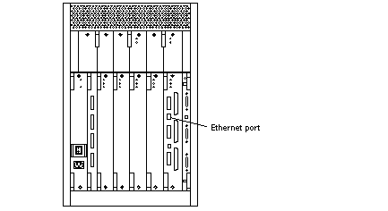
For 10/100BASE-T Ethernet, the default interface port is the onboard connector on the I/O+ board in slot 1 (Figure 2-5).
Figure 2-5 10/100BASE-T Ethernet Connection
Connecting the System to the Network
-
Connect the network cable to a twisted-pair-to-transceiver interface box.
-
Connect the interface box with an appropriate cable to a network transceiver.
Figure 2-6 shows a typical arrangement for connecting the system to an Ethernet network.
-
For Ethernet cables, determine if the cable has N-type screw-on connectors at the ends.
-
If the Ethernet cable lacks N-type connectors at the ends, use a "vampire" tap to connect the cable to the transceiver (Figure 2-6). To connect the cable to the transceiver, use instructions provided with the vampire tap.
-
If the Ethernet cable has N-type connectors, connect the Ethernet cable to the transceiver:
-
-
Determine if a terminator should be installed. Table 2-1 lists the cabling limitations for Ethernet.
-
If termination is required, install a 50-ohm terminator in the unused transceiver N connector or at the end of the coaxial cable. Use a female double N-type connector.
Figure 2-6 shows the elements used in the installation process.
Figure 2-6 Connecting Twisted Pair Ethernet to N-type Coaxial Cable

Table 2-1 lists the cabling limitations for Ethernet.
Table 2-1 Ethernet Cabling Limitations for N-type Coaxial CableCable Segment
Length in Meters
Allowed contiguous length of cable segments
23.4
70.2
117.0
500.0 (1)
Distance between transceivers (multiples-of)
2.5 (2)
Minimum length of Ethernet coaxial cable segments
23.4
Maximum length of transceiver "drop" cable
50.0
Minimum length of twisted pair cable
no minimum
Maximum length of twisted pair cable
110
Note -(1) Finite lengths (as constrained by transmission line phenomena). Minimum length = 23.4M; maximum = 500M. If cable falls shorter than one of these values, add cable to achieve next-highest value.
(2) Transceivers are placed at intervals of 2.5 meters, or multiples of 2.5 meters along the Ethernet cable. Example: transceivers are connected 2.5 meters apart, not 2.0 meters. Example: transceivers are connected 15 meters apart (6 multiples of 2.5 meters), not 14.0 meters.
Figure 2-7 shows an example of a typical network setup. The Enterprise 3500 system can be any server shown in this figure.
Figure 2-7 Ethernet Cabling Length -- Example Using N-type Cable

Note -Sun equipment conforms to the Ethernet 10/100BASE-T standard, which states that the 10/100BASE-T Link Integrity Test function should always be enabled on both the host and the hub. If you have problems verifying connection between Sun equipment and your hub, verify that your hub also has the link test function enabled. Refer to Section 8.6.1, "Failure of Network Communications," in the Sun Enterprise 3500 System Reference Manual (part number 805-2630), and refer to the manual provided with your hub for more information about the Link Integrity Test function.
-
If all cables are connected, power on the system.
Connecting an ASCII Terminal
An ASCII terminal (or workstation) can be attached to the server to display diagnostic messages produced by the firmware (power-on self-test/POST or OpenBoot(TM) PROM/OBP) program. A terminal is not required for normal server operations, so it may be necessary to locate a terminal to connect to the server.
-
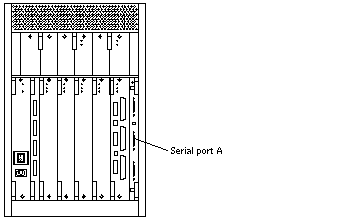
Connect the terminal cable into serial port A on the clock+ board. See Figure 2-8.
Figure 2-8 Clock+ Board
-
Connect the terminal power cord into an AC wall outlet.
-
Configure the ASCII terminal as follows:
-
9600 bps
-
1 stop bit
-
8 data bits
-
Parity off
-
Full duplex
Refer to the instruction manual shipped with the terminal for specific configuration instructions.
Note -The setup parameters listed in Step 3 may differ from the setup at the customer site. These parameters can be changed in the NVRAM (nonvolatile random access memory). Refer to the set-defaults and printenv commands in the OpenBoot Command Reference manual, part number 802-3242.
-
Connecting the Fiber Cable to the I/O+ Board
-
Remove the two plastic caps that cover the cable connector on the GBIC module.
-
Remove the plastic cap covering the ends of the fiber cable.
-
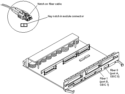
Connect one end of the fiber cable into the GBIC module installed on the I/O+ board.
Align the notch in the cable connector with the key notch in the module connector. See Figure 2-9.
-
Connect the other end of the fiber cable into the GBIC connector on the SPARCstorage(TM) Array (or other storage device with fiber optic interface) rear panel.
Align the notch in the cable connector with the notch in the connector on the storage device rear panel.
Figure 2-9 Fiber Cable and Fibre Card Connectors and Ports on the I/O+ Board
Connecting the Fiber Cable to the Interface Board and the I/O+ Board
Internal FC-AL disk drives require an interface board (IB) to communicate via the I/O+ board. Figure 2-10 identifies the GBIC ports on the interface board, and Table 2-2 identifies the GBIC associated with each disk drive.
Figure 2-10 Interface Board
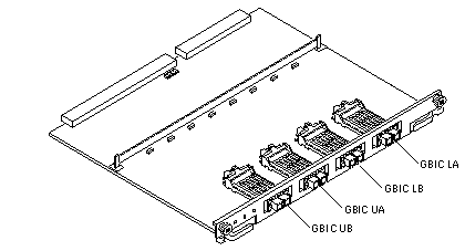 Table 2-2 GBIC Controllers for Disk Drive Ports
|
Disk Drives |
Drive Port |
GBIC Name and Location |
|---|---|---|
|
0, 1, 2, 3 |
A |
GBIC LA (Lower bank) |
|
0, 1, 2, 3 |
B |
GBIC LB (Lower bank) |
|
4, 5, 6, 7 |
A |
GBIC UA (Upper bank) |
|
4, 5, 6, 7 |
B |
GBIC UB (Upper bank) |
Note -
Reserve disk bay 0 for the boot disk.
Wrapping the Fiber Cable on the Organizer
To ensure that the fiber optic cable minimum bend radius rule (1.0 inch) is observed, use this procedure to wrap the cable around the spool organizer:
-
Remove the two plastic caps that cover the cable connector on the GBIC module.
-
Remove the plastic cap covering the ends of the fiber cable.
-
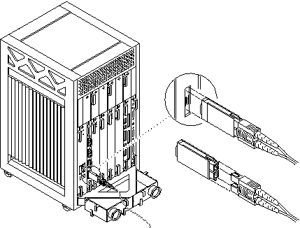
Connect one end of the fiber cable into the GBIC module installed on the interface board rear panel.
Use the IB diagram and GBIC controllers table above to identify the GBIC for the disk drive. Align the notch in the cable connector with the key notch in the GBIC module connector. See Figure 2-11.
Figure 2-11 Fiber Cable Ports on the Interface Board
-
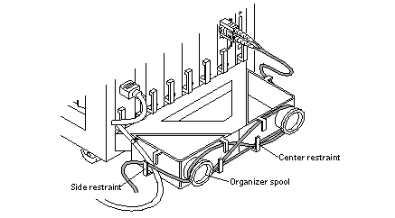
Route the fiber cable down toward the bottom of the system, placing it through the left side restraints on the organizer.
-
Wrap the cable around the fiber cable organizer spools (mounted on the system rear support bracket) in a "figure 8" pattern as follows:
Wrap the cable around the bottom of the left spool and then up and around the right spool, threading the cable through the center restraints on the organizer.
Thread the cable back through the center restraints, then down and around the left spool.
Figure 2-12 Fiber Cable in "Figure 8" Pattern
-
Repeat step 5 until the cable is the desired length, finishing on the right side. Thread the cable through the right side restraints and connect it to the I/O+ board.
Connecting External SCSI Devices
External SCSI-2 devices connect to your system through the built-in single-ended Fast/Wide SCSI-2 port on I/O+ boards (except for the board in slot 1), or through FSBE/S, DSBE/S, SWIS/S, or DWIS/S SBus cards installed on I/O+ boards.
Note -
The onboard SCSI-2 bus on the I/O+ board in slot 1 controls internal media tray devices. Therefore, the external SCSI connector on the I/O+ board in slot 1 must always have a terminator installed.
Note -
The maximum combined length for a string of SCSI cables is 6 meters for non-differential cables. For differential SCSI cables, the maximum is 25 meters. When calculating the total length of a SCSI string, include external cables, internal cables, and printed traces. Table 2-3 lists internal measurements for the Enterprise servers.
Table 2-3 Internal SCSI Lengths (Approximate)
|
Location |
Internal Length |
|---|---|
|
SBus+ I/O board |
0.43 meter |
|
Graphics+ I/O board |
0.43 meter |
For information on device addressing, priorities, and slot assignments, refer to "Rules for System Configuration" in the Sun Enterprise 3500 System Reference Manual, part number 805-2630.
Risk of equipment damage. Do not assign the same SCSI address to two devices sharing the same SCSI bus or SBus card.
To connect an external SCSI device to your system:
-
Connect a SCSI cable to the appropriate SCSI-2 host on the I/O+ board.
-
For the I/O+ board in slot 1, this is an SBus card installed in an appropriate SBus slot.
-
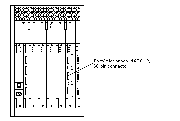
For I/O+ boards in slots 2 through 5, use the onboard SCSI-2 port or an SBus card installed in an appropriate SBus slot. Figure 2-13 shows the location of the onboard single-ended SCSI connector on the I/O+ board.
Figure 2-13 Onboard Single-ended SCSI Connector on the I/O+ Board
-
-
Connect the other end of the SCSI cable to the external SCSI-2 device.
-
Power on the system and test the server.
- © 2010, Oracle Corporation and/or its affiliates
