Chapter 1 Preparing for Installation
This chapter describes how to prepare your site for these systems:
-
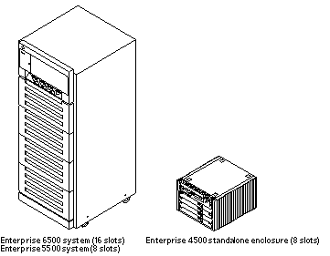
Sun Enterprise 6500 system--16-slot cabinet server
-
Sun Enterprise 5500 system-- 8-slot cabinet server
-
Sun Enterprise 4500 system-- 8-slot standalone server
Figure 1-1 Sun Enterprise 6500/5500/4500 Systems
The tasks for installing the systems are:
-
Unpacking the cabinet server -- Chapter 1
-
Preparing the site -- Chapter 1
-
Preparing the servers -- Chapter 1
-
Cabling -- Chapter 2
-
Powering on -- Chapter 3
-
Using the software -- Chapter 4
Note -
For information about physical specifications, electrical specifications, and environmental requirements, refer to Appendix A, "Specifications, in the Sun Enterprise 6500/5500/4500 Systems Manual.
Unpacking the Enterprise 6500/5500 Cabinet Systems
Note -
Inspect all shipping cartons for evidence of physical damage. If a shipping carton is damaged, request that the carrier's agent be present when the carton is opened. Keep all contents and packing material for the agent's inspection.
If you have a standalone Enterprise 4500 system, or the cabinet is already unpacked, go to "Preparing the Electrical Circuits".
Note -
Any unpacking instructions printed on the outside of the shipping carton take precedence over instructions in this section.
If your cabinet system is on a wooden pallet, extend the cabinet levelling pads so that the cabinet cannot roll. If the original shipping pallet has side rails, it is not necessary to lower the levelling pads.
-
Cut the plastic or metal straps that are around the shipping container and lift off the corrugated top.
Store the shipping materials for future shipments.
-
Remove the sides of the container.
The container is held together by six plastic clips. To unlock a clip, press the two inner tabs together and pull out the entire clip.
-
Remove inner packing materials from the top and corners of the cabinet.
-
At the front of the pallet, lift the Velcro(TM) strip at each end of the wooden bar to detach the bar, then set it aside.
-
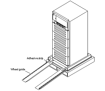
Slide out the two wooden ramps from under the cabinet.
-
Attach the wooden ramps to the pallet using the Velcro strip that is attached to each ramp.
Ensure both wheel guides (wooden strips) are to the outside. See Figure 1-2.
 Caution -
 Three or more people are needed to move the server cabinet safely. Two people must push at the front of the cabinet to control the movement of the cabinet.
 Caution -
 To prevent the cabinet from tipping over, push or pull only on the upper half of the cabinet.
Figure 1-2 Attaching the Ramps to the Shipping Pallet
Shipping and Storing the System
Save the original shipping containers and packing materials in case you need to store or ship your system.
If you cannot store the shipping materials, recycle or dispose of the materials properly. Consult your local recycling authority for information.
Preparing the Electrical Circuits
In planning where to place your equipment, remember that each of the following items requires access (by way of a separate power cord) to a power outlet:
-
Sun Enterprise 6500/5500/4500 system
-
External peripherals
-
Monitor used for diagnostics
Enterprise 6500/5500 Cabinet Systems
The 16-slot and 8-slot system cabinets require a 30A circuit and a detachable cable.
The equipment relies on the protective device in the building installation; thus it requires a 30A circuit breaker.
Do not attach other electrical equipment to the server AC circuit; server reliability may be affected.
Note -
If the appropriate electrical receptacle is not available in your country, the plug may be removed from the cord. The cord can then be permanently connected to a dedicated branch circuit by a qualified electrician. Check local electrical codes for proper installation requirements.
The system cabinet has a high leakage current to ground. Strictly observe the following instructions to reduce the risk of electric shock.
The system requires an electrical circuit that is grounded to earth. The UL1950, CSA950, and EN60950 specify:"An insulated earthing conductor that is identical in size, insulation material, and thickness to the earthed and unearthed branch-circuit supply conductors, except that it is green with or without one or more yellow stripes, is to be installed as part of the branch circuit that supplies the unit or system. The earthing conductor described is to be connected to earth at the service equipment or, if supplied by a separately derived system, at the supply transformer or motor-generator set.""The attachment-plug receptacles in the vicinity of the unit or system are all to be of an earthing type, and the earthing conductors serving these receptacles are to be connected to earth at the service equipment.""(Information Technology Equipment -- UL 1950, copyright 1989, 1991 by Underwriters Laboratories, Inc.)"
The power cord provides a ground path that will protect the drives and boards in the cabinet from static electricity damage.
Do not make mechanical or electrical modifications to the server cabinet. Sun Microsystems\256 is not responsible for the regulatory compliance if the cabinet is modified.
Enterprise 4500 System
The 8-slot Enterprise 4500 system uses nominal input voltages of 100-120 VAC or 200-240 VAC. Sun products are designed to work with single-phase power systems having a grounded neutral conductor.
To reduce the risk of electrical shock, do not plug Sun products into another type of power source. Contact your facilities manager or a qualified electrician if you are unsure what type of power is supplied to your building.
Preparing the Air Conditioning
For the most reliable system operation:
-
The room should have sufficient air-conditioning capacity to support the cooling needs of the entire system.
-
The air-conditioning system should have controls that prevent excessive temperature changes.
Preparing the Ethernet Network
The Enterprise 6500/5500/4500 systems follow the IEEE standard for 10/100BASE-T Ethernet (twisted-pair) or MII (Media Independent Interface).
Twisted-pair cables used with Sun Microsystems products have RJ-45 connectors that resemble the smaller RJ-11 connectors used for modular telephone cables. For twisted-pair cable length, see Chapter 2, Table 2-1.
A MII to AUI converter cable, available from Sun, enables the 10/100 Mbps Ethernet interface to run over 10 Mbps coaxial Ethernet networks. Other MII Ethernet connectivity products are available from third parties.
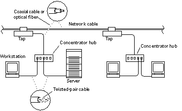
Figure 1-3 and Figure 1-4 illustrate types of network cables and possible implementations of 10/100BASE-T Ethernet.
Set up the network using Sun or third-party components. To obtain the best results, read any applicable manufacturer instructions. Be aware that Sun Microsystems cannot guarantee the performance of any components that are not purchased from Sun.
Figure 1-3 Types of Network Cables Used
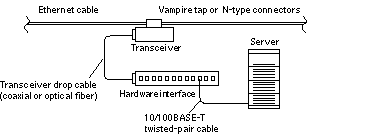
Figure 1-4 Example of 10/100BASE-T (Twisted-Pair) Ethernet
Note -
Multiplexer boxes require a transceiver when used with the Ethernet applications described in this manual. Although these transceivers are compatible with Sun equipment, Sun Microsystems does not guarantee the performance of any component that was not purchased from Sun.
Many transceivers are compatible with both level-1 and level-2 Ethernet. To operate these transceivers with Sun equipment, set the device for level-2 operation following the manufacturer's instructions.
Sun equipment conforms to the Ethernet 10/100BASE-T standard, which states that the 10/100BASE-T Link Integrity Test function should always be enabled on both the host and the hub. If you have problems verifying connection between Sun equipment and your hub, verify that your hub also has the link test function enabled. See "Failure of Network Communications", and refer to the manual provided with your hub.
Preparing the Area
Enterprise 6500/5500 Cabinet Systems
-
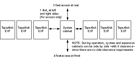
Server cabinets require approximately 4 feet (120 cm) of space in front and 3 feet (90 cm) in back (Figure 1-5) for access by service personnel.
-
Server and expansion cabinets can be placed next to each other, without space between them, since there are no side clearance requirements during operation. To access and remove side panels, however, allow approximately 1 foot (30 cm) of space on the sides.
-
The server system (including expansion cabinets) should have a dedicated AC breaker panel. The server system should not share this breaker panel with other, unrelated equipment.
-
Keep power and interface cables out of the way of foot traffic. Cables can be routed inside walls, floors, ceilings, or in protective channels. Interface cables should be routed away from motors and other sources of electric/magnetic or radio frequency interference.
-
If the cabinet is installed on a raised floor, conditioned air should be directed to the bottom of each rack through perforated panels.
Figure 1-5 Cabinet Server Access Areas -- Top View
Enterprise 4500 System
The Enterprise 4500 system is designed to sit on the floor, on a caster base, or on a desk or table.
Note -
Do not stack multiple Enterprise 4500 systems directly on top of each other.
Follow these guidelines to prepare a location.
-
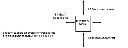
The server unit requires approximately 1.5 feet (50 cm) of space in the front and back for access by service personnel. See Figure 1-6.
-
A minimum space of 6 inches (16 cm) is required on both sides of the server to afford adequate air flow.
-
A minimum space of 3 feet (90 cm) is recommended to avoid exhaust air recirculation if systems are placed next to each other.
To avoid recirculating exhaust air from one system into another, do not put systems or peripherals side by side closer than 3 feet (90 cm).
-
Keep power and interface cables clear of foot traffic. Route cables inside walls, under the floor, through the ceiling, or in protective channels. Route interface cables away from motors and other sources of magnetic or radio frequency interference.
Figure 1-6 Standalone Server Access Areas -- Top View
Preparing the Enterprise 6500/5500 Cabinet Systems
You need the following tools:
-
#1 Phillips screwdriver
-
Levelling wrench (packed inside the system cabinet)
-
Front panel key (packed in a bag in the accessory box)
Moving the Server
The server weighs at least 835 pounds (375 kg). Observe the following precautions when moving the server.
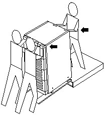
Three or more people are needed to move the server cabinet safely. Two people must push at the front of the cabinet Figure 1-7) to control the movement of the cabinet.
To prevent the cabinet from tipping over, push or pull only on the upper half of the cabinet.
Figure 1-7 Moving the Server Safely Down the Ramps
Adjusting the Levelling Pads
After moving the cabinet to its operating location, adjust the levelling pads.
-
Remove the levelling wrench from inside the server cabinet.
The levelling wrench is attached to the cabinet frame by a reusable plastic strap. Press the plastic tab to unlock the plastic strap around the wrench, then slide part of the strap through the lock to loosen the wrench. Do not cut the strap.
-
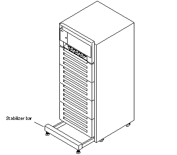
Fully extend the stabilizer bar (Figure 1-9) from the bottom of the cabinet.
-
Screw the two stabilizer bar levelling pads down until they are 1/8- to 1/4-inch (three to six millimeters) above the floor.
Make sure both pads are at equal heights above the floor. This clearance allows an extended stabilizer bar to stop the cabinet if it should begin to tilt.
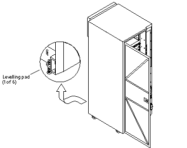
Figure 1-8 Levelling Pad
-
Slide the stabilizer bar into the cabinet.
 Caution -
 Always extend the stabilizer bar before pulling the disk drive trays out for servicing.
-
Adjust the four levelling pads on the cabinet frame. The four pads should press against the floor so that the cabinet does not move.
To adjust levelling pads on the cabinet rear, you may have to remove the kick panel. Two captive screws attach the panel to the cabinet (Figure 1-8).
This completes the first part of the system installation.
-
If you are unable to continue the installation at this time, secure the levelling wrench inside the cabinet and close the rear door.
Figure 1-9 Stabilizer Bar
Adding Storage Devices
For hole numbers for mounting screws for Sun disk arrays and other storage trays and devices, refer to the Rackmount Placement Matrix, Sun part number 802-6945.
Unless otherwise specified in the Rackmount Placement Matrix, mount the heaviest subassemblies at the bottom of the racks to minimize the effects of earthquakes.
Refer to the installation guide for the storage device for additional instructions.
Preparing the Enterprise 4500 System
The server weighs more than 150 lbs (68 kg). Two people are needed to lift the server safely.
You need the following tools:
-
#1 Phillips screwdriver
-
Front panel key (packed in a bag in the accessory box)
Follow the graphic instructions on the shipping container to remove the server from the container. The front panel key and the power cord are in the shipping container.
Labelling the System
The front of the server has an area for a label where you can list the system name or other information. The document set includes gray paper that is suitable for a label.
To add a label to the front of the system:
-
Remove the top front bezel.
Refer to the Sun Enterprise 6500/5500/4500 Systems Reference Manual for details:
-
Enterprise 6500/5500 systems: refer to the section, "Top Front Bezel."
-
Enterprise 4500 system: refer to the section, "Top Bezel."
-
-
Snap out the narrow transparent window.
From the rear side of the bezel, gently squeeze the top and bottom edges together as you simultaneously push the transparent window out through the front of the bezel.
-
Choose the information that will appear on the label.
Common items include the name of the server, IP address, name and contact information for the system administrator, and the group of users that the machine services.
-
Use the colored paper provided with the system to make a label.
Print or write the desired information and cut the label to fit the transparent window. The label should be 12 mm x 150 mm (0.5 in x 5.9 in).
-
Place the label inside the window, and snap the window back in place from the front side of the bezel.
- © 2010, Oracle Corporation and/or its affiliates
