Tape and CD-ROM Drives
Use and Maintenance
Refer to the documentation that came with your device for information on use and maintenance. The procedures for the use and maintenance of these devices are the same for the different Enterprise systems, whether the devices are mounted horizontally (as in the Enterprise 4500 system) or vertically (as in the Enterprise 5500 and 6500 systems).
Enterprise 6500/5500 Tape or CD-ROM Drive
To remove and replace an existing device, perform steps 1 through 5. To install a tape device for the first time, proceed to step 6.
To prevent breakage, do not grasp the panel by the bottom edge.
-
Remove the key from the key switch.
-
Remove the top panel.
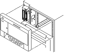
Grasp the panel on both sides at the top and pull to disengage the ball studs (FIGURE 8-4).
Figure 8-3 Removing the Top Front Panel

Note -It is not necessary to remove the media tray to replace a device; it is only necessary to remove the device enclosure from the media tray.
-
Remove the left side panel.
See Section 12.3.6 "Side Panels for removal instructions.
-
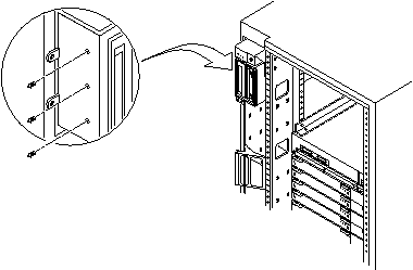
Release the device enclosure from the media tray by removing three screws on the left side of the media tray (FIGURE 8-5).
-
Pull the device enclosure forward and disconnect the data and power cables from the rear of each device.
Figure 8-4 CD-ROM/Tape Drive Removal and Replacement

-
After the cabling is removed, remove the device enclosure from the media tray.
-
To remove a drive:
-
CD-ROM drive: remove two screws from each side where the device is secured to the device enclosure. Proceed to Step 9.
-
Tape drive: remove 2 screws from each side where the tape is fastened to the device enclosure, and then remove 4 screws securing the device to the enclosure side plate. Proceed to Step 9.
-
-
To install a tape drive in an unused slot:
-
On the replacement device set the SCSI ID address to 6 (for a CD-ROM drive) or 5 (for a tape drive).
-
To complete installation of a CD-ROM or tape drive, reverse Step 2 through Step 5.
Enterprise 4500 Tape or CD-ROM Drive
To remove and replace an existing device, perform steps 1 through 5. To install a tape drive for the first time, proceed to step 6.
Note -
For cooling purposes, the tape drive must be installed on the side nearest the key switch.
-
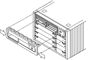
Unlock and remove the front panel bezel.
-
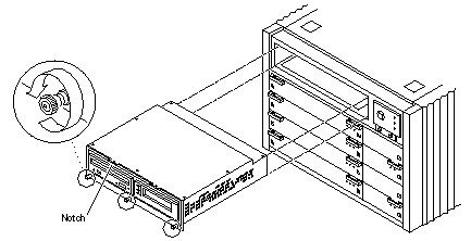
Loosen the bottom three captive screws that hold the media tray to the chassis tray (FIGURE 8-7).
-
Insert a screwdriver in the notch (FIGURE 8-7) at the top center of the media tray to pull out the tray and separate it from the rear slip connectors.
-
Remove the seven screws on top of the media tray to lift off the tray cover to access CD-ROM and tape drives.
Figure 8-5 Removing the Front Panel Bezel

Figure 8-6 Removing and Replacing the media tray

-
To remove and replace a CD-ROM or a tape drive:
-
Loosen the three captive screws securing the device to the tray.
-
Remove the mounting plate of the device being replaced and attach it to the replacement device using the same screws.
-
Set the replacement device SCSI address to 6 for a CD-ROM drive, or 5 for a tape drive.
-
Secure the replacement device to the caddy by tightening the three captive screws on the mounting plate.
-
To complete the replacement, reverse Step l and Step 2.
Note -The tape drive must be installed on the side nearest the key switch for cooling purposes.
-
-
To install a tape drive for the first time:
-
Remove the filler panel by loosening the three captive screws and then removing the panel.
-
Separate the filler panel plate from the device mounting bracket by loosening and removing the four screws; discard the filler panel plate.
-
Secure the mounting bracket to the new device.
-
Set the SCSI address to 5.
-
Secure the device and the mounting bracket to the media tray using the three captive screws.
-
To complete the install, reverse Step l and Step 2 of this procedure.
-
- © 2010, Oracle Corporation and/or its affiliates
