Chapter 12 Preparing for Service
This chapter contains information about preparing the system for service after the system has been powered off.
Servicing Hot-Pluggable Components
Hot-pluggable components can be removed and replaced without powering off the system. For information about disconnecting and connecting hot-pluggable components that require service, see "Hot-Plug Feature".
Powering Off the System
See "Powering Off the System".
Internal Access-Enterprise 6500/5500 Systems
The Enterprise 6500/5500 system cabinet panels consist of the following:
-
CD/Tape device door
-
Top bezel
-
Front panels--hinged door consisting of three vented panels
-
Rear screen panel
-
Two side panels
-
Fan tray screen cover
-
Kick panel
-
Stabilizer bar
Outer Cover Reference Guide
Use Table 12-1 as a guide to determine which panels to remove to access replaceable parts for the Enterprise cabinet systems
Table 12-1 Cover Removal by Assembly|
|
CD/Tape Device Door |
Top Bezel |
Front Door |
Rear Door |
Left Side Panel |
Right Side Panel |
Kick Panel |
Fan Tray Screen Cover |
|---|---|---|---|---|---|---|---|---|
|
SCSI Compartment |
X |
|
|
|
|
|
|
|
|
Tape Tray or Tape Library |
|
X |
|
|
|
|
|
|
|
Fan Tray |
|
|
|
|
|
|
|
X |
|
Control Board |
|
|
X |
|
|
|
|
|
|
Centerplane |
|
X |
X |
X |
|
|
|
|
|
AC Power Sequencer |
|
|
|
|
|
|
X |
|
|
External Cables |
|
|
|
X |
|
|
X |
|
|
CPU/Memory Board |
|
|
X |
|
|
|
|
|
|
I/O+ or Disk Boards |
|
|
|
X |
|
|
|
|
|
Disk Arrays |
|
|
X |
X |
|
|
|
|
CD-ROM/Tape Device Door
The small door to the left of the top panel can contain a CD-ROM drive and/or a tape drive.
To open the door, push on the top right corner of the door. The clasp will release and the door will spring open.
To close the door, press gently to engage the clasp.
Top Front Bezel
The top front bezel is retained by chassis-mounted ball studs.
To avoid breaking the plastic bezel, do not grasp the bezel by the bottom edge.
Figure 12-1 Removing the Front Bezel
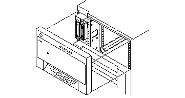
Removing the Top Front Bezel
-
Remove the key from the key switch.
-
Grasp the bezel on both sides at the top and pull the bezel away from the ball studs (Figure 12-1).
-
Set the bezel aside.
Replacing the Top Front Bezel
-
Place the bezel against the chassis with ball studs aligned with the catches on the bezel, and tap or press both sides of the bezel into place.
-
Insert the key into the key switch.
Front Door
Figure 12-2 Opening the Front Door
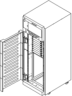
Opening the Front Door
The door is hinged on the left side. The door swings open if pulled firmly on the right side of the top panel.
Removing the Front Door
-
Remove the top bezel. See "Top Front Bezel".
-
Open the hinged door fully (past the bracket), and lift the door free of the bracket.
Rear Door and Kick Panel
If it is necessary to remove the rear door, pull out the two hinge pins (Figure 12-3) and lift the rear door away from the cabinet.
Interface cables should be placed behind the kick panel. To remove the kick panel, loosen the two captive screws.
Figure 12-3 Removing the Rear Door
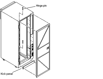
Side Panels
To remove the side panels:
-
Loosen two slotted-head captive screws near the panel base.
-
Tilt the panel bottom out.
-
Lift the panel up until free of the tabs at the top of the chassis.
Figure 12-4 Removing the Side Panels
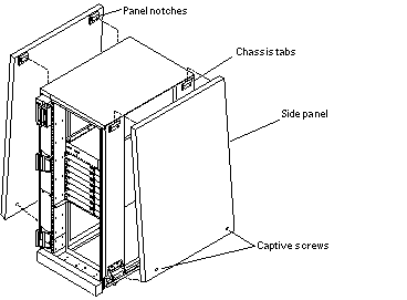
To replace the side panels:
-
Place the panel against the cabinet so the notches on the panel inside align with tabs at the chassis top.
-
Lower the panel into place and allow it to hang flush against the chassis.
-
Tighten the two captive screws at the panel base.
Fan Tray and Screen
Fan Tray Screen
-
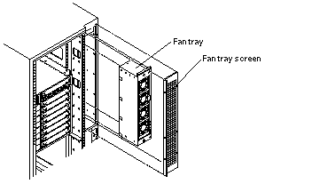
Loosen the four screws on the left and the four screws on the right of the fan tray screen (Figure 12-5).
It is not necessary to completely remove the screws.
Figure 12-5 Removing the Fan Tray Screen and Fan Tray
-
Lift the screen up until the slotted screw holes clear the screw heads.
To replace the fan tray screen, reverse these instructions.
Fan Tray
-
Loosen the two captive fasteners on the fan tray.
-
Remove the power cable and fan fail cable.
To keep the cables out of the way, feed them down through the opening below the fan tray area.
-
Pull the fan tray back, tilting the top out so that it clears the chassis.
To replace the fan tray, reverse these instructions.
Stabilizer Bar
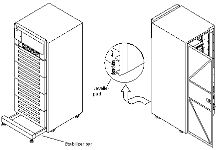
The cabinet has six levelling pads. Four pads on the cabinet frame are lowered to touch the floor and prevent the cabinet from rocking. Two levelling pads are part of the stabilizer bar and should not touch the floor.
-
Extend the stabilizer bar fully from the bottom of the cabinet (Figure 12-6).
Figure 12-6 Stabilizer Bar and Levelling Pads
-
Screw the two stabilizer bar levelling pads down until they are 1/8- to 1/4-inch (3 to 6 mm) above the floor.
Ensure both pads are at equal heights above the floor. This clearance allows the stabilizer bar to slide in and out easily, yet catch the cabinet if it should begin to tilt.
 Caution -
 Always extend the stabilizer bar before pulling the disk drive trays out for servicing.
Internal Access--Enterprise 4500 System
The top bezel must be removed to access the media tray and the key switch tray.
Top Bezel
To remove the top bezel:
-
Remove the key from the key switch.
-
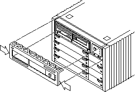
Grasp the bottom corners of both sides of the top bezel and pull it toward you.
Apply inward pressure (Figure 12-7) to release the snap locks on each side.
Figure 12-7 Removing the Top Bezel/Panel
-
Tilt the top bezel upward to a 45o angle and remove the bezel.
To replace the top bezel, reverse these instructions.
Media Tray
To remove the media tray:
-
Remove the top bezel.
-
Loosen the three captive screws that hold the tray in place.
-
Insert a screwdriver in the notch at the top center of the media tray (Figure 12-8) to pull out the tray..
-
Remove the seven screws on top of the media tray (Figure 12-8) to lift off the tray cover to access CD and tape drives.
Figure 12-8 Removing the Media Tray
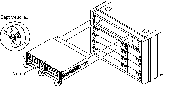
To replace the media tray, reverse these procedures.
Powering On the System
All of the panels should be in place before you turn on the electical power. See "Restarting the System", to power-on.
- © 2010, Oracle Corporation and/or its affiliates
