System Overview
The Enterprise 6500, 5500, and 4500 servers all use variations of the same general card cage design. All systems feature shared-memory multiprocessors and use the same boards, power/cooling modules (PCMs), and operating software.
Board Types
All systems use the same board types, with the exception of load boards and filler panels.
-
The CPU/Memory+ board supports up to two UltraSPARC II modules and 16 SIMM slots.
-
The SBus+ I/O board includes two SYSIO ASICs that provide two SBuses: one for two plug-in SBus cards and two GBIC (100 MB/sec Fibre Channel) interfaces, and one for one plug-in SBus card and the onboard devices (10/100 Mbit TPE and Single-ended Fast/Wide SCSI).
-
The Graphics+ I/O board includes one SYSIO ASIC that provides a single SBus for two plug-in SBus cards, two GBIC (100 MB/sec Fibre Channel) interfaces, and the onboard devices (10/100 Mbit TPE and Single-ended Fast/Wide SCSI).
-
The PCI+ I/O board has two PCI bus connectors, each of which can accommodate a PCI riser card. Each riser card accommodates one PCI short card. In addition, onboard devices provide Fast Ethernet (10/100 Mbit) and Fast/Wide SCSI interfacing.
-
In the Enterprise 6500 system, empty board slots require load boards (part number 501-3142) to reduce the possibility of RFI generation. The Enterprise 5500 and 4500 systems use filler panels (part number 540-2592).
Basic Definitions for the Card Cage
When locating a board slot in the 8-slot and 16-slot card cages, remember:
Table B-1 Card Cage Definitions|
Slot numbers |
Even-numbered slots are at the front of the card cage. Odd-numbered slots are at the back. |
|
|
In the front of the card cage, slot 0 is at the top. At the rear of the card cage, slot 1 is at the top. |
|
|
The component side of a board is down in the front slots. The component side is up in the rear slots. |
|
|
For specific slot numbers, see Appendix B, "Enterprise 4500 Standalone Server". |
|
Slot functions |
All card cage slots are equivalent in the Enterprise 6500, 5500, and 4500 systems. However, it is suggested that you install I/O+ boards at the back of the cage to simplify the installation of interface cables. Install CPU/Memory+ boards at the front of the cage to leave the rear slots for I/O+ boards. If all slots are filled on one side of the cage, you can use the other side. |
|
|
Slot 1 should contain an I/O+ board connected to the boot disk. (This is a suggestion, and not a requirement.) |
|
|
Slot 0 should contain a CPU/master board with at least one CPU. The POST diagnostics display more messages if slot 0 contains a CPU/Memory+ board and a CPU. For an explanation, see the next item, "Master board." |
|
Master board |
The first CPU/Memory+ board (in slot 0) functions temporarily as a master board during some POST tests. There is no master board during normal system operations after the POST tests have finished. |
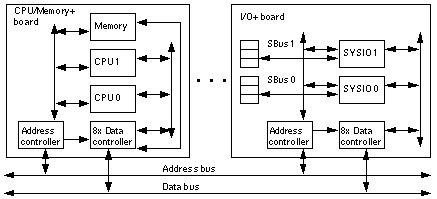
Enterprise card cages feature a centerplane bus. Boards at the front of the centerplane must be installed component side down, while boards at the back must be installed component side up. The boards are oriented this way to allow for minimum signal trace lengths and optimum system performance.
Figure B-1 illustrates the logical organization of Enterprise systems.
Figure B-1 Enterprise System Logical Organization

There are few differences between board slots and each slot can accept any board type. However, an I/O+ board should be installed in slot 1 since this slot connects directly to the internal media tray through the centerplane and related cables. The internal tape and/or CD-ROM or other optional internal SCSI drives cannot be used unless an I/O+ board is present in slot 1.
Although the remaining slots are equivalent, I/O+ boards should be located on the back side of the centerplane for easy access to interface cables at the rear of the cabinet.
- © 2010, Oracle Corporation and/or its affiliates
