System Packaging
This section describes the features of the system enclosures.
Enterprise 6500 Server
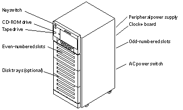
The Enterprise 6500 server features a 16-slot card cage in a 68-inch data center system cabinet (Figure B-2).
Figure B-2 Sun Enterprise System Cabinet

The front of the cabinet contains the CD-ROM/tape tray, the keyswitch, the even-numbered board slots, and the even-numbered power/cooling module (PCM) slots.
The rear of the cabinet contains the AC power switch, the peripheral power supply, the clock+ board, the odd-numbered board slots, and the odd-numbered PCM slots.
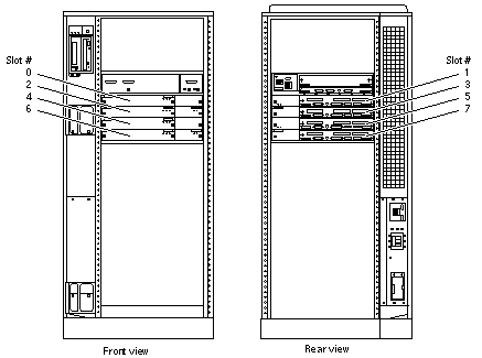
For slot numbers in the 16-slot card cage, see Figure 3-5.
Air circulation for the system boards is provided by the power/cooling modules. The PCMs (PCM 0 through PCM 7) have two fans each. The fans provide cooling for the PCM, plus two adjacent board slots. There is also a fan tray in the card cage (item 11 in Figure F-2). A second fan tray is located at the side of the rack (Figure F-7), The rear of the media tray also has a fan.
All empty board slots must be blocked by load boards for proper airflow, cooling, and EMI protection. Other types of empty slots must be blocked by filler panels.
Enterprise 5500 Server
The Enterprise 5500 server is similar to the Enterprise 6500 system but features a shorter, 8-slot, card cage. See Figure B-2.
For slot numbers in the 8-slot card cage, see Figure B-3.
Figure B-3 Enterprise 5500 Server

Functionally, the 16-slot and 8-slot cabinet servers are the same, with the only difference being the board capacity and amount of internal space available below the card cage. All boards are interchangeable between the two versions.
All empty slots must be blocked by filler panels for proper airflow, cooling, and EMI protection.
Note -
The load board that is required for the 16-slot Enterprise 6500 server is not required for the Enterprise 5500.
Enterprise 4500 Standalone Server
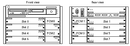
The Enterprise 4500 server uses the 8-slot card cage that is used for the Enterprise 5500, but the card cage is in a standalone cabinet (Figure B-4).
Also note that several areas of the card cage that are covered by filler panels in the cabinet version are used in the standalone version. These areas include the SCSI CD-ROM/tape tray, keyswitch, and AC switch (Figure B-4).
The power/cooling modules (PCM 0 through PCM 3) each have two fans. The fans provide cooling for the PCM and the two adjacent board slots. Air circulation for the system boards is provided by the power/cooling modules. In addition, the Enterprise 4500 has a combined AC input box and fan tray.
All empty slots must be blocked by filler panels for proper airflow, cooling, and EMI protection.
Figure B-4 Enterprise 4500 Standalone Server

- © 2010, Oracle Corporation and/or its affiliates
