Replacing a PCM
Do not replace a PCM while the system is in the low power mode. Remove and replace the PCM only in a running system. Replacing a PCM during low power mode will cause the system to power up immediately and result in a severe overload condition for that PCM (the other PCMs will remain in the low power mode). (The system is in the low power mode if the front panel and board LEDs are all off while the yellow LEDs are lit on the power supplies.)
Replace the PCM within several minutes or risk overheating the board(s) cooled by the fans in that power supply.
Remember the following rules for hot-plug replacement of a PCM:
-
The peripheral power supply must be fully operational (to provide precharge current.)
-
There must be a redundancy of electrical power (Table 7-3) in the system.
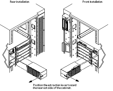
Figure 7-6 PCM -- Front and Rear Installation

-
Use the printdiag (1M) command to determine if precharge current is present.
-
Use a Phillips #1 screwdriver to turn each quarter-turn access slot on the power supply to the unlocked position (Figure 7-7).
Figure 7-7 Quarter-Turn Access Slots

-
Pull the end of the extraction lever outward to release the power supply from the centerplane.
-
Pull out the power supply.
You will see a message similar to the following example on your system console:
NOTICE: Core Power Supply 2 Removed
-
Insert the replacement power supply halfway into the guide slots, then:
-
Verify that power supply is oriented so that the extraction lever is toward the outside edge of the system (Figure 7-6).
-
Verify that the arrows in the quarter-turn access slots are turned to the unlocked position.
-
Open the extraction lever to the unlocked position.
The power supply will not seat fully unless the extraction lever is in the unlocked position.
 Caution -
 DO NOT FORCE the power supply into a slot; this can cause damage to the power supply and system.
The power supply should insert and seat smoothly. If it binds, remove it, and inspect the slot for obstructions. Take care to avoid damaging the springfingers at the bottom of the power supply.
-
-
Slide the power supply to the centerplane, then use the extraction lever to seat the power supply.
Swing the lever inward to the locked position. Do not press on the front panel of the power supply to seat it; doing so will damage the connector pins.
-
Use a Phillips #1 screwdriver to turn each quarter-turn access slot to the locked position (Figure 7-7).
-
Check to be sure the green LED is lit.
If the green LED is not lit, the power supply is not seated properly. Repeat Step 2 to Step 8. If the green LED is still not lit, see Chapter 10, Flow Diagrams for Troubleshooting for more information.
When the power supply is correctly installed, you will see a message similar to the following example on your system console:
NOTICE: Core Power Supply 2 Installed
NOTICE: Core Power Supply 2 OK
NOTICE: Redundant power available
- © 2010, Oracle Corporation and/or its affiliates
