Centerplane Connector
Note -
Information for the CPU/Memory+ board centerplane connector also applies to the I/O+ and Disk board centerplane connectors.
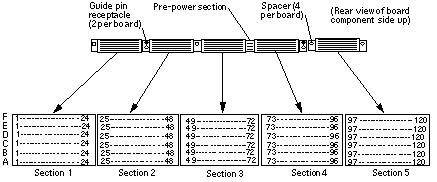
The CPU/Memory+ board centerplane connector is mounted on the rear of the board, opposite the side of the board with the LED display and extraction levers. See Figure G-2. The connector is comprised of modular sections, each with its own set of receptacle pins. See Figure G-3.
Figure G-2 CPU/Memory+ Board Centerplane Connector Location

Figure G-3 Centerplane Connector Detail

A three-bladed power section results in 12 pins on the board. There are six, 120-pin rows, labeled A through F, spread across the remaining five sections; each section has 24 pins of each 120-pin row.
- © 2010, Oracle Corporation and/or its affiliates
