Powering On the System
Note -
It is advisable to connect an ASCII terminal to the system during installation. See "Connecting an ASCII Terminal", for terminal settings and connections. Observe the yellow (middle) LED on the front panel. It should go off when the boot process completes. If it remains lit, observe the terminal screen for boot messages produced by the firmware diagnostic program during power on.
To power on the cabinet system:
-
Begin with a safety inspection of the system:
-
Turn the system key switch to
 (the Standby position).
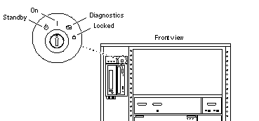
See Figure 3-1.
Note -The standby position (
 ) does not turn off any AC-powered drive trays in the lower part of the system cabinet. The key switch controls only the DC power supply and DC-powered devices in the main cabinet.
-
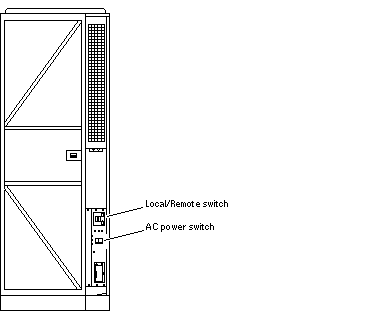
Turn the AC power sequencer power switch (Figure 3-2) to Off.
The AC power sequencer is at the rear of the cabinet.
-
Verify that the cabinet AC power cord is plugged into a wall socket.
Figure 3-1 Key Switch on the Enterprise 6500/5500
 Table 3-1 Key Switch Positions
Position
Function
Standby
Off, no DC power
On
Normal power on
Diagnostics
Normal power on, with full diagnostics
Locked
Normal power on, in secure mode
 Caution -
 The outlet must be a 200-240 VAC 30A circuit intended solely for use by the server cabinet. The electrical receptacles must be grounded, and the grounding conductors serving these receptacles must be connected to the earth ground at the service equipment.
 Caution -
 Do not disconnect the AC power cord from the wall socket when you work on or in the server cabinet. This connection provides a ground path that prevents damage from electrostatic discharge.
 Caution -
 Never move the system or expansion cabinets when system power is on. Excessive movement can cause catastrophic disk drive failure. Always power the system OFF before moving it.
-
-
Turn on power to any expansion cabinets.
Read the documentation supplied with each type of expansion cabinet for specific instructions.
Figure 3-2 Switches on the AC Power Sequencer

-
Turn on power to the terminal (if applicable).
-
Set the system cabinet Local/Remote switch (Figure 3-2) to Local.
-
Turn the AC power switch (Figure 3-2) to On.
Listen for the sound of AC-powered devices such as disk drives and fans in the disk drive tray(s).
Note -The front panel keys for this switch are packed in the accessory box.
-
Turn the key switch to the On position.
The system will run firmware diagnostics for about one minute and then boot.
You should see and hear several things happen:
-
The fans in the power supplies begin turning.
-
The left LED (green) on the front of the cabinet turns on immediately to indicate the DC power supply is functioning.
-
The middle LED (yellow) begins flashing.
-
The right LED (green) flashes after firmware completes to denote that the operating system is running.
-
The terminal screen lights up upon completion of the internal self-test.
-
-
Watch the terminal screen for any firmware error messages.
Note -If the middle front panel LED remains lit after the system has booted, firmware has found (and deconfigured) failing hardware in the main cabinet.
POST (power-on-self-test) tests subassemblies and some interface paths between subassemblies.
At the conclusion of testing, firmware automatically attempts to reconfigure the system, omitting any parts of the system that have failed diagnostics.
If there are no faults, or if firmware completes a successful reconfiguration in response to detected faults, the system boots.
If the system is unable to communicate with the network, see "Failure of Network Communications".
Note -POST does not test drives or internal parts of SBus cards. To test these devices, run OpenBoot PROM (OBP) diagnostics manually after the system has booted. Refer to the OpenBoot Command Reference for instructions.
Note -If faulty parts are detected and configured out of the working system, you and the system manager must decide whether to operate the system until replacement parts arrive, or to halt operation. Also, if a faulty component cannot be replaced in the field, the entire subassembly (like the system board) must be replaced.
-
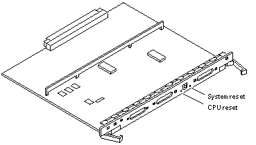
To restart firmware, or if the system hangs, press the CPU reset switch on the clock+ board (Figure 3-3).
Figure 3-3 Reset Switches on the Clock+ Board

- © 2010, Oracle Corporation and/or its affiliates
