Key Switch Assembly
Removing the Key Switch Assembly
-
Power off the Enterprise system.
See the power off instructions in Chapter 11, Powering Off and On .
-
Remove the key from the key switch.
-
Remove the top front panel by grasping the bezel on both sides and pulling the bezel away from the ball studs (Figure 12-1).
-
Remove the left side panel.
See Chapter 12, Preparing for Service, for instructions.
-
Disconnect the power and data cable assemblies from the back of the media tray.
-
Remove the two screws that attach the media tray to the flange on the side of the fan tray shelf (Figure E-7).
-
Disconnect the power cable from the fan in the media tray.
-
Disconnect the keyswitch cable.
-
Loosen and remove the tie wrap from fan cable.
-
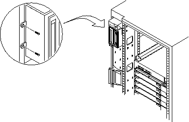
Remove the two screws (Figure E-8) that hold the media tray.
-
Remove the media tray and set it aside.
Figure E-7 Removing the Two Screws that Attach the media tray to the Flange
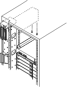
Figure E-8 Removing the Two Screws that Attach the media tray to the Cabinet Pillar
-
Disconnect the cable from the back of the key switch assembly.
-
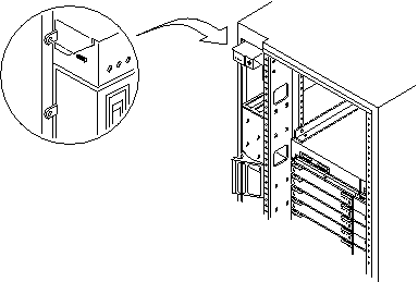
Remove the screw on the left side that attaches the key switch assembly to the cabinet pillar (Figure E-9).
Figure E-9 Removing the Screw from the Left Pillar
-
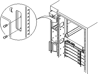
Remove the two screws on the right side that attach the key switch assembly to the cabinet pillar.
You can access the two screws through the space previously occupied by the media tray (Figure E-10).
Figure E-10 Removing the Two Screws from the Right Pillar
-
Carefully remove the key switch assembly from the cabinet.
Pull out the right side first and gently rock the assembly until the left flange clears the cabinet (Figure E-11).
Figure E-11 Replacing the Key Switch Assembly in the Enterprise 6500/5500 Systems
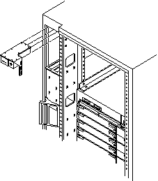
Replacing the Key Switch Assembly
-
Insert the key switch assembly into the cabinet until it is seated properly.
The key switch assembly is seated properly when the screw holes align with the cabinet pillar (Figure E-11).
-
Replace the two screws on the right side that attach the key switch assembly to the cabinet pillar.
You can access the two screws through the space previously occupied by the media tray (Figure E-10).
-
Replace the screw on the left side that attaches the key switch assembly to the cabinet pillar (Figure E-9).
-
Connect the key switch cable assembly into the back of the key switch assembly.
-
Replace the media tray into the cabinet using the support system cabinet CD shelf as a guide.
When seated properly, the media tray is flush with the key switch assembly in the cabinet.
-
Replace the two screws that attach the media tray to the cabinet pillar (Figure E-8).
-
Replace the two screws that attach the media tray to the flange on the bottom of the fan tray shelf (Figure E-7).
-
Connect the media tray power and data cable assemblies into the back of the media tray.
-
Replace the fan tray shelf cover.
Replace the 10 screws and attach the cover to the cabinet.
-
Replace the side panel closest to the key switch assembly.
See Chapter 12, Preparing for Service, for information on replacing the side panel.
-
Power on the Enterprise system.
See the power on instructions in Chapter 11, Powering Off and On .
- © 2010, Oracle Corporation and/or its affiliates
