Installing a Board
Board Slot Selection
Note -
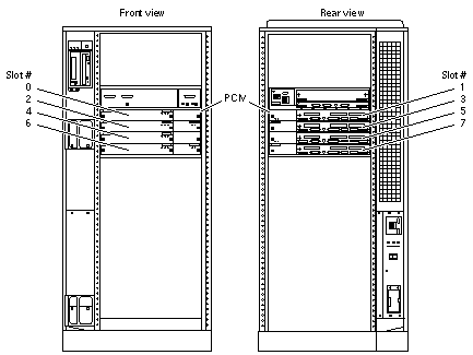
Logically there is no difference between the board slots in the front or rear of the card cage, and each slot can accept any board type. It is suggested that CPU/Memory+ boards be installed in the front slots, and I/O+ and Disk boards be installed in the rear slots because of cabling. Should the need arise, however, any of these three board types can be placed in any of the numbered board slots, with these exceptions: Slot 1: Slot 1 should be used by the first I/O+ board because it is the only slot connected to the onboard SCSI devices. Slots 14 and 15: In Enterprise 6500 systems, Disk boards are supported only in these two slots.
The first CPU/Memory+ board is placed in slot 0, followed sequentially by all remaining even numbered slots. If there are boards remaining, they can be installed sequentially in odd numbered slots, if available, in the system rear (with the exception of slot 1 as noted above). See Figure 5-6.
Other than the slot 1 exception, a Disk board can be placed in any of the numbered board slots in Enterprise 5500/4500 systems. Use only slot 14 and slot 15 in Enterprise 6500 systems, and you must use slot 15 if only one Disk board is installed.
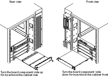
For boards being placed in the rear of the system, ensure that the component side is up. If the boards are placed in the front of the system, ensure that the component side is down (Figure 5-7).
Figure 5-6 Enterprise 5500/4500 Board Locations

Cooling and Power Issues
There should be one power/cooling module (PCM) for every two boards to adhere to cooling and power requirements. The PCMs must be installed adjacent to populated board slots to ensure the fan in the PCM can cool the respective boards.
Note -
All empty board slots in Enterprise 4500 or 5500 systems must have a filler panel installed to ensure proper cooling. All empty slots in Enterprise 6500 systems must have load boards installed.
Inserting a System Board
-
Carefully insert the board (component side down if in front; component side up if in the rear) in the proper slot in the card cage, ensuring that the board does not slip out of the left and right card guides (Figure 5-7).
Figure 5-7 Board Replacement

-
Ensure that both extraction levers are in the insert position (arrow pointing outward) and that the quarter-turn access slots are unlocked (arrow indicates unlocked position) as you slide the board toward the centerplane receptacles.
See Figure 5-4 and Figure 5-5. The board will not seat fully unless the levers are in this starting position and both quarter-turn access slots are unlocked.
 Caution -
 DO NOT FORCE any board into a slot; this can cause damage to the board and system. The board should insert and seat smoothly. If it binds, remove the board and inspect the card cage slot for any obvious obstructions. Also inspect both the board and the centerplane for bent pins or other damage.
-
Push the board into the card cage, then simultaneously press both extraction levers to seat the board on the centerplane.
Pushing both levers simultaneously avoids twisting the board and bending the connector pins, and mates the board centerplane connector to the matching receptacle on the centerplane. Do not press on board front panel to seat it--doing so will damage the connector pins.
-
Mechanically lock the board to the system chassis by inserting a Phillips #1 screwdriver into each quarter-turn access slot and then turning to the locked position.
See Figure 5-4.
-
Connect the Disk board to a SCSI Host Adapter (on-board or SBus card).
The Disk board kit includes an 80-cm fast-wide SCSI cable. If the Disk board is installed on the opposite side of the card cage from the SCSI Host Adapter, you must use a 2-meter cable, part number 530-1885 (sold separately).
-
If the Disk board is the last (or only) board in the SCSI chain, terminate the SCSI out connector on the disk board.
The Disk board kit includes a fast-wide SCSI terminator, part number 150-2267.
-
Replace or connect all other necessary cables to the fronts of the boards.
-
Once the Disk board has been installed, a message similar to the following will be displayed on the monitor (if the system is powered on):
Example depicts screen output when a new Disk board has been hot-plugged into slot 6 of an operating Enterprise system:
NOTICE: Disk Board Hotplugged into Slot 6
NOTICE: Board 6 is ready to remove
This screen output indicates that the board has been detected by the system and is in the low power mode. Additionally, any subsequent prtdiag(1M) output would include information for board slot 6. Again, note that the system will not use the new board until the system is rebooted.
-
Reboot the system now or schedule a later time to reboot when system disruption will be minimized.
Cabling Issues for Enterprise 6500 Systems
Slot 15 installation
-
Use an 80-cm SCSI cable to connect the Disk board to the SCSI Host Adapter (onboard or SBus card).
-
Install a SCSI terminator on the disk board if it is the last (or only) board in the SCSI chain.
Slot 14 installation
-
Connect the Disk board to the SCSI Host Adapter (onboard or SBus card):
-
If an I/O+ board is installed in the front, use an 80-cm SCSI cable to connect the Disk board to the SCSI Host Adapter.
-
If all I/O+ boards are installed in the rear, use a 2-meter SCSI cable (sold separately) to connect the Disk board to the SCSI Host Adapter. Route the cable down the side of the card cage, through the cable pass in the cabinet.
-
-
Install a SCSI terminator on the disk board if it is the last (or only) board in the SCSI chain.
- © 2010, Oracle Corporation and/or its affiliates
