Usage of Sun Management Center 3.5 Software on Sun Enterprise 6500/5500/4500/3500 Systems
|
This supplement covers the following topics:
Applicable Platforms
This book provides platform-specific Sun Management Center software information for the following Sun Enterprise
 platforms:
- Sun Enterprise 6500 server
- Sun Enterprise 5500 server
- Sun Enterprise 4500 server
- Sun Enterprise 3500 server
The Sun Management Center 3.5 User's Guide describes the software functionality that is common to all the supported hardware platforms, while platform-specific information is included in this supplement.
For complete information on how you can use the Sun Management Center software to manage and monitor your machines, read both this supplement and the Sun Management Center 3.5 User's Guide.
Dynamic Reconfiguration
|
Note - In this supplement, the dynamic reconfiguration features that are described are applicable only to the Sun Enterprise 6500/5500/4500/3500 systems using the 12/02 release or subsequent compatible version of the Solaris 9 Operating Environment. 9 Operating Environment.
|
Dynamic reconfiguration enables you to add, remove, or replace hardware units such as CPU/Memory and I/O boards while the system is powered up and running. Dynamic reconfiguration also enables boards to be reserved in a powered up state and inactive state for immediate use as spare units. This feature is only available on systems that have boards and slots designed for hot-plugging.
|
Note - The Dynamic Reconfiguration module must be loaded to use the dynamic reconfiguration feature of the Sun Management Center software. For more information on loading modules, refer to the "Managing Modules" chapter in the Sun Management Center 3.5 User's Guide.
|
|
 To Display the Dynamic Reconfiguration Table To Display the Dynamic Reconfiguration Table
|
To display the Dynamic Reconfiguration Table, do one of the following:
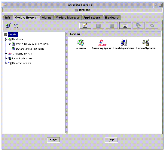
- Bring up the platform Details window under the Browser tab and Hardware icon. FIGURE 2-1 shows the icon for the Dynamic Reconfiguration module.
FIGURE 2-1 Dynamic Reconfiguration Module
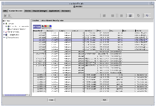
- Double-click on Dynamic Reconfiguration, and the Dynamic Reconfiguration table shown in FIGURE 2-2 appears.
FIGURE 2-2 Dynamic Reconfiguration Table
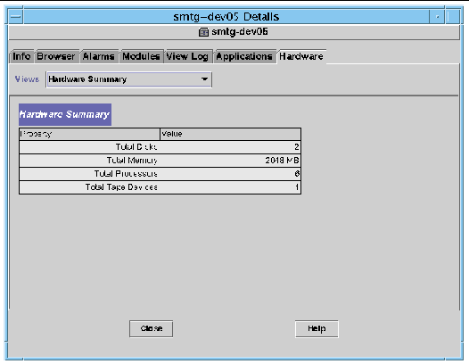
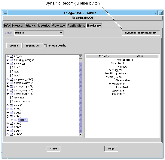
- The Dynamic Reconfiguration button is displayed also in the physical and logical views of the Hardware tab of the Details window. However, by default the Hardware tab displays the Hardware Summary view (FIGURE 2-3), which does not have the Dynamic Reconfiguration button.
FIGURE 2-3 Hardware Tab (Default View)
To display the dynamic reconfiguration table:
a. Open the Views pull-down menu (FIGURE 2-4) and select one of the system views.
Depending on your selection, you see either a physical view of the system (FIGURE 2-5) or a logical view (FIGURE 2-6). Both views have a Dynamic Reconfiguration button.
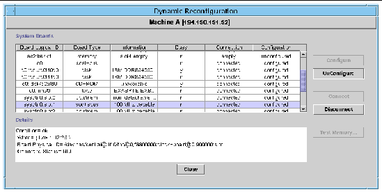
b. Click the Dynamic Reconfiguration button to see the Dynamic Reconfiguration window (FIGURE 2-7).
FIGURE 2-4 Pull-Down Menu in the Hardware Tab
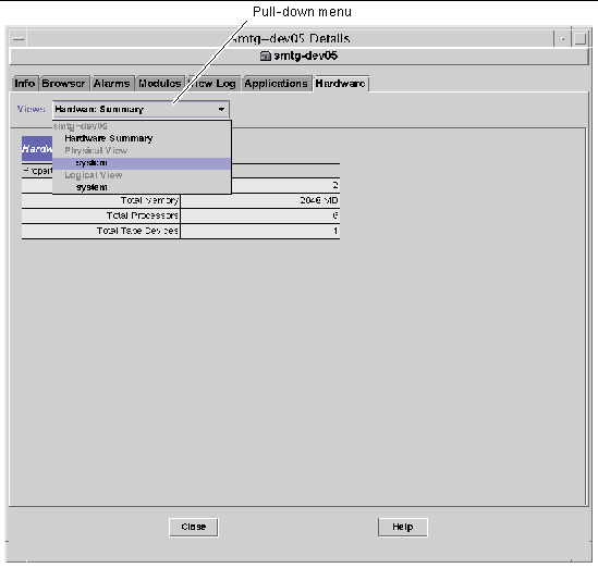
FIGURE 2-5 Physical View in the Hardware Tab
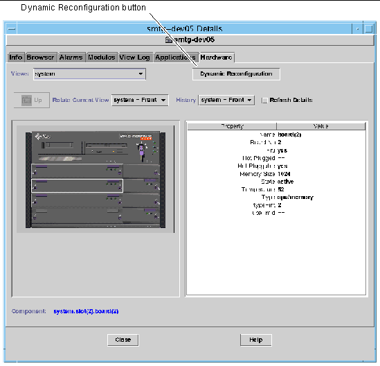
FIGURE 2-6 Logical View in the Hardware Tab
|
Note - For more information on the Hardware tab of the Details window, refer to the "Details" chapter in the Sun Management Center 3.5 User's Guide.
|
FIGURE 2-7 Dynamic Reconfiguration Window
Dynamic Reconfiguration Data Properties Table
The following table provides a brief description of the data properties for the Dynamic Reconfiguration module. When selected, the dynamic reconfiguration data property table is displayed in the Browser tab of the Details window. For more information on viewing data property tables, refer to the "Browser" chapter in the Sun Management Center 3.5 User's Guide.
TABLE 2-1 Dynamic Reconfiguration Properties
|
Property
|
Description
|
|
Unique Ap_Id
|
Unique attachment point ID
|
|
Receptacle
|
An attachment point defines two unique elements, which are distinct from the hardware resources that exist beyond the attachment point. One of the two elements of an attachment point is a receptacle. Configuration administration supports physical insertion and removal operations as well as other configuration administration functions at an attachment point.
|
|
Occupant
|
The other element of the attachment is an occupant physical insertion or removal of hardware resources. This occurs at attachment points and results in a receptacle gaining or losing an occupant.
|
|
Condition
|
Condition or status
|
|
Information
|
Additional information about the attachment point, including the date of operation
|
|
When
|
Date and time of the last requested action
|
|
Type
|
Type affected: CPU, disk, memory, or other if known
|
|
Busy
|
State: whether busy or not
|
|
Phys_Id
|
Directory path or physical address
|
System Boards Summary Table
Where applicable, the system boards summary table lists all slots in the card cage and shows the status of all slots and their occupants (TABLE 2-2).
TABLE 2-2 Columns in the System Boards Summary Table
|
Column
|
Description
|
|
Board Logical ID
|
Board ID as reflected by the cfgadm command
|
|
Board Type
|
Type of board (I/O, CPU/memory, or unknown)
|
|
Information
|
When the board was installed in the slot and additional information about the board, including whether or not it is detachable
|
|
Busy
|
Whether the board is currently in use (yes or no)
|
|
Connection
|
Whether the board is connected, disconnected, or the board slot is empty
|
|
Configuration
|
Whether the board is configured or unconfigured
|
Details Panel
Below the system boards summary table, the Details panel shows information about the state of a selected slot and its occupant board (TABLE 2-3).
TABLE 2-3 Details Panel in the Dynamic Reconfiguration Window
|
Field
|
Description
|
|
Condition
|
Status of the board occupying that slot
|
|
When
|
Date and time of the last requested action. When you select a new action, the values change to the current date and time.
|
|
Board Physical ID
|
System designation for the board
|
|
Command Status
|
Reports dynamic reconfiguration operations and error conditions
|
|
Note - The Configure, Unconfigure, Connect, Disconnect, and Test Memory buttons are grayed out as required by the condition of the board and slot. You cannot perform any dynamic reconfiguration when the slot is empty.
|
Performing Dynamic Reconfiguration Operations
You can perform three types of operations in the Dynamic Reconfiguration window:
- Connecting or disconnecting a board
- Configuring or unconfiguring a board or memory bank
- Testing memory
|
Note - For information on the proper use of these functions, refer to the Sun Enterprise 6x00, 5x00, 4x00, and 3x00 Systems Dynamic Reconfiguration User's Guide, part number 806-3984.
|
If after performing a dynamic reconfiguration operation, you see the error messages Error opening logical view or Error opening physical view, close and reopen the Details window for the host.
|
 To Connect a Board To Connect a Board
|
|
Note - Refer to the "Procedures" chapter in the Sun Enterprise 6x00, 5x00, 4x00, and 3x00 Systems Dynamic Reconfiguration User's Guide, part number 806-3984, for the step-by-step instructions for this procedure.
|
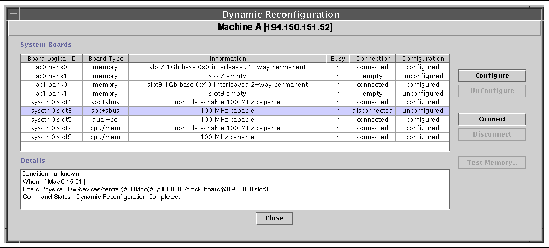
 Select the board row in the system boards summary table and click the Connect button (FIGURE 2-8).
FIGURE 2-8 Dynamic Reconfiguration Window With Disconnected Board Selected
|
 To Disconnect a Board To Disconnect a Board
|
|
Note - Refer to the "Procedures" chapter in the Sun Enterprise 6x00, 5x00, 4x00, and 3x00 Systems Dynamic Reconfiguration User's Guide, part number 806-3984, for the step-by-step instructions for this procedure.
|
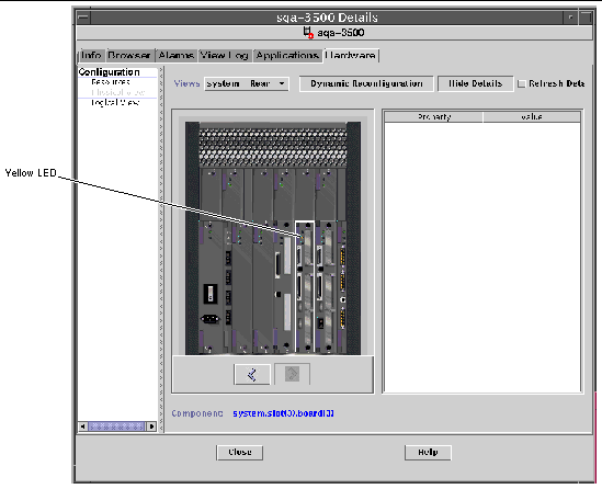
 Select the board row in the system boards summary table and click the Disconnect button.
The disconnected board displays a yellow LED (FIGURE 2-9).
If you disconnect a connected and configured board, the board is disconnected and also automatically unconfigured, thus performing two operations at once.
FIGURE 2-9 Physical View of a Disconnected Board With Yellow LED
|
 To Configure a Board To Configure a Board
|
|
Note - Refer to the "Procedures" chapter in the Sun Enterprise 6x00, 5x00, 4x00, and 3x00 Systems Dynamic Reconfiguration User's Guide, part number 806-3984, for the step-by-step instructions for this procedure.
|
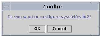
1. Select the board row in the system boards summary table and click the Configure button.
The Confirm dialog box is displayed (FIGURE 2-10).
2. Select OK or Cancel.
When you configure a disconnected board, the board is also automatically connected, thus performing two operations at once.
FIGURE 2-10 Confirm Dialog Box
|
 To Unconfigure a Board To Unconfigure a Board
|
|
Note - Refer to the "Procedures" chapter in the Sun Enterprise 6x00, 5x00, 4x00, and 3x00 Systems Dynamic Reconfiguration User's Guide, part number 806-3984, for the step-by-step instructions for this procedure.
|
 Select the board row in the system boards summary table and click the Unconfigure button.
Testing Memory
Sun Management Center 3.5 software enables you to test the memory of
CPU/Memory boards in the Dynamic Reconfiguration window.
|
 To Test Memory To Test Memory
|
|
Note - Refer to the "Procedures" chapter in the Sun Enterprise 6x00, 5x00, 4x00, and 3x00 Systems Dynamic Reconfiguration User's Guide, part number 806-3984, for the step-by-step instructions for this procedure.
|
A board must be unconfigured before its memory can be tested.
1. Select the board row in the system boards summary table and click the Test Memory button.
The Test Memory dialog box is displayed (FIGURE 2-11).
FIGURE 2-11 Test Memory Dialog Box
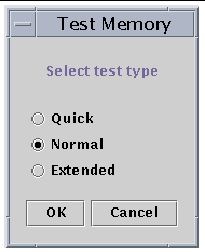
2. Select the type of test: Quick, Normal, or Extended.
Quick and normal tests take several minutes, while an extended test may take more than an hour. For more information on these tests, refer to the Sun Enterprise 6x00, 5x00, 4x00, and 3x00 Systems Dynamic Reconfiguration User's Guide, part number 806-3984.
3. Click OK to close this dialog box and test the memory, or click Cancel to cancel your request.
Config-Reader Module
The Config-Reader module, when loaded, is displayed under the hardware icon.
The Config-Reader (sun4u/sun4d) module monitors your hardware and alerts you whenever there is a problem. For example, this module checks for single in-line memory module (SIMM) errors, monitors board temperatures and power supply status, and so on.
This module also obtains the physical view and logical view of your host. For more information on the physical and logical views, refer to the Sun Management Center 3.5 User's Guide.
Config-Reader Module Data Property Tables
This section includes the Config-Reader module data property tables:
The following tables describe the data properties that are contained in each of the Config-Reader data property tables. When selected, the Config-Reader data property tables are displayed in the Browser tab of the Details window. For more information, see the "Browser" chapter in the Sun Management Center 3.5 User's Guide.
System Table
TABLE 2-4 System Properties
|
Property
|
Description
|
|
Name
|
Instance name
|
|
Operating System
|
Operating environment running in the machine
|
|
Operating System Version
|
Operating environment version
|
|
System Clock Frequency
|
Clock frequency
|
|
Architecture
|
Architecture of the machine
|
|
Host name of the System
|
Host name of the system
|
|
Machine Name
|
Machine type
|
|
System Platform
|
Hardware platform of the system
|
|
Serial Number
|
Serial number of the machine
|
|
Timestamp
|
Time stamp value
|
|
Raw Timestamp
|
Raw time stamp value
|
|
Total Disks
|
Total number of disks present in the system
|
|
Total Memory
|
Total memory present in the system
|
|
Total Processors
|
Total processors present in the system
|
|
Total Tape Devices
|
Total tape devices present in the system
|
Board Table
TABLE 2-5 Board Properties
|
Property
|
Description
|
|
Name
|
Instance name
|
|
Board No.
|
Number of the board
|
|
Fru
|
Field-replaceable unit
|
|
Hot Plugged
|
Whether it is hot-plugged
|
|
Hot Pluggable
|
Whether it is hot-pluggable
|
|
Memory size
|
Size of the memory
|
|
State
|
State
|
|
Temperature
|
Temperature of the board
|
|
Type
|
Type of board (for example, CPU/memory, SBus, clock, and so on)
|
CPU Unit Properties Table
TABLE 2-6 CPU Unit Properties
|
Property
|
Description
|
|
Name
|
Name
|
|
Board No.
|
Number of the board
|
|
Clock Frequency
|
Frequency of timer
|
|
Cpu Type
|
Type of system
|
|
Dcache Size
|
Size of Dcache in Kbytes
|
|
Ecache Size
|
Size of Ecache in Mbytes
|
|
Fru
|
Field-replaceable unit
|
|
Icache Size
|
Size of Icache in Kbytes
|
|
Model
|
Name of CPU model
|
|
Processor ID
|
Identification number of the processor
|
|
Status
|
Status of CPU unit
|
|
Unit
|
Identification of the unit
|
SIMM Table
TABLE 2-7 SIMM Properties
|
Property
|
Description
|
|
Name
|
Name of the SIMM
|
|
Board Reference Number
|
Number that references the board
|
|
Fru
|
Field-replaceable unit
|
|
Size
|
Size of SIMM in Mbytes
|
|
Slot
|
Number of the SIMM
|
|
Status
|
Status of the SIMM
|
AC Power Supply Table
TABLE 2-8 AC Power Supply Properties
|
Property
|
Description
|
|
Name
|
Name
|
|
Status
|
Status
|
Hot-Plug Charges Table
TABLE 2-9 Hot-Plug Properties
|
Property
|
Description
|
|
Name
|
Name
|
|
Fru
|
Field-replaceable unit
|
Auxiliary 5V Table
TABLE 2-10 Auxiliary 5V Properties
|
Property
|
Description
|
|
Name
|
Name
|
|
Fru
|
Field-replaceable unit
|
|
Status
|
Status
|
Peripheral 5V, Peripheral 12V, System 3V, and System 5V Table
TABLE 2-11 presents the properties for the following:
- Peripheral 5V
- Peripheral 5V Precharge
- Peripheral 12V
- Peripheral 12V Precharge
- System 3V
- System 3V Precharge
- System 5V
- System 5V Precharge
TABLE 2-11 Common Peripheral and System Properties
|
Property
|
Description
|
|
Name
|
Name
|
|
Fru
|
Field-replaceable unit
|
|
Status
|
Status of the power supply
|
Keyswitch Table
TABLE 2-12 Keyswitch Properties
|
Property
|
Description
|
|
Name
|
Name
|
|
Position
|
Position of the keyswitch
|
Peripheral Power Supply Table
TABLE 2-13 Peripheral Power Supply Properties
|
Property
|
Description
|
|
Name
|
Name
|
|
Fru
|
Field-replaceable unit
|
|
Hpu
|
Hot-pluggable unit
|
|
Status
|
Status of the peripheral power supply
|
|
Unit No.
|
Unit number
|
Power Supply Table
TABLE 2-14 Power Supply Properties
|
Property
|
Description
|
|
Name
|
Name
|
|
Fru
|
Field-replaceable unit
|
|
Hpu
|
Hot-pluggable unit
|
|
Status
|
Status
|
|
Unit No.
|
Unit number
|
Rack Fan Table
TABLE 2-15 Fan Properties
|
Property
|
Description
|
|
Name
|
Name, for example, rack_fan
|
|
Status
|
Status of the fan
|
Remote Console Table
TABLE 2-16 Remote Console Properties
|
Property
|
Description
|
|
Name
|
Instance name: for example, remote_console
|
|
Status
|
Status of the remote console: enabled or disabled
|
FHC Table
The FHC node is inside the I/O unit.
TABLE 2-17 FHC Properties
|
Property
|
Description
|
|
Name
|
Name
|
|
Board Num
|
Board number
|
|
Model
|
Name of the FHC model
|
|
Upa Mid
|
Number of the ultra port architecture unit
|
|
Version No.
|
Version number
|
AC Table
TABLE 2-18 AC Properties
|
Property
|
Description
|
|
Name
|
Name
|
|
Bank0 Status
|
Bank0 status
|
|
Bank1 Status
|
Bank1 status
|
|
Device Type
|
Device type
|
|
Model
|
Name of the AC model
|
|
Version No.
|
Version number
|
Fan Table
TABLE 2-19 Fan Properties
|
Property
|
Description
|
|
Name
|
Name
|
|
Status
|
Status of the fan
|
PFA Rules Table
TABLE 2-20 lists the properties for the Predictive Failure Analysis (PFA) rules.
TABLE 2-20 PFA Rules Properties
|
Property
|
Description
|
|
PFA SIMM Rule
|
SIMM rule value
|
|
PFA Disk Rule
|
Disk rule value
|
|
Smart/PFA Disk Rule
|
Smart PFA disk rule value
|
I/O Controllers Table
TABLE 2-21 I/O Controllers Properties
|
Property
|
Description
|
|
Name
|
Name
|
|
Board Number
|
Board number
|
|
Clock Frequency
|
Frequency of timer
|
|
Device Type
|
Device type
|
|
Instance Number
|
Instance Number
|
|
Model
|
Name of the I/O controller model
|
|
Reg
|
Reg property
|
|
UPA Mid
|
UPA MID
|
|
UPA Portid
|
UPA Port ID
|
|
Version Number
|
Version number
|
I/O Devices Table
TABLE 2-22 I/O Devices Properties
|
Property
|
Description
|
|
Name
|
Name instance
|
|
Device Type
|
Device type
|
|
Disk Count
|
Number of disks present on this device
|
|
Instance Number
|
Instance number
|
|
Model
|
Name of the I/O device model
|
|
Network Count
|
Number of network interfaces present on this device
|
|
Reg
|
Reg property
|
|
Tape Count
|
Number of tape devices present on this I/O device
|
Disk Device Table
TABLE 2-23 Disk Device Properties
|
Property
|
Description
|
|
Name
|
Name
|
|
Device Type
|
Device type
|
|
Disk Name
|
Name of the disk
|
|
Fru
|
Field-replaceable unit
|
|
Instance Number
|
Instance number of the disk
|
|
Disk Target
|
Disk target number
|
Tape Device Table
TABLE 2-24 Tape Device Properties
|
Property
|
Description
|
|
Name
|
Name
|
|
Device Type
|
Device type
|
|
Fru
|
Field-replaceable unit
|
|
Instance Number
|
Instance number of the tape
|
|
Model
|
Name of the tape device model
|
|
Tape Name
|
Tape name
|
|
Status
|
Status of the tape device
|
|
Tape Target
|
Tape target number
|
Network Device Table
TABLE 2-25 Network Device Properties
|
Property
|
Description
|
|
Name
|
Name
|
|
Device Type
|
Device type
|
|
Ethernet Address
|
Ethernet address of the interface
|
|
Internet Address
|
Internet address of the interface
|
|
Interface Name
|
Name of the interface
|
|
Symbolic Name
|
Symbolic name of the interface
|
Config-Reader Rules
The following table includes Config-Reader rules with detailed explanation of those rules that have critical alarms.
TABLE 2-26 Config-Reader Rules
|
Rule ID
|
Description
|
Type of Alarm
|
|
rcr4u201
|
Precharge status rule
This alarm is generated when the status of the precharge voltages is not "OK."
|
Critical
|
|
rcr4u203
|
Power supply status rule
This alarm is generated when the status of the power supply is not "OK."
|
Critical
|
|
rcr4u204
|
Fan status rule
This alarm is generated when the fan status is not "OK."
|
Error
|
|
rcr4u205
|
Temperature rule
This rule is triggered when the temperature on the system boards goes beyond a threshold value. Depending on the board temperature, a critical or an alert alarm is generated.
|
Critical, Alert
|
|
rcr4u207
|
CPU unit status rule
When the CPUs are not "online" this rule is generated.
|
Critical
|
|
rcr4u208
|
ECC error logged in syslog
|
Warning alarm that is closed immediately
|
|
rcr4u209
|
SIMM error rule
|
Alert alarm that is closed immediately
|
|
rcr4u210
|
Hardware error
|
Alert alarm that is closed immediately
|
|
rcr4u211
|
Fatal error
|
Alert alarm that is closed immediately
|
|
rcr4u212
|
CPU detects ECC error on SIMM
|
Alert alarm that is closed immediately
|
|
rcr4u213
|
Hot-plug removed
|
Alert alarm that is closed immediately
|
|
rcr4u214
|
Power failing
|
Alert alarm that is closed immediately
|
|
rcr4u215
|
Hot-plugged
|
Alert alarm that is closed immediately
|
|
rcr4u216
|
CPU panic
|
Alert alarm that is closed immediately
|
|
rcr4u217
|
SCSI tape error
|
Alert alarm that is closed immediately
|
|
rcr4u218
|
AC status rule
This rule is generated when the AC status is not "OK."
|
Critical
|
|
rcr4u219
|
Disk removed
|
Alert alarm that is closed immediately
|
|
rcr4u220
|
Disk inserted
|
Alert alarm that is closed immediately
|
|
rcr4u221
|
Redundant power
|
Alert alarm that is closed immediately
|
|
rcr4u224
|
Hot-plug installed
|
Alert alarm that is closed immediately
|
|
rcr4u225
|
ST status rule
This rule is generated when the status of the tape drive is not "OK."
|
Critical
|
|
rpfa300
|
Complex rule looks for SIMM memory errors in syslog and makes a predictive failure alarm entry for each error.
|
Critical
|
|
rpfa301
|
Complex rule looks for disk soft errors in syslog and makes a predictive failure alarm entry for each error.
|
Critical
|
|
rpfa302
|
Complex rule looks for disk soft errors in syslog that are spilled out by a SMART drive.
|
Critical
|
 Management Center software information for the following Sun Enterprise
 platforms:


 Select the board row in the system boards summary table and click the Connect button (FIGURE 2-8).

 Select the board row in the system boards summary table and click the Disconnect button.


 Select the board row in the system boards summary table and click the Unconfigure button.
