| Sun Management Center 3.5 Version 6 Supplement for Sun Fire Midrange Systems
|
   
|
Platform and Domain Administration and Monitoring Using the Platform Agent
|
This chapter describes Platform Administration procedures and features for Sun Fire midrange systems.
The following topics are discussed:
Sun Fire Midrange Systems Platform Administration Module
For Sun Fire midrange systems, platform administration procedures use the Sun Fire Midrange Systems Platform Administration Module. This module is loaded under the Hardware category in the Module Browser tab of the Object Details window.
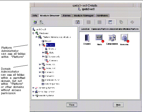
Only users with the correct access privileges can see the data in the corresponding views. For example, a user with access privileges for Platform and Domain A can view data only for Platform and Domain A, but not Domain B, Domain C, or Domain D. FIGURE 3-1 shows which tables a platform administrator can see and which tables a domain administrator can see.
FIGURE 3-1 Details Window for a Sun Fire Midrange Systems Platform Object
|
Note - In the examples that follow, the figures show only a Sun Fire midrange systems object. In an actual situation, other types of objects may be present.
|
 To Create a Sun Fire Midrange Systems Domain Object Only To Create a Sun Fire Midrange Systems Domain Object Only
|
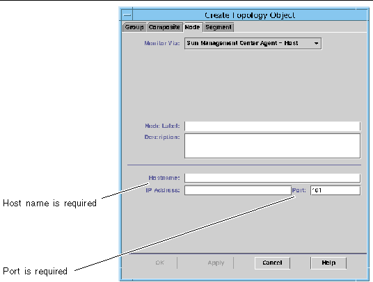
1. In the main console window menu bar, choose Edit > Create an Object.... > Node > Sun Management Center Agent - Host.
The system displays the Create Topology Object window. By default, the window opens to the Node tab and Sun Management Center Agent -Host (FIGURE 3-2).
2. Do the following:
a. Enter the label name for the object.
b. Enter the description of the object, if desired.
c. Enter the host name where the domain agent is running.
The host should be a Sun Fire midrange machine.
d. Enter the base agent port number.
The default base agent port number is 161.
3. Complete this procedure with one of the following actions:
- Click OK to accept the changes you have made and close this window.
- Click Apply to apply your changes without closing this window.
- Click Help to display the help page for this panel in the help browser.
- Click Cancel to cancel your request.
If an error occurs, an error message is displayed in the status message field.
|
Note - Clicking the Help button displays the help page corresponding to object creation in Sun Management Center software.
|
 To Create a Sun Fire Midrange Systems Platform Object Only To Create a Sun Fire Midrange Systems Platform Object Only
|
1. In the main console window menu bar, choose Edit > Create an Object.... > Node > Sun Management Center Agent - Platform.
The system displays the Create Topology Object window. By default, the window opens to the Node tab and Sun Management Center Agent -Host (FIGURE 3-2).
Change the object name to Sun Management Center Agent - Platform.
2. Do the following:
a. Enter the label name for the object.
b. Enter the description of the object, if desired.
c. Enter the host name where the platform agent is running.
The host can be any machine.
d. Enter port number 166.
3. Complete this procedure with one of the following actions:
- Click OK to accept the changes you have made and close this window.
- Click Apply to apply your changes without closing this window.
- Click Help to display the help page for this panel in the help browser.
- Click Cancel to cancel your request.
If an error occurs, an error message is displayed in the status message field.
|
Note - Clicking the Help button displays the help page corresponding to object creation in Sun Management Center software.
|
FIGURE 3-2 Node Tab in Create Object Window
 To Create a Sun Fire Midrange Systems Composite Object To Create a Sun Fire Midrange Systems Composite Object
|
Normally, a composite object includes a domain agent and a platform agent. This procedure describes how to create a composite object.
Sun Management Center 3.5 software does not support the creation of composite objects when the platform agent is running in a different domain than the system controller. This is because the SC firmware does not support domain name detection for Sun Management Center, since the SC can be configured with multiple IP/domain interfaces, and the SC firmware has no way to tell which domain Sun Management Center is monitoring.

|
Caution - If the platform agent and domain agent are running in different domains, the composite object is created without the domain agent, even though the domain agent is running. You can create a separate domain agent object by choosing Edit > Create an Object.... > Node > Agent-Host.
|
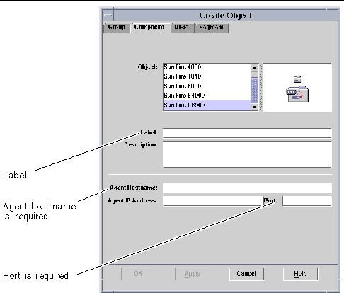
1. In the main console window menu bar, choose Edit > Create an Object.... > Composite > Sun Fire nnnn, where nnnn is the number of the Sun Fire midrange machine.
The system displays the Create Object window with the Composite tab (see FIGURE 3-3).
2. Do the following:
a. Enter the label name for the composite object
b. Enter the description of the composite object, if desired.
c. Enter the host name where the platform agent is running.
The host can be any machine.
d. Enter the base agent port number.
3. Complete this procedure with one of the following actions:
- Click OK to accept the changes you have made and close this window.
- Click Apply to apply your changes without closing this window.
- Click Help to display the help page for this panel in the help browser.
- Click Cancel to cancel your request.
If an error occurs, an error message is displayed in the status message field.
|
Note - Clicking the Help button displays the help page corresponding to object creation in Sun Management Center software.
|
FIGURE 3-3 Co mposite Tab With Sun Fire Midrange Systems
Accessing the Platform Tables in the Platform Administration Module
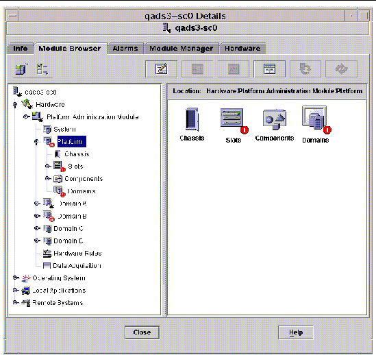
The platform administrator can view all the tables under the Platform Administration Module (FIGURE 3-4). The tables and their properties are summarized in this section.
FIGURE 3-4 Platform Tables
Platform System
TABLE 3-1 provides a brief description of the properties for Sun Fire midrange systems.
TABLE 3-1 Sun Fire Midrange Systems
|
Property
|
Rule (if any)
|
Description
|
|
Platform
|
|
Displays the description of platform, such as Sun-Fire-6800
|
Platform Chassis
TABLE 3-2 provides a brief description of the properties for a chassis on Sun Fire midrange systems.
TABLE 3-2 Platform Chassis
|
Property
|
Rule (if any)
|
Description
|
|
Chassis Description
|
|
Displays the description of the chassis
|
|
Chassis Fru Index
|
|
Displays the chassis field-replaceable unit (FRU) index
|
|
Chassis SC Name
|
|
Displays the SC host name on the chassis
|
|
Chassis Location
|
|
Displays the location of the chassis
|
|
Chassis Contact
|
|
Displays the name of the person who is responsible for this chassis
|
|
Chassis Log Host
|
rspa1006
|
Displays the name or IP address of the SNMP log host for the chassis
|
|
Chassis Trap Hosts
|
rspa1006
|
Displays names or IP addresses of the SNMP trap hosts for this chassis. Format is host[:port].
|
|
Chassis Slots
|
|
Displays the total number of slots on the chassis
|
|
Chassis CPU Slots
|
|
Displays the number of chassis slots used for CPU boards
|
|
Chassis IO Slots
|
|
Displays the number of chassis slots used for I/O boards
|
|
Chassis Uptime
|
|
Displays the time the chassis has been up in milliseconds (ms)
|
|
Chassis Model
|
|
Displays the chassis model, such as Sun Fire 6800
|
|
Chassis Domains
|
|
Displays the number of domains for which this chassis is available, such as 4
|
|
Chassis Partition Mode
|
|
Displays the chassis partition mode: SinglePartition or DualPartition
|
|
Chassis DomainA Ethernet Address
|
|
Displays the domain A Ethernet address
|
|
Chassis DomainB Ethernet Address
|
|
Displays the domain B Ethernet address
|
|
Chassis DomainC Ethernet Address
|
|
Displays the domain C Ethernet address
|
|
Chassis DomainD Ethernet Address
|
|
Displays the domain D Ethernet address
|
|
Chassis MasterSC Ethernet Address
|
|
Displays the main SC Ethernet address
|
|
Chassis SlaveSC Ethernet Address
|
|
Displays the spare SC Ethernet address
|
|
Chassis System Serial Number
|
|
Displays the serial number of the chassis
|
|
Node Name
|
|
Displays the Solaris Operating System node name
|
|
Machine
|
|
Displays the machine name of the chassis
|
|
Platform
|
|
Displays the platform name, such as Sun-Fire-6800
|
Platform Slot Tables
This section contains slot tables for the platform:
- Empty Slots
- CPU Boards
- I/O Boards
- L2 Repeaters
- Fan Trays
- Power Supply
- SC
- Unknown Boards
Platform - Empty Slots
TABLE 3-3 provides a brief description of the properties for empty slots on Sun Fire midrange systems.
TABLE 3-3 Platform - Empty Slots
|
Property
|
Rule (if any)
|
Description
|
|
Slot Name
|
|
Displays the names of empty slots, such as SB2, SB4
|
|
Slot Power Status
|
rspa1011
|
Displays the power status: PoweredOff or PoweredOn
|
|
Slot Board Type
|
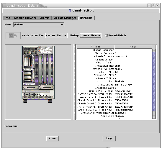
|
Displays the board type: Empty
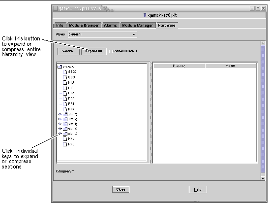
|
|
Slot State
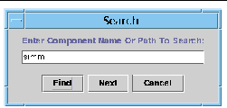
|
|
Displays the slot state: Active, Assigned, Available, or --, which means the board state does not apply to this slot
|
|
Slot Test Status
|
rspa1010
|
Displays the slot test status: Passed, NotTested, Unknown, Under Test, Start Test, Degraded, Failed, or Unusable
|
|
Slot Domain
|
|
Displays the domain to which the slot is assigned, such as Isolated or DomainA
|
|
Slot Status
|
rspa1000
|
Displays the slot status: OK, Failed, OverTemp, UnderTemp, or Unknown
|
Platform Slots - CPU Boards
TABLE 3-4 provides a brief description of the properties for CPU boards on Sun Fire midrange systems.
TABLE 3-4 Platform Slots - CPU Boards
|
Property
|
Rule (if any)
|
Description
|
|
CPU Board Name
|
|
Displays the identifier of the CPU board: SBx, where x is the slot number containing the CPU board
|
|
CPU Board Power Status
|
rspa1011
|
Displays the power status: PoweredOff or PoweredOn
|
|
CPU Board Type
|
|
Displays the CPU board revision number : CPU (default), CPU_V2, CPU_V3, or Unknown.
|
|
CPU Board Slot State
|
|
Displays the board slot state: Active, Assigned, Available, or --, which means the board state does not apply to this slot
|
|
CPU Board Test Status
|
rspa1010
|
Displays the board test status: Passed, NotTested, Unknown, Under Test, Start Test, Degraded, Failed, or Unusable
|
|
CPU Board Domain
|
|
Displays the domain to which the board is assigned, such as DomainA or DomainB
|
|
Slot Status
|
rspa1000
|
Displays the slot status: OK, Failed, OverTemp, UnderTemp, or Unknown
|
|
CPU Board Fru Index
|
|
Displays the field-replaceable unit (FRU) index for the CPU board
|
|
CPU Board Total CPU
|
|
Displays the total number of CPUs on this CPU board, such as 4
|
|
CPU Board Total Dram Memory (MB)
|
|
Displays the total amount of dynamic random access memory (DRAM) in megabytes (MB) on the CPU board, such as 4096
|
|
CPU Board Total Ecache Memory (MB)
|
|
Displays the total amount of external cache (Ecache) memory on the CPU board, such as 32
|
|
CPU Board Total WCI
|
|
Displays the total number of Sun Fire Link interfaces (WCIs) on the CPU board
|
|
CPU Board Temperature
|
|
Displays the CPU board temperature and range in the format: #ofTemp-Values|lower-limit:actual-temp-value:upper-limit:token|..|), where token is one of the following: normal, over-heat, under-heat, unknown. An example is 4|0:36:90:normal|0:37:9...
|
|
Is Cod Board?
|
|
States whether the CPU board is also a Capacity on Demand (COD) board or not (CodBoard or NonCodBoard)
|
Platform Slots - I/O Boards
TABLE 3-5 provides a brief description of the properties for I/O boards on Sun Fire midrange systems.
TABLE 3-5 Platform Slots - I/O Boards
|
Property
|
Rule (if any)
|
Description
|
|
IO Board Name
|
|
Displays the name of the I/O board: IBx, where x is the slot number containing the I/O board.
|
|
IO Board Power Status
|
rspa1011
|
Displays the power status: PoweredOff or PoweredOn
|
|
IO Board Type
|
|
Displays the board type: PCI, PCI+, CPCI, or WPCI
|
|
IO Board Slot State
|
|
Displays the board slot state: Active, Assigned, Available, or --, which means the board state does not apply to this slot
|
|
IO Board Test Status
|
rspa1010
|
Displays the board test status: Passed, NotTested, Unknown, Under Test, Start Test, Degraded, Failed, or Unusable
|
|
IO Board Domain
|
|
Displays the domain to which the board is assigned, such as DomainA or DomainB
|
|
Slot Status
|
rspa1000
|
Displays the slot status: OK, Failed, OverTemp, UnderTemp, or Unknown
|
|
IO Board Fru Index
|
|
Displays the field-replaceable unit (FRU) index for the I/O board
|
|
IO Board Total WCI
|
|
Displays the total number of Sun Fire Link interfaces (WCIs) on this board.
|
|
IO Board Total ParoliCpciDca
|
|
Displays the total number of parallel optical link (Paroli) cards, compact PCIs (CPCIs), and daughter card assemblies (DCAs) on this board.
|
|
IO Board Temperature
|
|
Displays the I/O board temperature and range in the format: #ofTemp-Values|lower-limit:actual-temp-value:upper-limit:token|..|), where token is one of the following: normal, over-heat, under-heat, unknown. An example is 2|0:30:90:normal|0:32...
|
Platform Slots - L2 Repeaters
TABLE 3-6 provides a brief description of the properties for L2 repeaters on Sun Fire midrange systems.
TABLE 3-6 Platform Slots - L2 Repeaters
|
Property
|
Rule (if any)
|
Description
|
|
L2 Repeater Name
|
|
Displays the L2 Repeater name: RPx, where x is the slot number containing the repeater
|
|
L2 Repeater Power Status
|
rspa1011
|
Displays the power status: PoweredOff or PoweredOn
|
|
L2 Repeater Board Type
|
|
Displays the board type: L2
|
|
L2 Repeater Slot State
|
|
Displays --, which means the board state does not apply to this slot
|
|
L2 Repeater Test Status
|
|
Displays the repeater test status: Passed or NotTested
|
|
L2 Repeater Domain
|
|
Displays Isolated, because an L2 repeater cannot be assigned to a domain
|
|
Slot Status
|
rspa1000
|
Displays the slot status: OK, Failed, OverTemp, UnderTemp, or Unknown
|
|
L2 Repeater Fru Index
|
|
Displays the field-replaceable unit (FRU) index for the L2 repeater
|
|
L2 Repeater Domains
|
|
Displays the domains to which the repeater is available, such as A,B
|
|
L2 Repeater Temperature
|
|
Displays the L2 repeater temperature and range in the format: #ofTemp-Values|lower-limit:actual-temp-value:upper-limit:token|..|), where token is one of the following: normal, over-heat, under-heat, unknown. An example is 2|0:28:90:normal|0:30:90...
|
Platform Slots - Fan Trays
TABLE 3-7 provides a brief description of the properties for fan trays on Sun Fire midrange systems.
TABLE 3-7 Platform Slots - Fan Trays
|
Property
|
Rule (if any)
|
Description
|
|
Fan Name
|
|
Displays the fan tray name: FTx, where x is the slot number containing the fan tray
|
|
Fan Power Status
|
rspa1011
|
Displays the power status: PoweredOff or PoweredOn
|
|
Fan Board Type
|
|
Displays the board type: Fan
|
|
Fan Slot State
|
|
Displays --, which means the board state does not apply to this slot
|
|
Fan Test Status
|
|
Displays the fan test status: Passed or NotTested
|
|
Fan Domain
|
|
Displays Isolated, because a fan tray cannot be assigned to a domain
|
|
Slot Status
|
rspa1000
|
Displays the slot status: OK, Failed, OverTemp, UnderTemp, or Unknown
|
|
Fan Fru Index
|
|
Displays the field-replaceable unit (FRU) index for the fan tray
|
|
Fan Speed
|
|
Displays the fan speed: Off, Low, or High
|
Platform Slots - Power Supply
TABLE 3-8 provides a brief description of the properties for power supplies on Sun Fire midrange systems.
TABLE 3-8 Platform Slots - Power Supply
|
Property
|
Rule (if any)
|
Description
|
|
Power Supply Name
|
|
Displays the power supply name: PSx, where x is the slot number containing the power supply
|
|
Power Supply Status
|
rspa1011
|
Displays the power status: PoweredOff or PoweredOn
|
|
Power Supply Board Type
|
|
Displays the board type: PowerSupply
|
|
Power Supply Slot State
|
|
Displays --, which means the board state does not apply to this slot
|
|
Power Supply Test Status
|
|
Displays the power supply test status: Passed or NotTested
|
|
Power Supply Domain
|
|
Displays Isolated, because a power supply cannot be assigned to a domain
|
|
Slot Status
|
rspa1000
|
Displays the slot status: OK, Failed, OverTemp, UnderTemp, or Unknown
|
|
Power Supply Fru Index
|
|
Displays the field-replaceable unit (FRU) index for the power supply
|
|
Power Supply Readings
|
|
Displays the power supply readings, such as 56.59|5.84|33.48
|
|
% Power Supply Used
|
|
Displays the percentage of the power supply that is used, such as 20, 17, 16, 37, or 42
|
|
Power Supply Low/High Input
|
|
Displays the power supply input as High or Low
|
|
Power Supply Primary Temperature
|
|
Displays the power supply primary temperature and range in the format: #ofTemp-Values|lower-limit:actual-temp-value:upper-limit:token|..|), where token is one of the following: normal, over-heat, under-heat, unknown. An example is 1|-1:23:78:normal|
|
Platform Slots - System Controller (SC)
TABLE 3-9 provides a brief description of the properties for an SC on Sun Fire midrange systems.
TABLE 3-9 Platform Slots - SC
|
Property
|
Rule (if any)
|
Description
|
|
SC Name
|
|
Displays the SC name: SSC0 or SSC1
|
|
SC Power Status
|
rspa1011
|
Displays the power status: PoweredOff or PoweredOn
|
|
SC Board Type
|
|
Displays the board type: SC, SC_V2, or Unknown
|
|
SC Slot State
|
|
Displays --, which means the board state does not apply to this slot.
|
|
SC Test Status
|
rspa1010
|
Displays the SC test status: Passed, Failed, OK, Under Test, NotTested, Degraded, or Unknown
|
|
SC Domain
|
|
Displays Isolated, because an SC cannot be assigned to a domain
|
|
Slot Status
|
rspa1000
|
Displays the slot status: OK, Failed, OverTemp, UnderTemp, or Unknown
|
|
SC Master Slave
|
rspa1004
|
Displays whether the SC is the main SC (Master) or the spare SC (Slave)
|
|
SC Fru Index
|
|
Displays the field-replaceable unit (FRU) index for the SC
|
|
SC Version
|
rspa1009
|
Displays the firmware version, such as 5.18.0; raises an alarm if less than 5.12.5
|
|
SC TimeZone
|
|
Displays the standard abbreviation for this SC's time zone, such as PST for Pacific Standard Time
|
|
SC Date
|
|
Displays current date and time for the SC
|
|
SC Network Configuration
|
|
Displays the network configuration, such as Fixed or Unknown
|
|
SC Hostname
|
|
Displays the host name of the SC
|
|
SC IP Address
|
rspa1005
|
Displays the IP address of the SC
|
|
SC Netmask
|
|
Displays the netmask for the SC
|
|
SC Default Routers
|
|
Displays the address of the default routers for the SC
|
|
SC DNS Domain
|
|
Displays the domain name for the SC
|
|
SC DNS Resolvers
|
|
Displays the resolver addresses for the SC
|
|
SC Number Connections
|
|
Displays the number of the connections for the SC
|
Platform Slots - Unknown Boards
TABLE 3-10 provides a brief description of the properties for unknown boards on Sun Fire midrange systems.
TABLE 3-10 Platform Slots - Unknown Boards
|
Property
|
Rule (if any)
|
Description
|
|
Unknown Board Name
|
|
Displays the unknown board name, such as SBx or IBx, where x is the slot number containing the board
|
|
Unknown Board Power Status
|
rspa1011
|
Displays the power status: PoweredOff or PoweredOn
|
|
Unknown Board Type
|
|
Displays the board type: Unknown
|
|
Unknown Board Slot State
|
|
Displays the board slot state: Active, Assigned, Available, or --, which means the board state does not apply to this slot
|
|
Unknown Board Test Status
|
rspa1010
|
Displays the SC test status: Passed, Failed, OK, Under Test, NotTested, Degraded, or Unknown
|
|
Unknown Board Domain
|
|
Displays the domain to which the board is assigned
|
|
Slot Status
|
rspa1000
|
Displays the slot status: OK, Failed, OverTemp, UnderTemp, or Unknown
|
Platform Component Tables
This section contains component tables for the platform:
- CPU Module
- DIMM
- Ecache
- WCI
- WCI Port
Platform Components - CPU Module
TABLE 3-11 provides a brief description of the properties for CPU modules on Sun Fire midrange systems.
TABLE 3-11 Platform Components - CPU Modules
|
Property
|
Rule (if any)
|
Description
|
|
CPU Module Board Index
|
|
Displays the board index for the CPU module
|
|
CPU Module Index
|
|
Displays the index for the CPU module
|
|
CPU Module Description
|
|
Displays the description of the CPU module, such as UltraSPARC-IV
|
|
CPU Module Temperature
|
|
Displays the temperature and range of the CPU module in the format: #ofTemp-Values|lower-limit:actual-temp-value:upper-limit:token|..|), where token is one of the following: normal, over-heat, under-heat, unknown. An example is 1|0:62:93:normal
|
|
CPU Module Status
|
rspa1008
|
Displays the status of the CPU module: Online or Idle. Displays CodDisabled if the board is disabled by COD.
|
|
CPU Module Model
|
|
Displays the model of the CPU module, such as sparcv9
|
|
CPU Module Speed (MHz)
|
|
Displays the speed of the CPU module in megahertz (MHz)
|
|
CPU Module Icache Size (KB)
|
|
Displays the size of the CPU module instruction cache (Icache) in kilobytes (KB)
|
|
CPU Module Dcache Size (KB)
|
|
Displays the size of the CPU module data cache (Dcache) in kilobytes (KB)
|
|
CPU Module Ecache Size (KB)
|
|
Displays the size of the CPU module external cache (Ecache) in kilobytes (KB)
|
|
CPU Module Wcache Size (KB)
|
|
Displays the size of the CPU module write cache (Wcache) in kilobytes (KB)
|
|
CPU Module Last Change
|
|
Displays the date and time of the last change
|
|
CPU Module Errors
|
|
Displays the number of error-correcting code (ECC) errors for the CPU module
|
|
Node Name
|
|
Displays the component node name
|
Platform Components - DIMM
TABLE 3-12 provides a brief description of the properties for a dual inline memory module (DIMM) on Sun Fire midrange systems.
TABLE 3-12 Platform Components - DIMM
|
Property
|
Rule (if any)
|
Description
|
|
DIMM CPU Board Index
|
|
Displays the CPU board index for the DIMM
|
|
DIMM CPU Module Index
|
|
Displays the CPU module index for the DIMM
|
|
DIMM Index
|
|
Displays the DIMM index
|
|
DIMM Fru Index
|
|
Displays the field-replaceable unit (FRU) index for the DIMM
|
|
Node Name
|
|
Displays the component node name
|
Platform Components - Ecache
TABLE 3-13 provides a brief description of the properties for external cache (Ecache) on Sun Fire midrange systems.
TABLE 3-13 Platform Components - Ecache
|
Property
|
Rule (if any)
|
Description
|
|
Ecache CPU Board Index
|
|
Displays the CPU board index for the Ecache
|
|
Ecache CPU Module Index
|
|
Displays the CPU module index for the Ecache
|
|
Ecache Index
|
|
Displays the Ecache index
|
|
Ecache Fru Index
|
|
Displays the field-replaceable unit (FRU) index for the Ecache
|
|
Node Name
|
|
Displays the component node name
|
Platform Components - WCI
TABLE 3-14 provides a brief description of the properties for Sun Fire Link interface (WCI) on Sun Fire midrange systems.
TABLE 3-14 Platform Components - WCI
|
Property
|
Rule (if any)
|
Description
|
|
WCI Module Board Index
|
|
Displays the board index for the WCI module
|
|
WCI Module Index
|
|
Displays the index for the WCI module
|
|
WCI Module Description
|
|
Displays the description of the WCI module
|
|
WCI Module Status
|
rspa1008
|
Displays the status of the WCI module: Online or Idle
|
|
WCI Module Mode
|
|
Displays the mode of the WCI module: SSM (scalable shared memory), RSM (remote shared memory), and Unknown
|
|
WCI Module Temperature
|
|
Displays the temperature and range of the WCI module in the format: #ofTemp-Values|lower-limit:actual-temp-value:upper-limit:token|..|), where token is one of the following: normal, over-heat, under-heat, unknown.
|
|
WCI Module Total DIMM
|
|
Displays the total size of the DIMM on the WCI module
|
|
WCI Module Total Memory
|
|
Displays the size of total memory on the WCI module
|
|
WCI Module Total ParoliDCA
|
|
Displays the total number of parallel optical link (Paroli) cards and daughter-card assemblies (DCAs) on the WCI module
|
|
WCI Module Total Port
|
|
Displays the total number of ports for the WCI module
|
|
WCI Module Last Change
|
|
Displays the date and time of the last change
|
|
WCI Module Errors
|
|
Displays the number of error-correcting code (ECC) errors for the WCI module
|
|
Node Name
|
|
Displays the component node name
|
Platform Components - WCI Port
TABLE 3-15 provides a brief description of the properties for Sun Fire Link Interface (WCI) port on Sun Fire midrange systems.
TABLE 3-15 Platform Components - WCI Port
|
Property
|
Rule (if any)
|
Description
|
|
WCI Port Board Index
|
|
Displays the board index for the WCI port
|
|
WCI Port Module Index
|
|
Displays the module index for the WCI port
|
|
WCI Port Index
|
|
Displays the index for the WCI port
|
|
WCI Port Fru Index
|
|
Displays the field-replaceable unit (FRU) index for the WCI port
|
|
WCI Port Status
|
|
Displays the status for the WCI port: Unknown, Installed, Connected, Unconfigured, and Error
|
|
WCI Port ParoliDCA
|
|
Displays the number of parallel optical link (Paroli) cards and daughter-card assemblies using this WCI port (1 or 2)
|
|
WCI Port Remote Location
|
|
Displays the remote location for the WCI port
|
|
Node Name
|
|
Displays the component node name
|
Platform Domains
TABLE 3-16 provides a brief description of the properties for platform domains on Sun Fire midrange systems.
TABLE 3-16 Platform Domains
|
Property
|
Rule (if any)
|
Description
|
|
Domain
|
|
Displays the domains on this system: DomainA-D
|
|
Domain Description
|
|
Displays a description of the domain
|
|
Domain Log Host
|
rspa1006
|
Displays a log host name for the domain
|
|
Domain Trap Hosts
|
rspa1006
|
Displays names or IP addresses of the SNMP trap hosts for this domain. Format is host[:port].
|
|
Domain ACL Description
|
|
Displays the slots in the domain's Access Control List (ACL); for example, SB0 SB1 SB3 SB5 IB6 I...
|
|
Domain Status
|
rspa1002
|
Displays the domain status; for example, RunningSolaris, PoweredOff, Standby, Running POST, Active, Active - OpenBoot PROM, Active - Booting, Active - Halted, Active - Reset, Active - Panicking, Active - Debugger, Not Responding, Paused due to an error
|
|
Domain Node Name
|
|
Displays the Solaris Operating System node name
|
|
Domain Ssm Mode
|
|
Displays the shared scalable memory (SSM) mode for the domain: Master, Slave, Local, and Unknown
|
|
Domain Ssm Master
|
|
Displays the host name of the scalable shared memory (SSM) master node
|
|
Domain Ssm Slave Nodes
|
|
Displays the host names of the hosts or nodes with slave shared scalable memory (SSM)
|
|
Domain KeySwitch
|
rspa1003
|
Displays the virtual keyswitch position for the domain: Unknown (default), Off, Standby, On, Diagnostic, Secure, OffToStandby, OffToOn, OffToDiag, OffToSecure, StandbyToOff, ActiveToOff, ActiveToStandby, RebootToOn, RebootToDiag, RebootToSecure, standbyToOn, standbyToDiag, standbyToSecure, onToOff, onToStandby, onToDiag, onToSecure, diagToOff, diagToStandby, diagToOn, diagToSecure, secureToOff, secureToStandby, secureToOn, secureToDiag, offToOff, standbyToStandby, onToOn, diagToDiag, and secureToSecure
|
|
Domain Contact
|
|
Displays the name of the person who is responsible for this domain
|
|
Slots Not in ACL
|
|
Displays the slots not in the domain's Access Control List (ACL); for example, SB2 SB4
|
Taking Action on Platform Tables
When you right-click an entry in the table, a set of actions is displayed in a pop-up menu. The list of actions varies, depending on the column values in the row that you selected and the type of entity.
TABLE 3-17 lists the various entries and actions that you can take.
TABLE 3-17 Table Action Menu Items for the Platform View
|
Table
|
Action
|
|
Chassis
|
- Set up Loghosts
- FRU information
|
|
Slots > Empty Slots
|
- None, if board is unavailable
- Assign or unassign, if board is available
|
|
Slots > CPU Boards
|
- Test
- FRU information
- Power on/off
- Assign or unassign, if board is available
|
|
Slots > I/O Boards
|
- FRU information
- Power on/off
- Assign or unassign, if board is available
|
|
Slots > L2 Repeater
|
|
|
Slots > Fan Trays
|
- Power on/off
- FRU information
|
|
Slots > Power Supply
|
|
|
Slots > SC
|
- SC Network Setup
- FRU information
|
|
Slots > UNKNOWN Boards
|
- Power on/off
- Assign or unassign, if board is available
|
|
Domains
|
|
|
Components > all tables
|
- FRU information
(except CPU Modules table)
|
TABLE 3-18 lists all of the available actions and their corresponding functions.
TABLE 3-18 Platform Table Actions Menu
|
Action
|
Function
|
|
Assign.../Unassign
|
Enables you to Assign or Unassign a board. FIGURE 3-5 shows the panel that is displayed when you choose the Assign... menu item. FIGURE 3-6 shows the panel that is displayed when you choose the Unassign menu item. Depending on the board status, the Assign... or Unassign menu item is available. If the board is already in the assign state, the Assign... action menu item is not available. If the board is in the active state, this option is not available.
|
|
Power On/Power Off
|
Enables you to power the board on and off. FIGURE 3-7 shows the confirmation panel that is displayed to confirm this action. If the board is in the active state, this option is not available.
|
|
Test...
|
Enables you to test a CPU board only. FIGURE 3-8 shows the confirmation panel that is displayed to confirm this action. If the CPU board is in the active state, this option is not available.
|
|
Host Details
|
The host Details window of the corresponding domain is displayed.
|
|
System Controller Setup...
|
Enables you to view or modify SC setup information. FIGURE 3-9 shows the panel that is displayed when you choose System Controller Setup...
|
|
Setup Loghosts...
|
Enables you to set up the loghosts and trap hosts for a chassis. FIGURE 3-10 shows the panel that is displayed when you choose Setup Loghosts...
|
|
FRU Information...
|
Enables you to see the FRU information of the selected component. FIGURE 3-11 shows the panel that is displayed when you choose FRU Information...
|
|
ACL...
|
Enables you to manipulate the Access Control List (ACL). FIGURE 3-12 shows the panel that is displayed.
|
|
Table Sorting
|
Enables you to sort the table rows. Selecting a slot table column header sorts the rows in ascending order of that column. For example, selecting the Power column sorts the table with the powered-off boards at the top and powered-on boards at the bottom. You can toggle the sorting order, ascending and descending, by clicking on the same column header again. The header of the current sorted column is bold face. A down or an up arrow indicate the current sort order of the column. By default, the slot table is ordered in ascending order by slot numbers.
|
If an error occurs, an error message is displayed in the status message field of the Object Details Module Browser window.
 To Assign Available Boards To Assign Available Boards
|
1. Right-click a board entry in the data table to display a pop-up menu.
2. Choose Assign.
|
Note - A board can be assigned to only one domain.
|
The Assign panel (FIGURE 3-5) is displayed.
FIGURE 3-5 Assign Panel
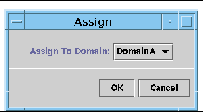
3. Right-click the Assign To Domain button to see a pull-down list of all domains.
4. Choose a domain from the domain list, then click the OK button to assign the selected board to that domain.
5. Complete this procedure with one of the following actions:
- Click OK to assign the selected board to the domain and close this window.
- Click Cancel to cancel your request.
If this action fails, an error message is displayed in the status message field of the Assign panel.
 To Unassign Boards To Unassign Boards
|
1. Right-click a board entry in the data table to display a pop-up menu.
2. Choose Unassign.
The Unassign panel (FIGURE 3-6) is displayed.
FIGURE 3-6 Unassign Panel
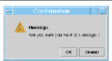
3. Complete this procedure with one of the following actions:
- Click OK to unassign the selected board from the domain and close this window.
- Click Cancel to cancel your request.
If this action fails, an error message is displayed in the status message field of the Unassign panel.
 To Power On or Off Boards To Power On or Off Boards
|
1. Right-click a board entry in the data table to display a pop-up menu.
The board power status is either Powered On or Powered Off, and can be toggled from one state to the other.
2. Select Power Off (or Power On).
The appropriate panel is displayed. FIGURE 3-7 shows the Power Off panel.
FIGURE 3-7 Power Off Panel
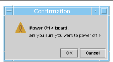
3. Complete this procedure with one of the following actions:
- Click OK to power off (or power on) the selected board for the domain and close this window.
- Click Cancel to cancel your request.
If this action fails, an error message is displayed in the status message field of the Power Off (or Power On) panel.
 To Test a Board To Test a Board
|
|
Note - You can test only CPU boards.
|
1. Right-click in the data table to display a pop-up menu.
2. Choose Test.
The Test panel is displayed. FIGURE 3-8 shows the Test Board panel for a selected board and a message about the test time.
FIGURE 3-8 Test Board Panel
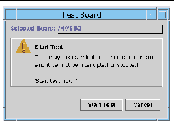
|
Note - This panel is displayed only for boards that are assigned but disconnected or for boards that are available.
|
3. Click the Start Test button to start a test, or click the Cancel button to close the panel without taking any action.
The test status is displayed in the status message field at the bottom of the panel. The test may take a long time. While the test is in progress, the panel shows a busy cursor.
If the test action fails, an error message is displayed in the status message field.
 To Set Up the System Controller To Set Up the System Controller
|
1. Right-click in the data table to display a pop-up menu.
2. Choose System Controller Setup.
The System Controller Network Setup panel (FIGURE 3-9) is displayed.
FIGURE 3-9 System Controller Network Setup Panel
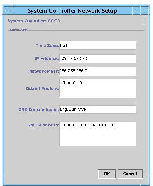
3. Modify the information as needed by editing the individual fields.
|
Note - There is no validation of the changes that you make.
|
4. Choose one of the following actions:
- Click OK to accept the changes you made and close this window.
- Click Cancel to cancel your request.
If any error is encountered while retrieving any information, an error message is displayed in the status message field.
5. If you have changed an IP address:
a. Reboot the system controller.
The IP address change does not take effect until the system controller is rebooted.
b. Rerun the setup procedure for the Sun Fire Midrange Systems Platform Administration Module on the agent machine.
See To Set Up the Platform Agent Using the Setup Wizard.
 To Set Up Loghosts and SNMP Trap Hosts To Set Up Loghosts and SNMP Trap Hosts
|
You can use the Setup Loghosts panel to set up SNMP trap and Syslog hosts for a system.
1. Right-click in the data table to display a pop-up menu.
2. Choose Setup Loghosts.
The Setup Loghosts panel (FIGURE 3-10) is displayed.
FIGURE 3-10 Setup Loghosts Panel
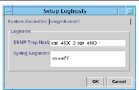
3. Right-click the System Controller list box to display a list of system controllers.
4. Choose a system controller.
Information about the SNMP trap host and Syslog hosts for the selected system controller is displayed.

|
Caution - Sun Management Center software for Sun Fire midrange systems does not function without an SNMP trap host.
|
5. You can add or change the entry for Syslog Loghost.
You can enter multiple Syslog hosts, one per line.
6. You can add or change the entry for SNMP Trap Host.
The SNMP trap host must be the Sun Management Center server.
7. Complete this procedure with one of the following actions:
- Click OK to accept the changes you made and close this window.
- Click Cancel to cancel your request.
If an action fails, an error message is shown in the status message field at the bottom of the panel.
 To Display FRU Information To Display FRU Information
|
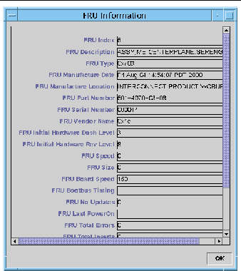
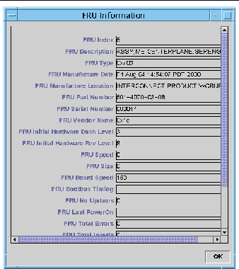
This panel displays the FRU information of a specific component. This panel is read only, and no information can be changed.
1. Choose FRU Information...
The FRU Information panel (FIGURE 3-11) is displayed.
FIGURE 3-11 FRU Information Panel
2. Click OK to close this window.
 To Display Host Details To Display Host Details
|
1. Right-click in the data table to display a pop-up menu.
2. Choose Host Details.
The Host Details window of the corresponding hardware domain is displayed.
3. Click OK to close this window.
 To Change a Domain Access Control List To Change a Domain Access Control List
|
1. Choose ACL...
The Access Control List (FIGURE 3-12) panel is displayed.
FIGURE 3-12 Access Control List Panel
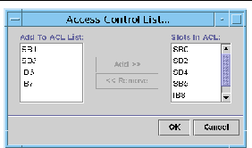
A list of slots that are not present in the ACL of a selected domain is displayed in the Add to ACL List pane. A list of slots that are present in the ACL of a selected domain is displayed in the Slots in ACL pane.
2. Choose one or more entries in the Add to ACL List pane and click the Add >> button.
The selected boards are added to the Slot in ACL list.
3. Choose one or more entries in the Slots ACL List pane, and click the << Remove button.
The selected boards are removed from the Slot in ACL list.
4. Complete this procedure with one of the following actions:
 Click OK to accept the changes you made and close this window.
 Click Cancel to cancel your request.
If an operation fails, an error message is displayed in the status message field.
Accessing the Domain Tables in the Platform Administration Module
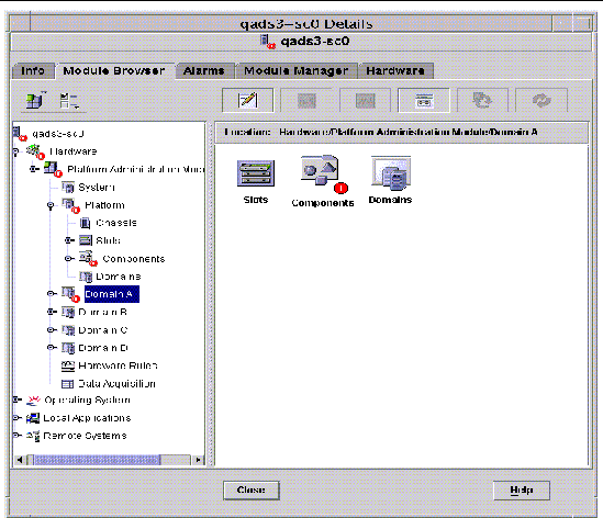
A domain administrator can view all the tables for the corresponding domain node that the administrator administers. For example, the domain administrator for Domain A can view all tables under Domain A (FIGURE 3-13). The domain tables and their properties are summarized in this section.
FIGURE 3-13 Domain X Tables
Domain X Slot Tables
This section contains the slot tables for a specific domain, where X is the letter of the domain (A-D):
- Empty Slots
- CPU Boards
- I/O Boards
- Unknown Boards
Domain X Empty Slots
TABLE 3-19 provides a brief description of the properties for empty slots on a specific domain for Sun Fire midrange systems.
TABLE 3-19 Domain X Empty Slots
|
Property
|
Rule (if any)
|
Description
|
|
Slot Name
|
|
Displays the names of empty slots, such as SBx, where x is the slot number.
|
|
Slot Power Status
|
rspa1011
|
Displays the power status: PoweredOff or PoweredOn
|
|
Slot Board Type
|
|
Displays the board type: Empty
|
|
Slot State
|
|
Displays the slot state: Active, Assigned, Available, or --, which means the board state does not apply to this slot
|
|
Slot Test Status
|
rspa1010
|
Displays the slot test status: Passed, NotTested, Unknown, Under Test, Start Test, Degraded, Failed, or Unusable
|
|
Slot Domain
|
|
Displays the domain to which the slot is assigned, such as Isolated or DomainA
|
|
Slot Status
|
rspa1000
|
Displays the slot status: OK, Failed, OverTemp, UnderTemp, or Unknown
|
Domain X CPU Boards
TABLE 3-20 provides a brief description of the properties for CPU boards on a specific domain for Sun Fire midrange systems.
TABLE 3-20 Domain X CPU Boards
|
Property
|
Rule (if any)
|
Description
|
|
CPU Board Name
|
|
Displays the identifier of the CPU board: SBx, where x is the slot number containing the CPU board
|
|
CPU Board Power Status
|
rspa1011
|
Displays the power status: PoweredOff or PoweredOn
|
|
CPU Board Type
|
|
Displays the CPU board revision number : CPU (default), CPU_V2, CPU_V3, or Unknown.
|
|
CPU Board Slot State
|
|
Displays the slot state: Active, Assigned, Available, or --, which means the board state does not apply to this slot
|
|
CPU Board Test Status
|
rspa1010
|
Displays the board test status: Passed, NotTested, Unknown, Under Test, Start Test, Degraded, Failed, or Unusable
|
|
CPU Board Domain
|
|
Displays the domain to which the board is assigned
|
|
Slot Status
|
rspa1000
|
Displays the slot status: OK, Failed, OverTemp, UnderTemp, or Unknown
|
|
CPU Board Fru Index
|
|
Displays the field-replaceable unit (FRU) index for the CPU board
|
|
CPU Board Total CPU
|
|
Displays the total number of CPUs on this board, such as 4
|
|
CPU Board Total Dram Memory (MB)
|
|
Displays the total amount of dynamic random access memory (DRAM) in megabytes (MB) on this board, such as 4096
|
|
CPU Board Total Ecache Memory (MB)
|
|
Displays the total amount of external cache (Ecache) in megabytes (MB) on this board, such as 32
|
|
CPU Board Total WCI
|
|
Displays the total number of Sun Fire Link interfaces (WCIs) on the CPU board
|
|
CPU Board Temperature
|
|
Displays the CPU board temperature and range in the format: #ofTemp-Values|lower-limit:actual-temp-value:upper-limit:token|..|), where token is one of the following: normal, over-heat, under-heat, unknown. An example is 4|0:32:90:normal|0:33:9...
|
|
Is Cod Board?
|
|
States whether the CPU board is also a COD board (CodBoard or NonCodBoard)
|
Domain X I/O Boards
TABLE 3-21 provides a brief description of the properties for I/O boards on a specific domain for Sun Fire midrange systems.
TABLE 3-21 Domain X I/O Boards
|
Property
|
Rule (if any)
|
Description
|
|
IO Board Name
|
|
Displays the board identifier: /Nn/IBx, where n is the node number and x is the slot number containing the I/O board
|
|
IO Board Power Status
|
rspa1011
|
Displays the power status: PoweredOff or PoweredOn
|
|
IO Board Type
|
|
Displays the board type, such as PCI, PCI+, or CPCI
|
|
IO Board Slot State
|
|
Displays the slot state: Active, Assigned, Available, or --, which means the board state does not apply to this slot
|
|
IO Board Test Status
|
rspa1010
|
Displays the board test status: Passed, NotTested, Unknown, Under Test, Start Test, Degraded, Failed, or Unusable
|
|
IO Board Domain
|
|
Displays the domain to which the board is assigned
|
|
Slot Status
|
rspa1000
|
Displays the slot status: OK, Failed, OverTemp, UnderTemp, or Unknown
|
|
IO Board Fru Index
|
|
Displays the field-replaceable unit (FRU) index for the I/O board
|
|
IO Board Total WCI
|
|
Displays the total number of Sun Fire Link interfaces (WCIs) on this IO board
|
|
IO Board Total ParoliCpciDca
|
|
Displays the total number of parallel optical link (Paroli) cards, compact PCI (cPCI) cards, and daughter-card assemblies (DCAs) on this IO board
|
|
IO Board Temperature
|
|
Displays the temperature and range of the I/O board in the format: #ofTemp-Values|lower-limit:actual-temp-value:upper-limit:token|..|), where token is one of the following: normal, over-heat, under-heat, unknown. An example is 2|0:46:90:normal|0:35...
|
Domain X Unknown Boards
TABLE 3-22 provides a brief description of the properties for unknown boards on a specific domain for Sun Fire midrange systems.
TABLE 3-22 Domain X Unknown Boards
|
Property
|
Rule (if any)
|
Description
|
|
Unknown Board Name
|
|
Displays the unknown board name, such as SBx or IBx, where x is the slot number containing the board
|
|
Unknown Board Power Status
|
rspa1011
|
Displays the power status: PoweredOff or PoweredOn
|
|
Unknown Board Type
|
|
Displays the board type: Unknown
|
|
Unknown Board Slot State
|
|
Displays the slot state: Active, Assigned, Available, or --, which means the board state does not apply to this slot
|
|
Unknown Board Test Status
|
rspa1010
|
Displays the board test status: Passed, NotTested, Unknown, Under Test, Start Test, Degraded, Failed, or Unusable
|
|
Unknown Board Domain
|
|
Displays the domain to which the board is assigned
|
|
Slot Status
|
rspa1000
|
Displays the slot status: OK, Failed, OverTemp, UnderTemp, or Unknown
|
Domain X Component Tables
This section contains the component tables for a specific domain, where X is the letter of the domain (A-D):
- CPU Module
- DIMM
- Ecache
- WCI
- WCI Port
Domain X CPU Module
TABLE 3-23 provides a brief description of the properties for CPU modules on a specific domain for Sun Fire midrange systems.
TABLE 3-23 Domain X CPU Module
|
Property
|
Rule (if any)
|
Description
|
|
CPU Module Board Index
|
|
Displays the board index for the CPU module
|
|
CPU Module Index
|
|
Displays the index for the CPU module
|
|
CPU Module Description
|
|
Displays the description of the CPU module, such as UltraSPARC-III, UltraSPARC-III+, UltraSPARC-IV, or UltraSPARC-IV+
|
|
CPU Module Temperature
|
|
Displays the temperature and range of the CPU module in the format: #ofTemp-Values|lower-limit:actual-temp-value:upper-limit:token|..|), where token is one of the following: normal, over-heat, under-heat, unknown. An example is 1|0:62:93:normal
|
|
CPU Module Status
|
rspa1008
|
Displays the status of the CPU module: Online or Idle. Displays CodDisabled if the CPU is disabled by COD.
|
|
CPU Module Model
|
|
Displays the model of the CPU module, such as sparcv9
|
|
CPU Module Speed (MHz)
|
|
Displays the speed of the CPU module in megahertz (MHz)
|
|
CPU Module Icache Size (KB)
|
|
Displays the size of the CPU module instruction cache (Icache) in kilobytes (KB)
|
|
CPU Module Dcache Size (KB)
|
|
Displays the size of the CPU module data cache (Dcache) in kilobytes (KB)
|
|
CPU Module Ecache Size (KB)
|
|
Displays the size of the CPU module external cache (Ecache) in kilobytes (KB)
|
|
CPU Module Wcache Size (KB)
|
|
Displays the size of the CPU module write cache (Wcache) in kilobytes (KB)
|
|
CPU Module Last Change
|
|
Displays the date and time of the last change
|
|
CPU Module Errors
|
|
Displays the number of error-correcting code (ECC) errors for the CPU module
|
Domain X Components - DIMM
TABLE 3-24 provides a brief description of the properties for a dual inline memory module (DIMM) on a specific domain for Sun Fire midrange systems.
TABLE 3-24 Domain X Components - DIMM
|
Property
|
Rule (if any)
|
Description
|
|
DIMM CPU Board Index
|
|
Displays the CPU board index for the DIMM
|
|
DIMM CPU Module Index
|
|
Displays the CPU module index for the DIMM
|
|
DIMM Index
|
|
Displays the DIMM index
|
|
DIMM Fru Index
|
|
Displays the field-replaceable unit (FRU) index for the DIMM
|
Domain X Components - Ecache
TABLE 3-25 provides a brief description of the properties for external cache (Ecache) on a specific domain for Sun Fire midrange systems.
TABLE 3-25 Domain X Components - Ecache
|
Property
|
Rule (if any)
|
Description
|
|
Ecache CPU Board Index
|
|
Displays the CPU board index for the Ecache
|
|
Ecache CPU Module Index
|
|
Displays the CPU module index for the Ecache
|
|
Ecache Index
|
|
Displays the Ecache index
|
|
Ecache Fru Index
|
|
Displays the field-replaceable unit (FRU) index for the Ecache
|
Domain X Components - WCI
TABLE 3-26 provides a brief description of the properties for the Sun Fire Link Interface (WCI) module for a specific domain on Sun Fire midrange systems.
TABLE 3-26 Domain X Components - WCI
|
Property
|
Rule (if any)
|
Description
|
|
WCI Module Board Index
|
|
Displays the board index for the WCI module
|
|
WCI Module Index
|
|
Displays the index for the WCI module
|
|
WCI Module Description
|
|
Displays the description of the WCI module
|
|
WCI Module Status
|
rspa1008
|
Displays the status of the WCI module: Online or Idle
|
|
WCI Module Mode
|
|
Displays the mode of the WCI module: SSM (scalable shared memory), RSM (remote shared memory), and Unknown
|
|
WCI Module Temperature
|
|
Displays the temperature and range of the WCI module in the format: #ofTemp-Values|lower-limit:actual-temp-value:upper-limit:token|..|), where token is one of the following: normal, over-heat, under-heat, unknown.
|
|
WCI Module Total DIMM
|
|
Displays the total size of the DIMM on the WCI module
|
|
WCI Module Total MEM
|
|
Displays the size of total memory on the WCI module
|
|
WCI Module Total ParoliDCA
|
|
Displays the total number of parallel optical link (Paroli) cards and daughter-card assemblies (DCAs) on this module.
|
|
WCI Module Total Port
|
|
Displays the total number of ports for the WCI module
|
|
WCI Module Last Change
|
|
Displays the date and time of the last change
|
|
WCI Module Errors
|
|
Displays the number of error-correcting code (ECC) errors for the WCI module
|
Domain X Components - WCI Port
TABLE 3-27 provides a brief description of the properties for the Sun Fire Link Interface (WCI) port on a specific domain for Sun Fire midrange systems.
TABLE 3-27 Domain X Components - WCI Port
|
Property
|
Rule (if any)
|
Description
|
|
WCI Port Board Index
|
|
Displays the board index for the WCI port
|
|
WCI Port Module Index
|
|
Displays the module index for the WCI port
|
|
WCI Port Index
|
|
Displays the index for the WCI port
|
|
WCI Port Fru Index
|
|
Displays the field-replaceable unit (FRU) index for the WCI port
|
|
WCI Port Status
|
|
Displays the status for the WCI port: Unknown, Installed, Connected, Unconfigured, and Error
|
|
WCI Port ParoliDCA
|
|
Displays the number of parallel optical link (Paroli) cards and daughter-card assemblies using this WCI port (1 or 2)
|
|
WCI Port Remote Location
|
|
Displays the remote location for the WCI port
|
Domains
See Platform Domains for information about properties for a specific domain.
Table listing properties for specific domains, their descriptions, and any related rules.
Taking Action on a Domain Table
When you right-click an entry in a data table, a set of actions is displayed in a pop-up menu (FIGURE 3-14). In the menu, the list of actions varies, depending on the column values in the row that you choose and on the type of entry.
FIGURE 3-14 Module Browser Window Domains Table
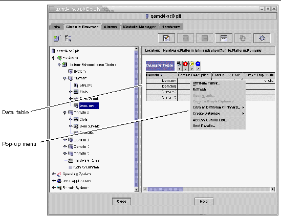
TABLE 3-28 lists the types of entries that can appear in the menus, and the type of actions that can be taken.
TABLE 3-28 Table Action Menu Items for the Domain View
|
Table
|
Action
|
|
Slots and Components tables that have FRU Index entries
|
View FRU information
|
|
Domains
|
View and manage Keyswitch, Setup Loghost, and Host details
|
TABLE 3-29 lists some common actions and their corresponding functions.
TABLE 3-29 Domain Table Actions
|
Action
|
Function
|
|
Keyswitch...
|
Enables you to change the virtual keyswitch position of a domain. FIGURE 3-15 shows the panel that is displayed when you choose Keyswitch...
|
|
Setup Loghosts...
|
Enables you to set up the SNMP Trap and Syslog hosts for a domain. FIGURE 3-16 shows the panel that is displayed when you choose Setup Loghosts...
|
|
FRU Information
|
Enables you to see the FRU information for the selected component. FIGURE 3-17 shows the panel that is displayed.
|
|
Table sorting
|
Enables you to sort the domain table according to different criteria. When you click on the domain table column headers, the table is sorted according to that criteria. For example, clicking the Status column, sorts the table Status. You can toggle the sort order, ascending and descending, by clicking on the same column header again. The current sorted column header is displayed in bold face and the current sort order is displayed as a down or up arrow. By default the domain table is in ascending order by domain IDs.
|
|
Host Details
|
Displays the host Details window of the corresponding domain.
|
The following sections explain how to implement these actions.
 To Change a Domain Keyswitch Setting To Change a Domain Keyswitch Setting
|
The Keyswitch menu item is available for the individual domains (Domain A, B, C, or D).
1. Right-click in the data table to display a pop-up menu.
2. Choose Keyswitch...
In the Hierarchy view, the path to this command is Hardware > Platform Administration Module > Domain X > Domains > data table menu > Keyswitch....
The Keyswitch panel (FIGURE 3-15) is displayed. This panel shows the current position of the virtual keyswitch.
FIGURE 3-15 Keyswitch Panel
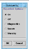
If the system controller is networked, you can change the keyswitch position to one of five modes. If the system controller is not networked, you cannot choose an option.
The five modes are:
If the domain is already powered on, selecting On changes only the position on the virtual keyswitch.
If the domain is running the Solaris Operating System, a confirmation panel is displayed when you choose Off. Choosing this mode changes the board state of all the boards in the selected domain to Off and places the boards in low-power mode, allowing them to be physically removed from the chassis.
If the domain is already powered on, selecting Diagnostic changes only the position on the virtual keyswitch.
If the domain is already powered on, selecting Secure changes only the position on the virtual keyswitch.
If the domain is running the Solaris Operating System, a confirmation panel is displayed when you choose Standby. Choosing this mode changes the state of all boards in the selected domain to Standby, but does not put the boards in the low- power mode.
3. Complete this procedure with one of the following actions:
- Click OK to accept the changes you made and close this window.
- Click Cancel to cancel your request.
If an error occurs, it is displayed in the status message field of the panel.
 To Set Domain Loghosts To Set Domain Loghosts
|
1. Right-click in the data table to display a pop-up menu.
2. Choose Setup Loghosts...
In the Hierarchy view:
- Choose Hardware > Platform Administration Module > Domain X > Domains > data table menu > Setup Loghosts....
- Choose Hardware > Platform Administration Module > Platform > Chassis > data table menu > Setup Loghosts....
The Setup Loghosts panel (FIGURE 3-16) is displayed.
FIGURE 3-16 Setup Loghosts Panel
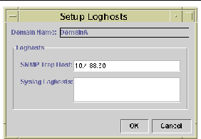
3. You can change the values for SNMP Trap Host and Syslog Loghosts.
You can specify multiple loghosts by entering one IP address or node name per line.
4. Complete this procedure with one of the following actions:
 Click OK to accept the changes you made and close this window.
 Click Cancel to cancel your request.
If an error occurs, an error message is displayed in the status message field.
 To Display FRU Information To Display FRU Information
|
This panel displays FRU information for a specific component.
No information can be changed. The panel is read only.
1. Right-click in the data table to display a pop-up menu.
2. Choose FRU Information...
In the Hierarchy view, choose Hardware > Platform Administration Module > Platform (or Domain X) > Slots (or Components) > category, data table menu > FRU Information....
The FRU Information panel (FIGURE 3-17) is displayed.
3. Click OK to close this window.
FIGURE 3-17 FRU Information Panel
 To Display Host Details To Display Host Details
|
1. Right-click in the data table to display a pop-up menu.
2. Choose Host Details...
In the Hierarchy view, choose Hardware > Platform Administration Module > Platform (or Domain X) > Domains > data table menu > Host Details....
The Host Details window of the corresponding hardware domain is displayed.
3. Click OK to close this window.
Physical View and Logical View of Sun Fire Midrange Systems
These views can be seen by both the platform administrator and the domain administrator. The properties and values shown in the Physical View and the Logical View are produced by the Config-Reader. To view tables of available properties and values, see Accessing Tables in the Domain Config-Reader Module. For a description of platform administration alarm rules, see Platform Administration Hardware Rules.
|
Note - Not all alarms are displayed in the Physical View and Logical View.
|
For general information on the physical and logical views, refer to the Sun Management Center User's Guide.
 To See Physical and Logical Views To See Physical and Logical Views
|
1. In the Sun Management Center console, double-click a Sun Fire midrange systems icon.
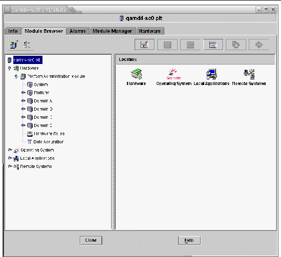
The Details window is displayed (FIGURE 3-18).
FIGURE 3-18 Platform Details Window
2. Choose the Hardware tab in the Details window.
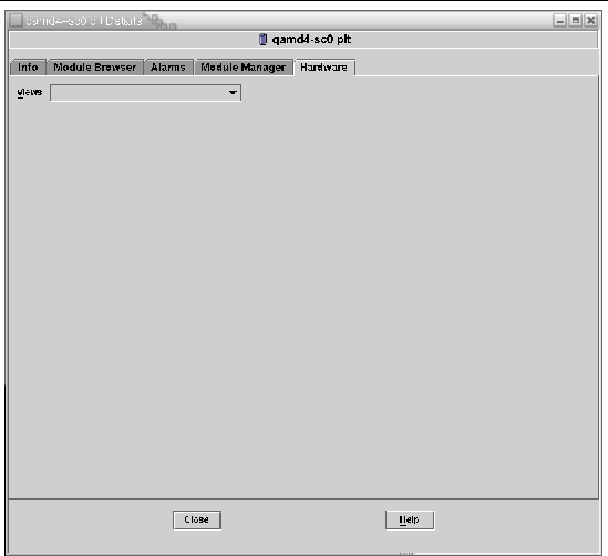
The following is displayed (FIGURE 3-19).
FIGURE 3-19 Hardware Tab
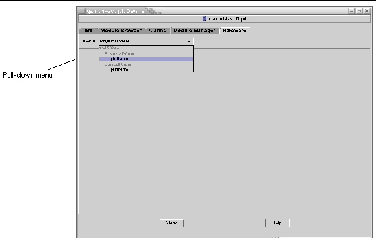
3. In the Views pull-down menu (FIGURE 3-20), choose "platform" under either "Physical View" or "Logical View."
FIGURE 3-20 Views Pull-Down Menu
The chosen view is displayed.
- If you chose the Physical View (FIGURE 3-21), slowly move the cursor over the image of the system. Field-replaceable units (FRUs) are highlighted as the cursor passes over them. If you hold the cursor still for several seconds, the corresponding properties and values are displayed in the Properties window.
FIGURE 3-21 Physical View (Rear View of Sun Fire E4900 System)
- If you chose the Logical View (FIGURE 3-22), click an icon to display its properties in the Properties window. You can double-click some icons to see various component parts, or click the Expand All button to see all the component parts in the system. Various properties and values are displayed in the Properties window.
FIGURE 3-22 Logical View
The Logical View has three additional buttons, marked Search, Expand All, and Refresh Details.
- The Search button launches a pop-up Search window (FIGURE 3-23). To use the Search window, enter a component name or path, then click the Find button to find the first instance of the term. The Search feature expands the Logical View if necessary, and highlights the term it has located. To find additional instances of the same term, click the Next button. To close the Search window, click the Cancel button.
FIGURE 3-23 Search Button in the Details Window Logical View
|
Tip - The Search function is case sensitive. The error message "Node not found" is displayed at the bottom of the Details window if the search does not locate the component in your system.
The Search function stops searching when it reaches the bottom of the Logical View window, and the error message "Node not found" is displayed at the bottom of the Details window.
|
|
Tip - You can use the Module Browser tab displays to compare data for all similar components. You can use the Hardware tab Physical and Logical views to see data for an individual component in the system. For example, double-click the DIMM table icon in the Module Browser tab to see a table that lists properties for all DIMMs in the system. To see properties for dimm(0), use the Search Button in the Logical view.
|
- The Expand All button expands all icons displayed the Logical View, allowing you to see all components and subassemblies, and so forth. The button name toggles to "Recover Default," and you can click the button to recompress the icon display.
- The Refresh Details button updates the Property/Value table (in the right side of the viewing window).
Platform Administration Hardware Rules
This section describes the alarm rules for the Platform Administration Module. The system provides a message with the alarms telling what the current property is and what the limit is.
Slot Status Rule (rspa1000)
The slot status rule generates an alarm when the slot status of a board is not OK, Unknown, or null. If field-replaceable unit (FRU) information is available, the alarm message includes the FRU information.
TABLE 3-30 Platform Administration Slot Status Rule
|
Slot Status
|
Alarm Level
|
Meaning
|
|
OverTemp
|
Info
|
Temperature is over the upper limit.
|
|
UnderTemp
|
Info
|
Temperature is under the lower limit.
|
|
Failed
|
Critical/Error
|
Board failed.
|
Action:
Check to see whether the hardware needs replacing. In case of an OverTemp status, ensure that the fans are on.
System Frequency Clock Rule (rspa1001)
The system frequency clock rule generates an alarm if the clock fails over to the spare system controller.
TABLE 3-31 Platform Administration System Frequency Clock Rule
|
Alarm Level
|
Meaning
|
|
Info
|
System frequency clock failed over to the spare system controller.
|
Action:
This alarm is for your information; you may need to check the original clock status.
Domain Status Rule (rspa1002)
The domain status rule generates a critical alarm if the domain status is not either Active or RunningSolaris.
TABLE 3-32 Platform Administration System Domain Status Rule
|
Alarm Level
|
Meaning
|
|
Critical/Error
|
Domain is in a critical status.
|
Action:
When a domain is running the power-on self-test (POST) and is coming up, the alarm is generated. If the alarm does not disappear for a long time, the domain may be hung. In this case, check the domain status and the booting slice.
Domain Keyswitch Rule (rspa1003)
The domain keyswitch rule generates an information alarm when the domain keyswitch changes from one state to another.
TABLE 3-33 Platform Administration System Domain Keyswitch Rule
|
Alarm Level
|
Meaning
|
|
Info
|
Domain keyswitch changed to a new state.
|
Action:
This alarm is for your information; no action is necessary.
System Controller Failover Rule (rspa1004)
The system controller failover rule generates an information alarm when the SC fails over from the main SC to the spare SC.
TABLE 3-34 Platform Administration System Controller Failover Rule
|
Alarm Level
|
Meaning
|
|
Info
|
System controller failed over from the main SC to the spare SC.
|
Action:
This alarm is for your information only; no action is needed.
System Controller Change Rule (rspa1005)
The system controller change rule generates information alarms for certain changes in the SC.
TABLE 3-35 Platform Administration System Controller Change Rule
|
Value
|
Alarm Level
|
Meaning
|
|
1
|
Info
|
System controller has come up.
|
|
2
|
Info
|
System controller's IP address has changed.
|
Action:
This alarm is for your information only; no action is needed.
Log or Trap Host Change Rule (rspa1006)
The log or trap host change rule generates an information alarm if platform or domain log or trap hosts change.
TABLE 3-36 Platform Administration Log or Trap Host Change Rule
|
Alarm Level
|
Meaning
|
|
Info
|
Change has been made to the domain log host (domainloghost), the domain trap host (domaintraphost), the platform log host (chassisloghost), or the platform trap host (chassistraphost).
|
Action:
This alarm is for your information only; no action is needed.
System Controller Not Responding Rule (rspa1007)
The system controller not responding rule generates a critical alarm if the SC is not responding or if the SNMP agent on the main SC is not responding.
TABLE 3-37 Platform Administration System Controller Not Responding Rule
|
Value
|
Alarm Level
|
Meaning
|
|
0
|
Critical
|
System controller is not responding.
|
|
1
|
Critical
|
Main SC's SNMP agent is not responding.
|
Action:
Contact your Sun service personnel.
CPU Module Status Rule (rspa1008)
The CPU module status rule generates a critical alarm when any CPU module is in a state other than Idle or Online.
TABLE 3-38 Platform Administration Log or Trap Host Change Rule
|
Alarm Level
|
Meaning
|
|
Critical
|
Status of the CPU module is critical.
|
Action:
Contact your Sun service personnel.
System Controller Firmware Version Rule
The system controller firmware (SCApp) version rule generates a critical alarm if the SC firmware is before version 5.12.5.
TABLE 3-39 Platform Administration SC Firmware Version Rule
|
Alarm Level
|
Meaning
|
|
Critical
|
Version of SCApp firmware is older than 5.12.5.
|
Action:
Update the system controller firmware (SCApp).
System Board Test Status Rule (rspa1010)
The system board test status rule generates alarms if the test status is not Unknown, NoTested, or Passed (TABLE 3-40).
TABLE 3-40 Platform Administration System Board Test Status Rule
|
Test Status
|
Alarm Level
|
Meaning
|
|
UnderTest
|
Info
|
POST is testing the board.
|
|
StartTest
|
Info
|
POST is starting to test the board.
|
|
Degraded
|
Warning
|
Board is running in a degraded mode.
|
|
Failed
|
Critical
|
Board failed in POST testing.
|
|
Unusable
|
Critical
|
Board is not usable in this system.
|
|
--
|
Critical
|
Test Status is indeterminate.
|
Action:
- If the board test status is UnderTest or StartTest, the alarm is for your information only; no action is needed.
- If the board test status is Degraded, check the root cause of the degrade. For example, it could be caused by an insufficient COD license.
- If the board test status is Failed or Unusable, the board needs to be replaced.
Domain or Board Power State Rule (rspa1011)
The domain or board power state rule generates an information alarm when any component is powered off (PoweredOff) or a caution alarm when the power state of a component is unknown.
TABLE 3-41 Platform Administration Domain or Board Power State Rule
|
Alarm Level
|
Meaning
|
|
Info
|
Component is powered off.
|
|
Caution
|
Power state of a component is unknown.
|
Action:
These alarms are for your information only; no action is needed.
Data Acquisition Table
The Data Acquisition Table allows you to refresh the table for each property to keep your data current. The Data Acquisition Table has 15 properties, each of which represents one table of data in the SC database:
- Chassis
- Slots
- CPU Board
- I/O Board
- Address Repeater Board
- CPU Module
- DIMM
- Ecache
- WCI
- WCI Port
- Domains
- Fan
- Power Supply
- System Controller
- FRU
You can right-click on a property, and left-click Refresh in the pop-up menu. The values in the table for that property are refreshed. The value for each property in this table is a localized timestamp indicating when the data in the table for that property was last acquired successfully from the SC database (FIGURE 3-24). This allows you to ensure that your data is current.
FIGURE 3-24 Data Acquisition Table
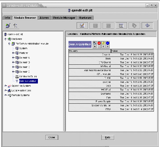
The members of the following security access groups may view the contents of the Data Acquisition table:
- spltop
- spltadm
- sdaop
- sdaadm
- sdbop
- sdbadm
- sdcop
- sdcadm
- sddop
- sddadm
See TABLE 2-3 for definitions of the User Groups.
| Sun Management Center 3.5 Version 6 Supplement for Sun Fire Midrange Systems
|
819-0418-10
|
   
|
Copyright © 2005, Sun Microsystems, Inc. All Rights Reserved.


 Click OK to accept the changes you made and close this window.
 Click Cancel to cancel your request.


 Click OK to accept the changes you made and close this window.
 Click Cancel to cancel your request.


