| Sun Fire 6800/4810/4800/3800 Systems Site Planning Guide
|
    |
Environmental and Electrical Specifications
|
3.1 Environmental Requirements
The design of your environmental control system--such as computer room air-conditioning units--must ensure that intake air to the server system complies with the limits specified in this section.
To avoid overheating:
- Guard against directing any warmed air toward the bottom of the cabinet or standalone server.
- Guard against directing warmed air toward the server access panels.
The air intake screens act as electro-magnetic interference (EMI) and radio frequency interference (RFI) filters, stopping both EMI and RFI emissions from the system. These screens are a honeycomb type screen, which also collect and trap dust and debris particles.
The Sun Fire 6800/4810/4800 systems have been designed for maximum availability such that the air intake screens can be cleaned or changed without the need to power off the system.
The Sun Fire 6800/4810/4800 systems air intake screens require periodic inspection and cleaning. To prevent restricted airflow and possible equipment failure, the air intake screens should be inspected for debris and trapped particles every three months of operation. The level of debris found on the screens and surrounding area should be considered in the decision of when to remove and clean the air intake screen.
The environmental limits for Sun Fire 6800/4810/4800/3800 systems are listed in Environmental Limits for Sun Fire 6800/4810/4800/3800 Systems.
|
Note - When you receive your system, leave it in the shipping crate at its final destination for 24 hours in the environment in which you will install it. This is to prevent thermal shock and condensation.
|
TABLE 3-1 Environmental Limits for Sun Fire 6800/4810/4800/3800 Systems
|
Environmental
Factor
|
Temperature Range
|
Relative Humidity
|
Altitude
|
|
Operating
|
41°F to 95°F (5°C to 35°C)
derate 2°C for every 1 km up to 3 km
|
20% to 80%, 27°C max wet bulb (noncondensing)
|
sea level
to
9,843 ft
(3 km)
|
|
Nonoperating
|
-4°F to 140°F (-20°C to 60°C)
|
93%, 38°C max wet bulb (noncondensing)
|
39,370 ft
(12 km)
|
TABLE 3-2 Optimum Ambient Environmental Operating Conditions for Sun Fire 6800/4810/4800/3800 Systems
|
Environmental
Factor
|
Ambient Temperature Range
|
Ambient Relative Humidity
|
|
Operating
|
70°F to 73.5°F (21°C to 23°C)
|
45% to 50%,
|
The operating environmental limits in Table 3-1 reflect what the systems have been tested to, in order to meet all functional requirements. The optimum operating condition in Table 3-2 is the recommended operating environment. Operating computer equipment for extended periods of time at or near the temperature or humidity extremes is known to significantly increase the failure rate of hardware components.
|
Note - In order to minimize any chance of down-time due to component failure, it is strongly recommended that customers plan and use the optimal temperature and humidity ranges.
|
3.1.1 Ambient Temperature Recommendations
The ambient temperature range of 70°F to 74°F (21°C to 23°C) is optimal for system reliability and operator comfort levels. Most computer equipment can operate within a wide temperature range, but a level near 72°F (22°C) is desirable because it is easier to maintain safe associated relative humidity levels at this temperature. Operating in this temperature range provides a safety buffer just in case the environmental support systems go down for a period of time. Though individual standards vary slightly, 70°F to 74°F (21°C to 23°C) should be used as an optimal recommendation.
3.1.2 Ambient Relative Humidity Recommendations
The ambient relative humidity levels between 45% and 50% are the most suitable for safe data processing operations. Under certain circumstances, most data processing equipment can operate within a fairly wide environmental range (20% to 80%), but the optimal goal should be between 45% to 50% for several reasons:
- The optimal range helps protect computer systems from corrosivity problems associated with high humidity levels.
- It provides the greatest operating time buffer in the event of environmental control system failure.
- This range helps avoid failures or temporary malfunctions caused by intermittent interference from static discharges that occur when relative humidity is too low.
Electrostatic discharge (ESD) is easily generated and less easily dissipated in areas where the relative humidity is below 35%, and becomes critical when levels drop below 30%. The 5% relative humidity range may seem unreasonably tight when compared to the guidelines used in typical office environments or other loosely controlled areas, but it is not so difficult to maintain in a data center because of the high efficiency vapor barrier and low rate of air changes normally present.
3.2 Facility Power Requirements
To prevent catastrophic failures, the design of your power system must ensure that adequate power is provided to your Sun Fire system. Use dedicated AC breaker panels for all power circuits that supply power to your system. Electrical work and installations must comply with applicable local, state, or national electrical codes.
Provide a stable power source, such as an uninterruptible power system (UPS), to reduce the possibility of component failures. If the computer equipment is subjected to repeated power interruptions and fluctuations, it is susceptible to a higher component failure rate than it would be with a stable power source. Every Sun Fire system requires its own customer-supplied circuit breaker and AC receptacle for each power cord.
Each power cord will also supply your system with proper earth ground. Sun has tested both Sun Fire 6800 cabinets and Sun Fire cabinets for radiated and conducted emissions and have determined there is no difference in emissions with or without a ground strap grounding the cabinets. No additional earth grounding is necessary but, it may be added if desired.
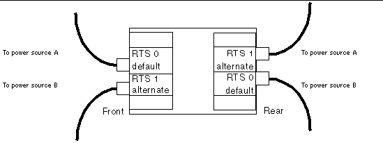
The Sun Fire 6800 system has dual Redundant Transfer Units (RTUs) with four Redundant Transfer Switches (RTSs). Two totally independent AC power sources are needed for input power redundancy. The AC power sources must be derived from independent power company utility feeds and Sun recommends that each be backed up with an on-line UPS. The power sources are not independent if they are only distinguished by having separate circuit breakers. One RTS hooked to an AC power source and the second RTS hooked to a UPS that is connected to the same AC power source is not supported because when the UPS is by-passed for maintenance both RTSs will be hooked up to the same source. If both RTSs are hooked to one utility feed then both lines must be backed up with on-line UPSs to ensure input power redundancy.
- In configurations with two RTU assemblies and two independent AC power sources there will be four cables to connect, two on the front, and two on the rear of the system (FIGURE 3-1).
FIGURE 3-1 Two RTU Assemblies and Two Independent AC Power Sources
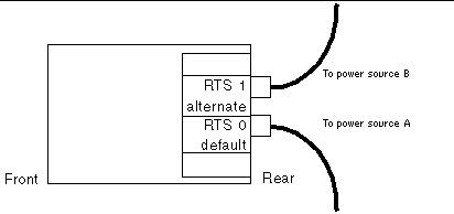
- In configurations with one RTU assembly and two independent AC power sources there will be two cables to connect, both in the rear of the system (FIGURE 3-2).
FIGURE 3-2 One RTU Assembly and Two Independent AC Power Sources
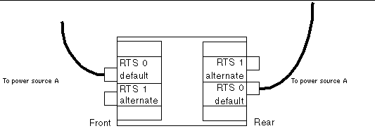
- In configurations with two RTU assemblies and one AC power sources there will be two cables to connect, one in the front (on the left), and one in the rear of the system (on the left) (FIGURE 3-3).

|
Caution - Connecting the alternate RTS units to outlets that use the same power source as the default RTS units is not supported and will adversely affect reliability.
|
FIGURE 3-3 Two RTU Assemblies and One AC Power Source
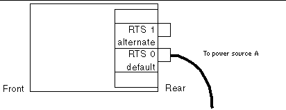
- In configurations with one RTU assembly and one AC power sources there will be only one cable to connect (in the rear of the system on the left) (FIGURE 3-4).

|
Caution - Connecting the alternate RTS unit to an outlet that uses the same power source as the default RTS unit is not supported and will adversely affect reliability.
|
FIGURE 3-4 One RTU Assembly and One AC Power Source
Every piece of support equipment requires its own customer-supplied circuit breaker and receptacle(s).
3.3 Electrical and Cooling Specifications
This section provides guidelines and requirements for cooling your Sun Fire systems. For electrical and cooling specifications, see the following tables:
Be aware of the following system cooling rules and guidelines:
- The room should have sufficient air-conditioning capacity to support the cooling needs of the entire system.
- The air-conditioning system should have controls that prevent excessive temperature changes.
TABLE 3-3 Electrical Specifications for Sun Fire 6800 Cabinet
|
Parameter
|
|
Value
|
|
Input current
|
Voltage range
Current, maximum
Current frequency range
|
200-240 VAC
34A at 208 VAC
47-63 Hz
|
|
Input power rating
Volt-ampere rating
BTU rating
Power factor
Connector type
|
Total continuous power
North American
International
|
6,460 W
6,800 VA
22,030BTU/hr
0.95 (with Sun Products)
4 - NEMA L6-30P for 200-240 VAC
4 - 32A, single-phase IEC 309, for 200-240 VAC1
|
|
Receptacle type
|
North American
|
4 - NEMA L6-30R for 200-240 VAC
|
TABLE 3-4 Electrical Specifications for Sun Fire Cabinet (Empty)
|
Parameter
|
|
Value
|
|
Input current
|
Voltage range
Current, maximum
Current frequency range
|
200-240 VAC
24A at 208 VAC for each RTU
47-63 Hz
|
|
Volt-Ampere rating
Connector type
|
North American
International
|
4,992 VA
NEMA L6-30P for 200-240 VAC
32A, single-phase IEC 309, for 200-240 VAC1
|
|
Receptacle type
|
North American
|
NEMA L6-30R for 200-240 VAC
|
TABLE 3-5 Electrical Specifications for Sun Fire 4810 System Not Mounted in the Sun Fire Cabinet
|
Parameter
|
|
Value
|
|
Input current
|
Voltage range
Current, maximum
Current frequency range
|
200-240 VAC
16.4A at 208 VAC for each power cord
(2+1 redundancy)
47-63 Hz
|
|
Input power rating
Volt-Ampere rating
BTU rating
Power factor
Connector type
|
Total continuous power
North American
International
|
3,120 W
3,280 VA
10,625 BTU/hr
0.95 (with Sun Products)
3 - NEMA 6-15P
3 - 10A, single-phase IEC 320, for 200-240 VAC1
|
|
Receptacle type
|
North American
|
3 - NEMA 6-15R for 200-240 VAC
|
TABLE 3-6 Electrical Specifications for Sun Fire 4800 System Not Mounted in the Sun Fire Cabinet
|
Parameter
|
|
Value
|
|
Input current
|
Voltage range
Current, maximum
Current frequency range
|
200-240 VAC
16A at 208 VAC for each power cord
(2+1 redundancy)
47-63 Hz
|
|
Input power rating
Volt-Ampere rating
BTU rating
Power factor
Connector type
|
Total continuous power
North American
International
|
3,040 W
3,200 VA
10,370 BTU/hr
0.95 (with Sun Products)
3 - NEMA 6-15P for 200-240 VAC
3 - 10A, single-phase IEC 320, for 200-240 VAC1
|
|
Receptacle type
|
North American
|
3 - NEMA 6-15R for 200-240 VAC
|
TABLE 3-7 Electrical Specifications for Sun Fire 3800 System Not Mounted in the Sun Fire Cabinet
|
Parameter
|
|
Value
|
|
Input current
Input power rating
Volt-ampere rating
BTU rating
|
Voltage range
Current, maximum
Voltage range
Current, maximum
Current frequency range
Total continuous power
|
100-120 VAC
24A at 100 VAC
19.7A at 120 VAC
(2+1 redundancy)
or
200-240 VAC
11.4A at 208 VAC
(2+1 redundancy)
47-63 Hz
2,280 W @ 100 VAC
2,240 W @ 120 VAC
2,170 W @200-240 VAC
2,400 VA @ 100 VAC
2,360 VA @ 120 VAC
2,280 VA @200-240 VAC
7,775 BTU/hr @ 100 VAC
7,645 BTU/hr @ 120 VAC
7,385 BTU/hr @ 200-240 VAC
|
|
Power factor
Connector type
|
North American
International
|
0.9 - 0.96 (with Sun Products)
3 - NEMA 5-15P for 100-120 VAC or
3 - NEMA 6-15P for 200-240 VAC
3 - 15A, single-phase IEC 320, for 200-240 VAC1
|
|
Receptacle type
|
North American
|
3 - NEMA 5-15R for 100-120 VAC or
3 - NEMA 6-15R for 200-240 VAC
|
3.4 Thermal Guidelines for Sun Fire 6800/4810/4800/3800 Systems
These guidelines are intended to assist those who would install the Sun Fire 6800/4810/4800/3800 systems at the end users' site. These guidelines address cooling issues only.
It is the ultimate responsibility of the end user to ensure that the environment in which these systems are mounted meet the following:
- All systems specifications
- Safety requirements specifications
3.4.1 Conditions
- Any systems mounted in a rack with Sun systems must have front to back cooling (no side to side).
- The front of the cabinet should not be facing, nor be in the path of the exhaust air from any other systems or cabinets.
- It is recommended that the cabinet allow 0.188 cubic meters per second (600 cubic feet per minute) of exhaust air out of the cabinet by way of the exhaust fans located at the top of the cabinet.
- The cabinet must allow for airflow to enter from the front and exhaust to the rear. Do not use a closed cabinet that prevents airflow into the front and out of the rear of the enclosure.
- A cabinet front filler panels must be attached so that no gaps appear between panels and between the panel and the system. If the panels cannot completely fill in the area above the system, make sure the gap appears at the top of the cabinet, away from the system. Cabinet front panels prevent hot air that is expelled from the rear of the cabinet from reentering the system from the front.
- Multiple systems in the same cabinet must be mounted as close together as possible without air gaps in between to avoid exhaust air recirculating back into the front air intake.
- All systems must be mounted in the lowest possible locations within the rack to prevent the cabinet from tipping over.
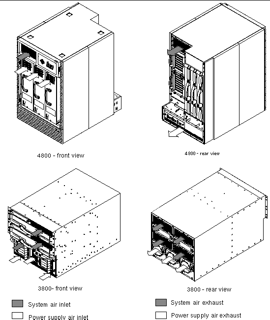
FIGURE 3-5 Sun Fire 6800 System Air Flow--Front and Rear
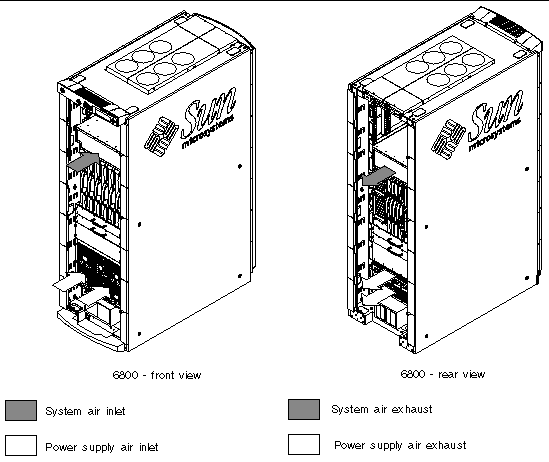
FIGURE 3-6 Sun Fire 4810 System Air Flow--Front and Rear
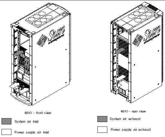
FIGURE 3-7 Sun Fire 4800 and 3800 Systems Air Flow--Front and Rear
