| Sun Fire Midrange Systems Platform Administration Manual
|
   
|
Mapping Device Path Names
|
This appendix describes how to map device path names to physical system devices. It describes the following topics:
Device Mapping
The physical address represents a physical characteristic that is unique to the device. Examples of physical addresses include the bus address and the slot number. The slot number indicates where the device is installed.
You reference a physical device by the node identifier--agent ID (AID). The AID ranges from 0 to 31 in decimal notation (0 to 1f in hexadecimal). In the device path beginning with ssm@0,0 the first number, 0, is the node ID.
CPU/Memory Mapping
CPU/Memory board and memory agent IDs (AIDs) range from 0 to 23 in decimal notation (0 to 17 in hexadecimal). Depending on the platform type, a system can have up to six CPU/Memory boards.
Each CPU/Memory board can have either two or four CPUs, depending on your configuration. Each CPU/Memory board has up to four banks of memory. Each bank of memory is controlled by one memory management unit (MMU), which is the CPU. The following code example shows a device tree entry for a CPU and its associated memory:
/ssm@0,0/SUNW/UltraSPARC-III@b,0 /ssm@0,0/SUNW/memory-controller@b,400000
|
where:
in b,0
- b is the CPU agent identifier (AID)
- 0 is the CPU register
in b,400000
- b is the memory agent identifier (AID)
- 400000 is the memory controller register
There are up to four CPUs on each CPU/Memory board (TABLE A-1):
- CPUs with AIDs 0-3 reside on board name SB0.
- CPUs with AIDs 4-7 on board name SB1.
- CPUs with AIDs 8-11 on board name SB2, and so on.
TABLE A-1 CPU and Memory Agent ID Assignment
|
CPU/Memory Board Name
|
Agent IDs on Each CPU/Memory Board
|
|
|
CPU 0
|
CPU 1
|
CPU 2
|
CPU 3
|
|
SB0
|
0 (0)
|
1 (1)
|
2 (2)
|
3 (3)
|
|
SB1
|
4 (4)
|
5 (5)
|
6 (6)
|
7 (7)
|
|
SB2
|
8 (8)
|
9 (9)
|
10 (a)
|
11 (b)
|
|
SB3
|
12 (c)
|
13 (d)
|
14 (e)
|
15 (f)
|
|
SB4
|
16 (10)
|
17 (11)
|
18 (12)
|
19 (13)
|
|
SB5
|
20 (14)
|
21 (15)
|
22 (16)
|
23 (17)
|
|
The first number in the columns of agent IDs is a decimal number. The number or letter in parentheses is in hexadecimal notation.
|
I/O Assembly Mapping
TABLE A-2 lists the types of I/O assemblies, the number of slots each I/O assembly has, and the systems the I/O assembly types are supported on.
TABLE A-2 I/O Assembly Type and Number of Slots per I/O Assembly by System Type
|
I/O Assembly Type
|
Number of Slots Per I/O Assembly
|
System Name(s)
|
|
PCI
|
8
|
Sun Fire E6900/E4900/6800/4810/4800 systems
|
|
CompactPCI
|
6
|
Sun Fire 3800 system
|
|
CompactPCI
|
4
|
Sun FireE6900/E4900/6800/4810/4800 systems
|
TABLE A-3 lists the number of I/O assemblies per system and the I/O assembly name.
TABLE A-3 Number and Name of I/O Assemblies per System
|
System Name(s)
|
Number of I/O Assemblies
|
I/O Assembly Name
|
|
Sun Fire E6900 and 6800 systems
|
4
|
IB6-IB9
|
|
Sun Fire 4810 system
|
2
|
IB6 and IB8
|
|
Sun Fire E4900 and 4800 systems
|
2
|
IB6 and IB8
|
|
Sun Fire 3800 system
|
2
|
IB6 and IB8
|
Each I/O assembly hosts two I/O controllers:
- I/O controller 0
- I/O controller 1
When mapping the I/O device tree entry to a physical component in the system, you must consider up to five nodes in the device tree:
- Node identifier (ID)
- ID controller agent ID (AID)
- Bus offset
- PCI or CompactPCI slot
- Device instance
TABLE A-4 lists the AIDs for the two I/O controllers in each I/O assembly.
TABLE A-4 I/O Controller Agent ID Assignments
|
Slot Number
|
I/O Assembly Name
|
Even I/O Controller AID
|
Odd I/O Controller AID
|
|
6
|
IB6
|
24 (18)
|
25 (19)
|
|
7
|
IB7
|
26 (1a)
|
27 (1b)
|
|
8
|
IB8
|
28 (1c)
|
29 (1d)
|
|
9
|
IB9
|
30 (1e)
|
31 (1f)
|
|
The first number in the column is a decimal number. The number (or a number and letter combination) in parentheses is in hexadecimal notation.
|
Each I/O controller has two bus sides: A and B.
- Bus A, which is 66 MHz, is referenced by offset 600000.
- Bus B, which is 33 MHz, is referenced by offset 700000.
The board slots located in the I/O assembly are referenced by the device number.
PCI I/O Assembly
This section describes the PCI I/O assembly slot assignments and provides an example of the device path.
The following code example gives a breakdown of a device tree entry for a SCSI disk:
/ssm@0,0/pci@19,700000/pci@3/SUNW,isptwo@4/sd@5,0
|
|
Note - The numbers in the device path are hexadecimal.
|
where:
in 19,700000
- 19 is the I/O controller agent identifier (AID).
- 700000 is the bus offset.
in pci@3
isptwo is the SCSI host adapter.
in sd@5,0
- 5 is the SCSI target number for the disk.
- 0 is the logical unit number (LUN) of the target disk.
This section describes the PCI I/O assembly slot assignments and provides an example of the device path.
TABLE A-5 lists, in hexadecimal notation, the slot number, I/O assembly name, device path of each I/O assembly, the I/O controller number, and the bus.
TABLE A-5 8-Slot PCI I/O Assembly Device Map for the Sun Fire Midrange Systems
|
I/O Assembly Name
|
Device Path
|
Physical Slot Number
|
I/O Controller Number
|
Bus
|
|
IB6
|
/ssm@0,0/pci@18,700000/pci@1
|
0
|
0
|
B
|
|
|
/ssm@0,0/pci@18,700000/pci@2
|
1
|
0
|
B
|
|
|
/ssm@0,0/pci@18,700000/pci@3
|
2
|
0
|
B
|
|
|
/ssm@0,0/pci@18,600000/pci@1
|
3
|
0
|
A
|
|
|
/ssm@0,0/pci@19,700000/pci@1
|
4
|
1
|
B
|
|
|
/ssm@0,0/pci@19,700000/pci@2
|
5
|
1
|
B
|
|
|
/ssm@0,0/pci@19,700000/pci@3
|
6
|
1
|
B
|
|
|
/ssm@0,0/pci@19,600000/pci@1
|
7
|
1
|
A
|
|
IB7
|
/ssm@0,0/pci@1a,700000/pci@1
|
0
|
0
|
B
|
|
|
/ssm@0,0/pci@1a,700000/pci@2
|
1
|
0
|
B
|
|
|
/ssm@0,0/pci@1a,700000/pci@3
|
2
|
0
|
B
|
|
|
/ssm@0,0/pci@1a,600000/pci@1
|
3
|
0
|
A
|
|
|
/ssm@0,0/pci@1b,700000/pci@1
|
4
|
1
|
B
|
|
|
/ssm@0,0/pci@1b,700000/pci@2
|
5
|
1
|
B
|
|
|
/ssm@0,0/pci@1b,700000/pci@3
|
6
|
1
|
B
|
|
|
/ssm@0,0/pci@1b,600000/pci@1
|
7
|
1
|
A
|
|
IB8
|
/ssm@0,0/pci@1c,700000/pci@1
|
0
|
0
|
B
|
|
|
/ssm@0,0/pci@1c,700000/pci@2
|
1
|
0
|
B
|
|
|
/ssm@0,0/pci@1c,700000/pci@3
|
2
|
0
|
B
|
|
|
/ssm@0,0/pci@1c,600000/pci@1
|
3
|
0
|
A
|
|
|
/ssm@0,0/pci@1d,700000/pci@1
|
4
|
1
|
B
|
|
|
/ssm@0,0/pci@1d,700000/pci@2
|
5
|
1
|
B
|
|
|
/ssm@0,0/pci@1d,700000/pci@3
|
6
|
1
|
B
|
|
|
/ssm@0,0/pci@1d,600000/pci@1
|
7
|
1
|
A
|
|
IB9
|
/ssm@0,0/pci@1e,700000/pci@1
|
0
|
0
|
B
|
|
|
/ssm@0,0/pci@1e,700000/pci@2
|
1
|
0
|
B
|
|
|
/ssm@0,0/pci@1e,700000/pci@3
|
2
|
0
|
B
|
|
|
/ssm@0,0/pci@1e,600000/pci@1
|
3
|
0
|
A
|
|
|
/ssm@0,0/pci@1f,700000/pci@1
|
4
|
1
|
B
|
|
|
/ssm@0,0/pci@1f,700000/pci@2
|
5
|
1
|
B
|
|
|
/ssm@0,0/pci@1f,700000/pci@3
|
6
|
1
|
B
|
|
|
/ssm@0,0/pci@1f,600000/pci@1
|
7
|
1
|
A
|
In TABLE A-5, note the following:
- 600000 is the bus offset and indicates bus A, which operates at 66 MHz.
- 700000 is the bus offset and indicates bus B, which operates at 33 MHz.
- pci@3 is the device number. In this example, @3 means it is the third device on the bus.
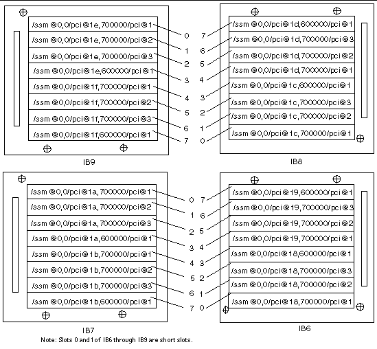
FIGURE A-1 illustrates the Sun Fire E6900 and 6800 PCI I/O assembly physical slot designations for I/O assemblies IB6 through IB9.
FIGURE A-1 Sun Fire E6900 and 6800 PCI Physical Slot Designations for IB6 Through IB9

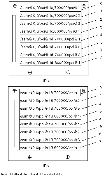
FIGURE A-2 illustrates the comparable information for Sun Fire E4900/4810/4800/3800 systems.
FIGURE A-2 Sun Fire E4900/4810/4800 Systems PCI Physical Slot Designations for IB6 and IB8

CompactPCI I/O Assembly
This section describes the CompactPCI I/O assembly slot assignments and provides an example on the six-slot I/O assembly device paths.
|
 To Determine an I/O Physical Slot Number Using an I/O Device Path To Determine an I/O Physical Slot Number Using an I/O Device Path
|
1. Use TABLE A-6 for Sun Fire 3800 systems or to determine the:
- I/O assembly based on the I/O controller AID address
- Physical slot number based on the I/O assembly and the device path
2. Use FIGURE A-3 to locate the slot based on I/O assembly and the physical slot number.
CompactPCI I/O Assembly Slot Assignments
This code example is the breakdown of the device tree for the CompactPCI I/O assembly, ib8.
/ssm@0,0/pci@1c,700000/pci@1/SUNW,isptwo@4
|
where:
in pci@1c,700000
- c is the I/O controller AID.
- 700000 is the bus offset.
in pci@1
isptwo is the SCSI host adapter.
6-Slot CompactPCI I/O Assembly Device Map
TABLE A-6 lists, in hexadecimal notation, the slot number, I/O assembly name, device path of each I/O assembly, I/O controller number, and bus.
TABLE A-6 Mapping Device Path to I/O Assembly Slot Numbers for Sun Fire 3800 Systems
|
I/O Assembly Name
|
Device Path
|
Physical Slot Number
|
I/O Controller Number
|
Bus
|
|
IB6
|
/ssm@0,0/pci@19,700000/pci@2
|
5
|
1
|
B
|
|
|
/ssm@0,0/pci@19,700000/pci@1
|
4
|
1
|
B
|
|
|
/ssm@0,0/pci@18,700000/pci@2
|
3
|
0
|
B
|
|
|
/ssm@0,0/pci@18,700000/pci@1
|
2
|
0
|
B
|
|
|
/ssm@0,0/pci@19,600000/pci@1
|
1
|
1
|
A
|
|
|
/ssm@0,0/pci@18,600000/pci@1
|
0
|
0
|
A
|
|
IB8
|
/ssm@0,0/pci@1d,700000/pci@2
|
5
|
1
|
B
|
|
|
/ssm@0,0/pci@1d,700000/pci@1
|
4
|
1
|
B
|
|
|
/ssm@0,0/pci@1c,700000/pci@2
|
3
|
0
|
B
|
|
|
/ssm@0,0/pci@1c,700000/pci@1
|
2
|
0
|
B
|
|
|
/ssm@0,0/pci@1d,600000/pci@1
|
1
|
1
|
A
|
|
|
/ssm@0,0/pci@1c,600000/pci@1
|
0
|
0
|
A
|
In TABLE A-6, note the following:
- 600000 is the bus offset and indicates bus A, which operates at 66 MHz.
- 700000 is the bus offset and indicates bus B, which operates at 33 MHz.
- pci@1 is the device number. The @1 means it is the first device on the bus.
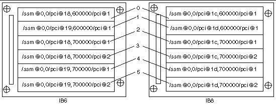
FIGURE A-3 illustrates the Sun Fire 3800 CompactPCI physical slot designations.
FIGURE A-3 Sun Fire 3800 System 6-Slot CompactPCI Physical Slot Designations

4-Slot CompactPCI I/O Assembly Device Map
TABLE A-7 lists, in hexadecimal notation, the slot number, I/O assembly name, device path of each I/O assembly, I/O controller number, and bus for Sun Fire E6900/E4900/6800/4810/4800 systems.
TABLE A-7 Mapping Device Path to I/O Assembly Slot Numbers for Sun Fire E6900/E4900/6800/4810/4800 Systems
|
I/O Assembly Name
|
Device Path
|
Physical Slot Number
|
I/O Controller Number
|
Bus
|
|
IB6
|
/ssm@0,0/pci@19,700000/pci@1
|
3
|
1
|
B
|
|
|
/ssm@0,0/pci@18,700000/pci@1
|
2
|
0
|
B
|
|
|
/ssm@0,0/pci@19,600000/pci@1
|
1
|
1
|
A
|
|
|
/ssm@0,0/pci@18,600000/pci@1
|
0
|
0
|
A
|
|
IB7
|
/ssm@0,0/pci@1b,700000/pci@1
|
3
|
1
|
B
|
|
|
/ssm@0,0/pci@1a,700000/pci@1
|
2
|
0
|
B
|
|
|
/ssm@0,0/pci@1b,600000/pci@1
|
1
|
1
|
A
|
|
|
/ssm@0,0/pci@1a,600000/pci@1
|
0
|
0
|
A
|
|
IB8
|
/ssm@0,0/pci@1d,700000/pci@1
|
3
|
1
|
B
|
|
|
/ssm@0,0/pci@1c,700000/pci@1
|
2
|
0
|
B
|
|
|
/ssm@0,0/pci@1d,600000/pci@1
|
1
|
1
|
A
|
|
|
/ssm@0,0/pci@1c,600000/pci@1
|
0
|
0
|
A
|
|
IB9
|
/ssm@0,0/pci@1f,700000/pci@1
|
3
|
1
|
B
|
|
|
/ssm@0,0/pci@1e,700000/pci@1
|
2
|
0
|
B
|
|
|
/ssm@0,0/pci@1f,600000/pci@1
|
1
|
1
|
A
|
|
|
/ssm@0,0/pci@1e,600000/pci@1
|
0
|
0
|
A
|
In TABLE A-7 note the following:
- 600000 is the bus offset and indicates bus A, which operates at 66 MHz.
- 700000 is the bus offset and indicates bus B, which operates at 33 MHz.
- pci@1 is the device number. The @1 means it is the first device on the bus.
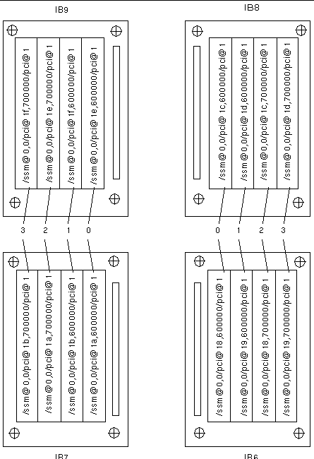
FIGURE A-4 illustrates the Sun Fire E4900/4810/4800 CompactPCI physical slot designations.
FIGURE A-4 Sun Fire E4900/4810/4800 Systems 4-Slot CompactPCI Physical Slot Designations

FIGURE A-5 Sun Fire E6900 and 6800 Systems 4-Slot CompactPCI Physical Slot Designations for IB6 through IB9

| Sun Fire Midrange Systems Platform Administration Manual
|
817-7814-10
|
   
|
Copyright © 2004, Sun Microsystems, Inc. All rights reserved.


