| Sun Fire V890 Server Service Manual |
| Sun Fire V890 Server Service Manual |
| C H A P T E R 3 |
|
Servicing the Input/Output Board Side Components |
This chapter describes how to remove and replace the system input/output (I/O) board and components on the I/O side of the system. For a list of part numbers for field-replaceable units (FRUs) and optional equipment, see Illustrated Parts Breakdown.
The following tasks are covered in this chapter:
All fan trays feature a hot-swap capability. You can remove and replace a faulty fan tray without shutting down the operating system or turning off the system power. However, at least one working I/O fan tray must be present in order to provide proper system cooling. For additional details, see About Hot-Pluggable and Hot-Swappable Components. For more information about I/O fan trays, see About Fan Trays.
If you are not performing a hot-swap procedure, complete the following task:
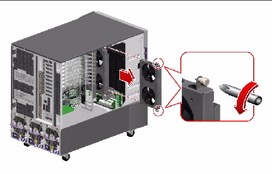
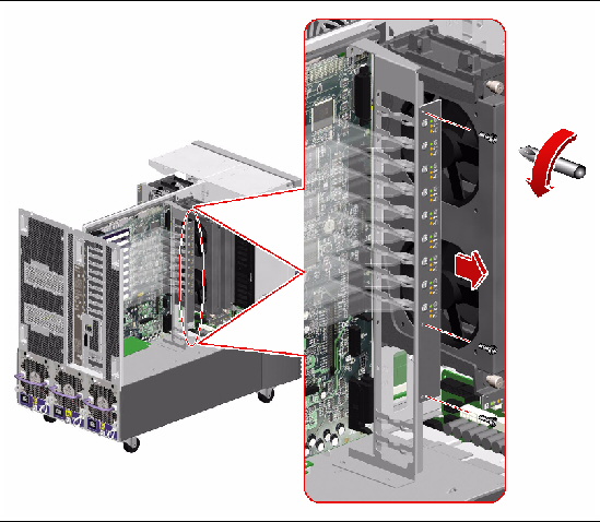
1. Identify the fan tray that you want to remove.
The primary I/O fan tray is in slot 3. For information about I/O fan tray LEDs, see About Fan Tray LEDs.
2. Loosen the two captive Phillips screws securing the fan tray to the brackets.
3. Slide the fan tray out from the brackets.

|
Caution - If you are performing a hot-swap procedure, do not put your hand into the empty fan bay. The fans in the populated fan tray are spinning. |
To replace the I/O fan tray, complete this task:
To reassemble the system, complete this task:
All fan trays feature a hot-swap capability. You can remove and replace a faulty fan tray without shutting down the operating system or turning off the system power. For additional details, see About Hot-Pluggable and Hot-Swappable Components. For more information about I/O fan trays, see About Fan Trays.
If you are not performing a hot-swap procedure, complete the following task:
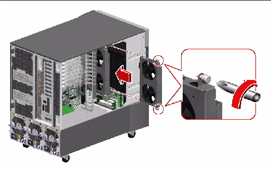
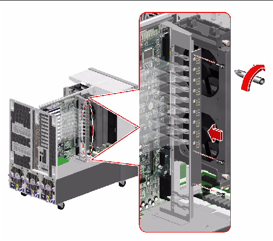
1. Locate the I/O fan tray slot into which you want to install the fan tray.
2. Slide the fan tray into the brackets until the connector on the fan tray is fully seated into its socket.
The label on the I/O fan tray indicates the orientation of the fan tray.

|
Caution - If you are performing a hot-swap procedure, do not put your hand into the empty fan bay. The fans in the populated fan tray are spinning. |
3. Tighten the two captive Phillips screws that secure the fan tray to the brackets.
To reassemble the system, complete this task:
If you installed this part as a new option while the system was powered off, you need to perform a reconfiguration boot. A reconfiguration boot is required in order for the operating system to recognize the new device. See:
PCI cards are hot-pluggable provided the system is running a version of the Solaris Operating System that supports PCI card hot-plug operations. Refer to the Sun Fire V890 Server Product Notes for important information about PCI card hot-plug support.
If you are removing a PCI card as part of a hot-plug procedure, you must perform preliminary software commands to prepare the system before removing the card. In addition, certain other system requirements must be met in order for hot-plug operations to succeed. For more details about PCI card hot-plug procedures and system requirements, see:
|
Note - PCI and disk hot-plug operations are not supported when the system ok prompt is displayed. You can only perform these hot-plug operations while the operating system is running. |
For information about PCI cards, see About PCI Cards and Buses.
If you are not performing a hot-plug procedure, complete the following task:
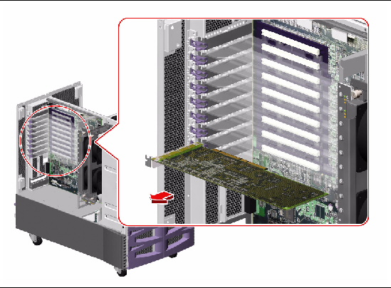
1. Identify the PCI card that you want to remove.
2. Disconnect all external cables connected to the PCI card faceplate.
3. Disconnect all internal cables connected to the PCI card.
4. Pinch the PCI card retaining clip until it releases from the back of the card and rotate the clip outward.
5. Carefully pull the PCI card from the I/O board.
6. Place the PCI card on an antistatic mat.
7. If you are not replacing the PCI card immediately, install a PCI filler panel into the system rear panel.
a. Slide a PCI filler panel into the slot on the system rear panel.
b. Rotate the PCI retaining clip over the back of the filler panel until it snaps into place.
To replace the PCI card, complete this task:
To reassemble the system, complete this task:
If you removed this part while the system was powered off, and you are not replacing the part right away, you need to perform a reconfiguration boot. A reconfiguration boot is required in order for the operating system to recognize the configuration change. See:
PCI cards are hot-pluggable provided the system is running a version of the Solaris Operating System that supports PCI card hot-plug operations. Refer to the Sun Fire V890 Server Product Notes for important information about PCI card hot-plug support.
If you are installing a PCI card as part of a hot-plug procedure, you must perform preliminary software commands to prepare the system before installing the card. In addition, certain other system requirements must be met in order for hot-plug operations to succeed. For more details about PCI card hot-plug procedures and system requirements, see:
|
Note - PCI and disk hot-plug operations are not supported when the system ok prompt is displayed. You can only perform these hot-plug operations while the operating system is running. |
If you are not performing a hot-plug procedure, complete the following task:
1. Identify the slot into which you want to install the PCI card.
2. Remove the PCI filler panel from the back of the system.
a. Pinch the PCI card retaining clip until it releases from the top of the filler panel and rotate the clip outward.
b. Slide the filler panel out from the rear panel.
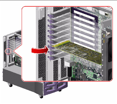
3. Insert the PCI card into the appropriate slot on the I/O board.
If you are installing a PCI long card:
a. Insert the faceplate side of the PCI card into the appropriate opening on the rear panel. At the same time, insert the other end of the card into the corresponding groove on the PCI card bracket.
b. Push the card into the slot on the I/O board until it is fully seated.
If you are installing a PCI short card:
a. Align the faceplate side of the PCI card with the appropriate opening on the rear panel.
b. Push the card into the slot on the I/O board until it is fully seated.
4. Rotate the PCI retaining clip over the back of the PCI card faceplate until it snaps into place.
5. If necessary, connect any internal cables to the PCI card's internal connectors.
6. If necessary, connect any external cables to the PCI card.
To reassemble the system, complete this task:
If you are installing a PCI card as part of a hot-plug procedure, you must issue software commands to reconfigure the operating system after installing the new card. For more details about PCI card hot-plug procedures and system requirements, see
If you installed this part as a new option while the system was powered off, you need to perform a reconfiguration boot. A reconfiguration boot is required in order for the operating system to recognize the new device. See:

|
Caution - The system controller card is not a hot-pluggable component. You must shut down the system and disconnect all the power cords from the system before performing this procedure. |
1. Disconnect the AC power cords from the power supplies.


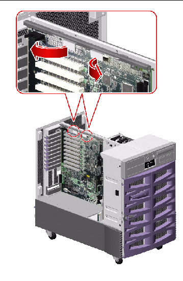
2. Locate the system controller card.
The system controller card is installed in a slot on the system I/O board. It is labeled "SC" on the rear panel.
3. Disconnect any external cables attached to the faceplate of the system controller card.
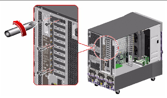
4. Using a Phillips No. 1 screwdriver, remove the screw securing the card to the system rear panel.
5. Pull the system controller card from its slot.
Hold the system controller card by the faceplate and its opposite edge, and pull up while carefully rocking the card from end to end until it is freed from its slot.

|
Caution - Do not apply excessive force to one end or one side of the card. Doing so could damage the card. |
6. Place the system controller card on an antistatic mat.
To replace the system controller card, complete this task:

|
Caution - The system controller card is not a hot-pluggable component. You must shut down the system and disconnect all the power cords from the system before performing this procedure. |
1. Locate the slot for the system controller card, near the bottom of the system I/O board.
Make sure to install the system controller card into the system controller slot (marked "SC" on the rear panel of the server). Although the system controller card can physically fit into a PCI slot, it will not function if installed there.
2. Insert the system controller card into its slot on the system I/O board.
a. Insert the faceplate end of the card into the appropriate opening in the rear panel.
b. Insert the opposite end of the card into the appropriate card guide so that the system controller card is aligned evenly with the connectors on the I/O board.
c. Push the card into the connectors on the system I/O board.
Apply even pressure along the edge of the card.
3. Secure the system controller card faceplate to the rear panel with the Phillips screw.
4. Connect the Ethernet and/or serial cable to the appropriate connector on the system controller card faceplate.
5. Reconnect the AC power cords to the power supplies.
The system controller hardware runs Remote System Control (RSC) software. After replacing the system controller card, you must restore the RSC configuration settings by running the RSC server configuration script. In addition, the replacement card has a new Ethernet MAC address, which may necessitate configuration changes to other network devices. To determine the Ethernet MAC address for the new system controller card, use the RSC shell command shownetwork. For more information, refer to the Remote System Control (RSC) 2.2 User's Guide, which is available on the Sun Fire V890 Documentation CD.
To reassemble the system, complete this task:
For information about FC-AL host adapters, refer to your Sun Fire V890 Server Owner's Guide.
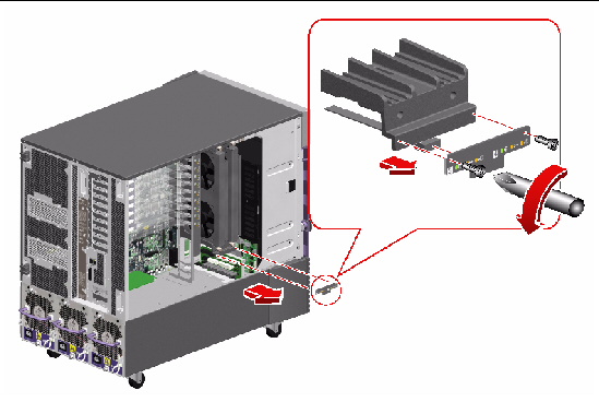
1. Locate the Sun StorEdge PCI Dual Fibre Channel Host Adapter card.
2. Disconnect any internal and external cables attached to the card.
3. Pinch the PCI card retaining clip until it releases from the back of the card and rotate the clip outward.
4. Carefully pull the Sun StorEdge PCI Dual Fibre Channel Host Adapter card from the I/O board.
Hold the card by the faceplate and its opposite edge, and pull up while carefully rocking the card from end to end until it is freed from its slot.

|
Caution - Do not apply excessive force to one end or one side of the card. Doing so could damage the card. |
5. Place the card on an antistatic mat.
6. If you are not immediately replacing the Sun StorEdge PCI Dual Fibre Channel Host Adapter card, install a PCI filler panel into the system rear panel.
a. Slide a PCI filler panel into the slot on the system rear panel.
b. Rotate the PCI retaining clip over the back of the filler panel until it snaps into place.
7. If you are not immediately replacing the card, remove the Sun StorEdge PCI Dual Fibre Channel Host Adapter FC-AL cable from the system.
a. Disconnect the FC-AL cable (D and C) from connectors D and C on the base FC-AL backplane.
b. Remove the cable from the three tie wraps on the chassis power bay.
To replace the Sun StorEdge PCI Dual Fibre Channel Host Adapter card, complete this task:
To reassemble the system, complete this task:
If you are not immediately replacing the Sun StorEdge PCI Dual Fibre Channel Host Adapter card, you need to perform a reconfiguration boot to reflect the new system configuration. For further information, see:
For information about FC-AL host adapters, refer to your Sun Fire V890 Server Owner's Guide.
1. Locate the PCI slot for the Sun StorEdge PCI Dual Fibre Channel Host Adapter card.
|
Note - For optimal performance, install the Sun StorEdge PCI Dual Fibre Channel Host Adapter card into a 66-MHz PCI slot (slot 7 or 8) on the I/O board. The Sun StorEdge PCI Dual Fibre Channel Host Adapter card will function in a 33-MHz or 66-MHz PCI slot. For more information about PCI slots, see About PCI Cards and Buses. |
2. If a PCI filler panel is installed in the slot's rear panel opening, remove it.
a. Pinch the PCI card retaining clip until it releases from the top of the filler panel and rotate the clip outward.
b. Slide the filler panel out from the rear panel.
3. Connect the Sun StorEdge PCI Dual Fibre Channel Host Adapter FC-AL cable to the card.
a. Connect the cable end labeled P3 to connector J3 on the card.
b. Connect the cable end labeled P4 to connector J4 on the card.
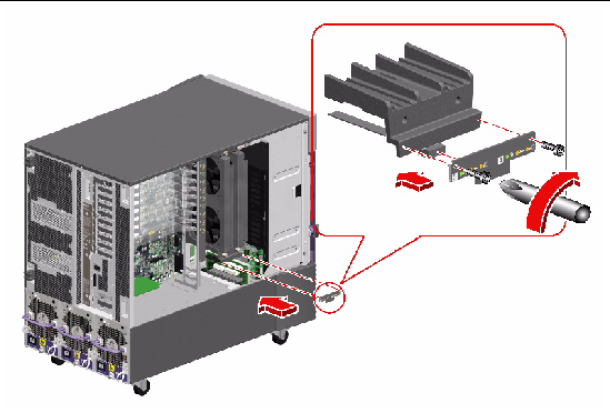
4. Insert the Sun StorEdge PCI Dual Fibre Channel Host Adapter card into its slot on the system I/O board.
a. Insert the faceplate end of the card into the appropriate opening in the rear panel.
b. Push the card into the connectors on the system I/O board.
Apply even pressure along the edge of the card.
5. Rotate the PCI retaining clip over the back of the card faceplate until it snaps into place.
6. If you are installing the card for the first time, route and connect the Sun StorEdge PCI Dual Fibre Channel Host Adapter FC-AL cable in the system in the following manner:
a. Attach the three tie wraps provided with the Sun StorEdge PCI Dual Fibre Channel Host Adapter FC-AL cable onto the lances on the chassis power bay cover.
b. Route the cable down to the chassis power bay cover and through the three tie-wraps.
Leave enough slack in the cable so that you can remove any other installed PCI cards during a PCI hot-plug procedure.
For cable connector locations, see Cable Connector Locations.
c. Connect the cable end labeled D to connector D on the base FC-AL backplane.
d. Connect the cable end labeled C to connector C on the base FC-AL backplane.
To reassemble the system, complete this task:
If you installed this part as a new option, you need to perform a reconfiguration boot in order for the operating system to recognize the new device. See:
1. Disconnect the PCI internal status cable (P37) from the back of the PCI internal LED flex circuit.
2. Remove the three Phillips screws securing the flex circuit to the PCI card bracket and pull the flex circuit from the system.
3. Place the flex circuit on an antistatic mat.
To replace the PCI internal LED flex circuit, complete this task:
1. Align the PCI internal LED flex circuit with the PCI card bracket.
2. Replace the three Phillips screws that secure the flex circuit to the bracket.
3. Connect the PCI internal status cable (P37) to the connector on the back of the flex circuit.
To reassemble the system, complete this task:
1. Disconnect the PCI external status cable (P24) from the back of the PCI external LED flex circuit.
2. Remove the six Phillips screws securing the flex circuit to the rear panel.
3. Remove the flex circuit from the rear panel.
4. Place the flex circuit on an antistatic mat.
To replace the PCI external LED flex circuit, complete this task:
1. Position the PCI external LED flex circuit on the rear panel.
2. Replace the six Phillips screws that secure the flex circuit to the rear panel.
3. Connect the PCI external status cable (P24) to the connector on the back of the flex circuit.
To reassemble the system, complete this task:
1. Disconnect the I/O fan status cable (P27) from the back of the I/O fan LED flex circuit.
2. Remove the two Phillips screws securing the flex circuit to the bottom I/O fan tray bracket.
3. Remove the flex circuit from the system.
4. Place the flex circuit on an antistatic mat.
To replace the I/O fan LED flex circuit, complete this task:
1. Position the I/O fan LED flex circuit on the bottom I/O fan tray bracket.
2. Replace the two Phillips screws that secure the flex circuit to the bracket.
3. Connect the I/O fan status cable (P27) to the connector on the back of the flex circuit.
To reassemble the system, complete this task:
This section explains how to remove a functioning ID PROM module so that you can install it on a new I/O board, thereby preserving the system's host ID information. If you are replacing a defective ID PROM module and want to retain the same host ID and Ethernet address, consult your authorized Sun sales representative or service provider for assistance with programming the new ID PROM with the existing host ID and Ethernet address.
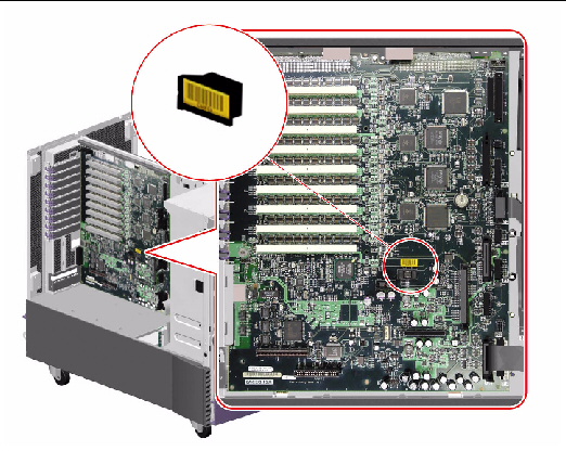
1. Locate the system ID PROM module on the I/O board.
2. Pull the ID PROM module from its socket.
3. Place the ID PROM module on an antistatic mat.
To replace the system ID PROM, complete this task:
This section explains how to install a functioning ID PROM module. If you are replacing a defective ID PROM module and want to retain the same host ID and Ethernet address, consult your authorized Sun sales representative or service provider for assistance with programming the new ID PROM with the existing host ID and Ethernet address.
1. Carefully seat the system ID PROM module into its socket on the I/O board.
The socket is keyed to ensure proper orientation of the ID PROM module.
2. Press evenly and firmly until the ID PROM module is fully seated in the socket.
To reassemble the system, complete this task:

|
Caution - The I/O board is not a hot-pluggable component. You must shut down the system and disconnect all the power cords from the system before performing this procedure. |
You must remove the system controller card and all PCI cards from the I/O board. Note the slot number associated with each card so you can return each card to the appropriate slot when you reassemble the system.
1. Disconnect all AC power cords from the power supplies.
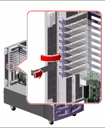
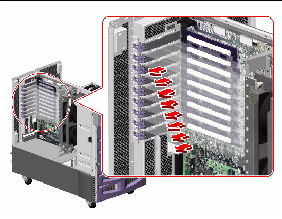
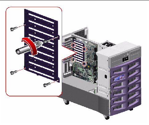
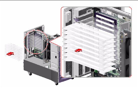
2. Remove the eight PCI card dividers and set them aside.
Hold the divider by the front edge and pull it out from the divider base.
3. Remove the PCI card bracket.
a. Disconnect the PCI internal status cable (P36) from the I/O board at connector J3102(P37).
Keep the cable connected to the flex circuit.
For cable connector locations, see Cable Connector Locations.
b. Remove the four Phillips screws securing the PCI card bracket to the chassis and the I/O board stiffener.
c. Pull the PCI card bracket from the system.
d. Place the bracket on an antistatic mat.
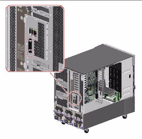
4. Disconnect the following cables from the I/O board:
For cable connector locations, see Cable Connector Locations.
a. DVD-ROM cable (P1) from connector J3402(P1)
b. I2C cable (P18) from connector J3805(P18)
c. System status assembly cable (P32) from connector J3803(P32)
d. Fan power cable from connectors J3804(P6), J3807(P10), and J3806(P3)
e. Fan status cable (P28) from connector J3801(P28)
f. I/O signal cable (P26) from connector J3201(P26)
g. I/O board remote sense cable (P29) from connector J3202(P29)
h. I/O board power cable (P14) from connector J3203(P14)
i. PCI external status cable (P23) from connector J3101(P23)
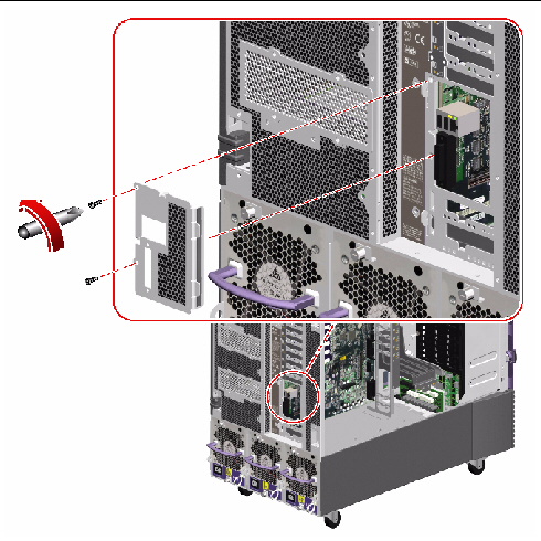
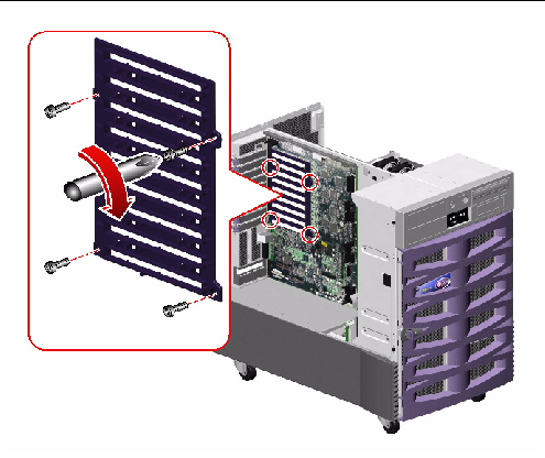
5. Remove the hex standoffs securing the serial port plate to the system rear panel.
6. Remove the serial port plate from the rear panel.
Remove the two Phillips screws securing the plate in the system.
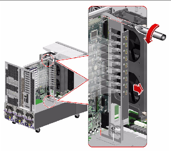
7. Remove the PCI divider card base.
a. Remove the four Phillips screws securing the divider base to the centerplane.
b. Pull the divider base from the system and set it aside.
8. Remove the remaining eight Phillips screws securing the I/O board to the system centerplane.

|
Caution - If the motherboard is not installed, hold the I/O board steady while removing the last few screws to prevent the I/O board from falling out of the system. |
9. If the motherboard is installed, disengage the I/O board from the motherboard by rotating outward the two green ejection levers on the top of the I/O board.
10. Remove the I/O board from the system.
11. Place the I/O board on an antistatic mat.
12. If you are replacing the I/O board with a new one, remove the system ID PROM module from the old I/O board.
See How to Remove the System ID PROM.
To replace the I/O board, complete this task:

|
Caution - The I/O board is not a hot-pluggable component. You must shut down the system and disconnect all the power cords from the system before performing this procedure. |
1. If you are replacing the system I/O board, transfer the system ID PROM module from the old I/O board to the new I/O board.
See How to Install the System ID PROM.

|
Caution - Be sure that the I/O boards are on antistatic mats when you transfer the ID PROM. |
2. Position the I/O board in the system against the centerplane.
Use the pins on the back of the I/O board to align it in the system.
3. If the motherboard is in the system, connect the I/O board to the motherboard connectors by firmly pushing on the I/O board stiffener/ejection assembly.

|
Caution - Do not push on the ejection levers to seat the I/O board in the system. |
4. Replace the eight Phillips screws that secure the I/O board to the centerplane.
a. Insert the top center screw and tighten it by two turns.
b. Insert the screw directly beneath the top center screw and tighten it by two turns.
c. Insert the top left and right screws and tighten them by two turns.
d. Insert the remaining screws and tighten them by two turns.
e. Fully tighten the screws in the pattern described until the board is fully seated.
5. Secure the PCI card divider base to the I/O board with four Phillips screws.
6. Replace the serial port plate on the system rear panel.
Replace the two Phillips screws that secure the plate to the rear panel.
7. Replace the hex standoffs that secure the serial port plate to the system rear panel.
8. Reconnect the following cables to the I/O board:
For cable connector locations, see Cable Connector Locations.
a. I/O board power cable (P14) to connector J3203(P14)
b. I/O board remote sense cable (P29) to connector J3202(P29)
c. I/O signal cable (P26) to connector J3201(P26)
d. Fan status cable (P28) to connector J3801(P28)
e. Fan power cable to connectors J3804(P6), J3807(P10), and J3806(P3)
f. System status assembly cable (P32) to connector J3803(P32)
g. I2C cable (P18) to connector J3805(P18)
h. DVD-ROM cable (P1) to connector J3402(P1)
i. PCI external status cable (P23) to connector J3101(P23)
9. Replace the PCI card bracket.
a. Position the PCI card bracket in the system.
b. Replace the four Phillips screws that secure the PCI card bracket to the chassis and the I/O board stiffener.
c. Connect the PCI internal status cable (P36) to the I/O board at connector J3102(P37).
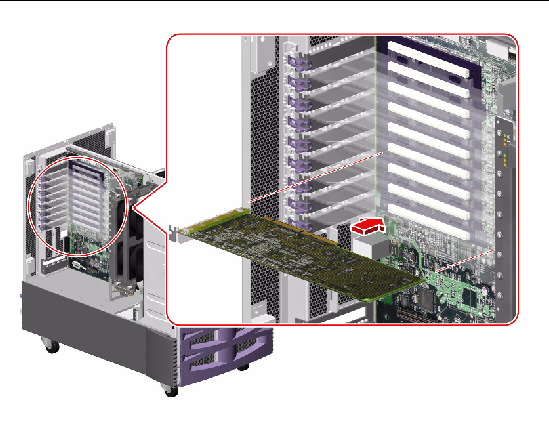
10. Replace the eight PCI card dividers from top to bottom.
a. Carefully align the divider card with its tabs on the divider base.
Ensure that the back end of the divider is over the metal tab on the back of the system and that the plastic tab on the front of the divider is aligned with its slot on the PCI card bracket.
b. Push the card firmly into the tabs on the divider base.
To reassemble the system, complete these tasks:
| Sun Fire V890 Server Service Manual | 817-3957-12 |
Copyright © 2005, Sun Microsystems, Inc. All Rights Reserved.