| Sun Fire V890 Server Service Manual |
| Sun Fire V890 Server Service Manual |
| C H A P T E R 5 |
|
Removing and Installing Miscellaneous Assemblies |
This chapter describes how to remove and install miscellaneous assemblies in the system. For a list of part numbers for field-replaceable units (FRUs) and optional equipment, see Illustrated Parts Breakdown.
The following tasks are covered in this chapter:
|
Note - Use only Sun Fire V890 200-240 VAC power supplies in the Sun Fire V890 system. |
It is not necessary to power off the system if you are removing a redundant power supply. For more information about power supplies, see:
If you are not performing a hot-plug procedure, complete this task:
1. Identify the power supply that you want to remove.
For information about LEDs, see About Power Supply LEDs.
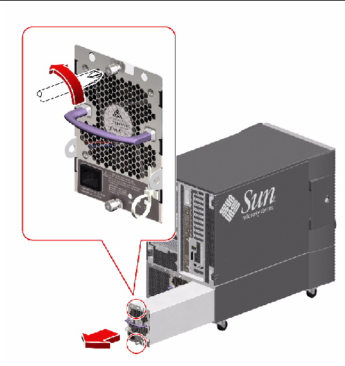
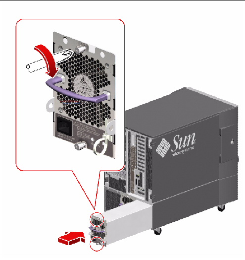
2. Release the AC power cord from the strain-relief tie-wrap on the power supply.
Press the tab on the head of the tie-wrap to release it.
3. Unplug the AC power cord from the power supply and the AC power outlet.
4. Loosen the two captive Phillips screws securing the power supply to the system rear panel.
5. Pull the power supply out from its bay.
Use one hand to pull the power supply out while using the other hand to support the power supply as it is removed from the system.
To replace the power supply, complete this task:
If you are installing a redundant power supply, it is not necessary to shut down and power off the system. For more information, see:
|
Note - Use only Sun Fire V890 200-240 VAC power supplies in the Sun Fire V890 system. |
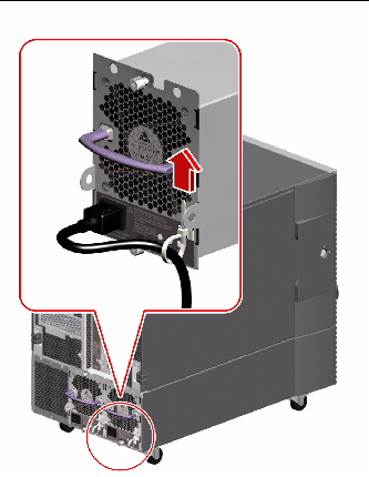
1. Identify the bay into which you want to install the power supply.
For information about LEDs, see About Power Supply LEDs.
2. Slowly slide the power supply into its bay until the connectors on the power supply are fully engaged with the connectors on the power distribution board.
3. Tighten the two captive screws that secure the power supply to the chassis.
4. Connect the AC power cord to both the power supply and a dedicated AC power outlet.
Insert the female end of the power cord through the strain-relief tie-wrap loop located to the right of the supply. Tighten the tie-wrap to secure the connection.
If you installed this part as a new option while the system was powered off, you need to perform a reconfiguration boot. A reconfiguration boot is required in order for the operating system to recognize the new device. See:
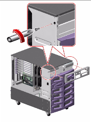
1. Remove the removable media bezel from the system.
Remove the two Phillips screws securing the bezel to the front of the system.
2. Remove the two No. 2 Phillips screws and the three No. 1 Phillips screws securing the system status assembly to the front of the system.
Take care not to damage the flex circuit.
3. Carefully remove the status assembly from the front of the system.
The status assembly is held in place by tabs on the left side and right top of the assembly.
4. Disconnect the system status cable (P31) from the connector on the status assembly.
5. Place the status assembly on an antistatic mat.
To replace the system status assembly, complete this task:
1. Attach the system status cable (P31) to the connector on the side of the system status assembly.
2. Align the status assembly into position on the front of the system.
Insert the tabs on the left side of the status assembly into their cutouts first, as you align the metal tab on the right top side with its cutout.
3. Replace the five Phillips screws that secure the status assembly to the front of the system.
4. Replace the removable media assembly bezel on the front of the system.
Replace the two Phillips screws that secure the bezel to the system front.
To reassemble the system, complete this task:
| Sun Fire V890 Server Service Manual | 817-3957-12 |
Copyright © 2005, Sun Microsystems, Inc. All Rights Reserved.