| Sun Fire V890 Server Rackmounting Guide |
| Sun Fire V890 Server Rackmounting Guide |
| C H A P T E R 3 |
|
Installing the Server Into the Sun Rack 900 Cabinet |
This chapter provides step-by-step instructions for installing the Sun Fire V890 server into the Sun Rack 900 cabinet.
To install a Sun Fire V890 server into the cabinet, complete the following tasks in the order listed:
Before you begin the installation procedures, complete the following tasks:
Adhere to the following cautions when installing a Sun Fire V890 server into the cabinet. For a complete description of the safety cautions to follow when installing a server, see the Sun Fire V890 Server Owner's Guide.

|
Caution - Do not open. Qualified Service Personnel Only. Failure to take this precaution may result in personal injury and system damage. |

|
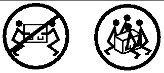
Caution - Do not attempt to lift the server until a qualified service technician removes all CPU/Memory boards, all power supplies, all CPU fan trays, and all I/O fan trays. Once these components are removed, four persons are required to lift the server. See Preparing the Server for information about removing these components. |

|
Caution - To prevent the cabinet from tipping forward, do not attempt to roll or move the cabinet after installing the server in the cabinet. |

|
Caution - For proper ventilation and cooling of the server, be sure the operating location complies with the requirements given in Appendix B. |
The following tools, equipment, and documentation are required when rackmounting the server:
To prepare the server for rackmounting, complete the following tasks:
In order for four persons to lift the server safely, you must reduce the weight of the server before you attempt to install it into the cabinet. To reduce the weight of the server, a qualified service technician should remove the following components:
See the Sun Fire V890 Server Service Manual for component removal procedures.

|
Caution - Do not open. Qualified Service Personnel Only. Failure to take this precaution may result in personal injury and system damage. |
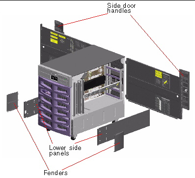
The following figure identifies the parts that you must remove from the chassis before you can install the server into the cabinet.
The following sections provide detailed information about removing each part.
1. Open one of the server's side doors.
Use the key provided with the server to unlock the door.
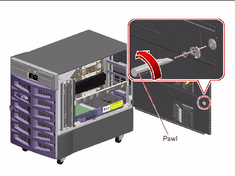
2. Remove the pawl from the side door.
On the inside of the door, remove the slot head screw from the center of the pawl.
Pull the pawl straight out to remove it.
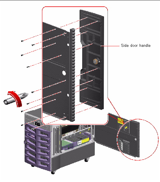
3. Remove the side door handle.
Remove the nine screws from the inside of the door.
From the outside of the door, pull the handle straight out to remove it.
4. Repeat Steps 1 through 3 for the other side door.
5. Place the handles, pawls, and screws into the kit carton for safekeeping.
You will need to reinstall these parts if you reconfigure the server as a deskside unit.
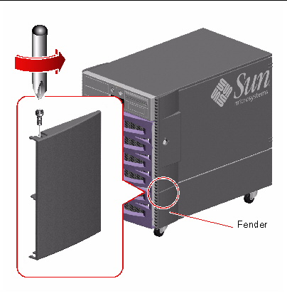
1. Remove the fender from the front of each of the lower side panels.
a. Remove the screw from the top of the fender.
b. Grasp the top and bottom edges of the fender and carefully flex the fender to remove it.
c. Repeat Steps a and b to remove the fender from the other lower side panel.
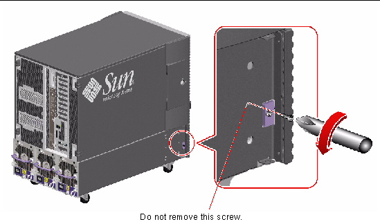
2. Remove the lower side panel from the left side of the server.
Remove the screw located approximately 3 inches (8 cm) from the front of the lower side panel.
|
Note - On the left side of the server, do not remove the screw that attaches the small bracket to the side of the server. Removing this screw prevents the front door from closing securely. |
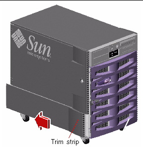
3. Grasp the trim strip and slide the lower side panel toward the rear of the server.
The lower side panel should disengage as you slide the panel so that you can easily remove it.
4. Repeat Steps 2 and 3 for the right lower side panel.
5. Place the fenders, lower side panels, and screws into the kit carton for safekeeping.
You will need to reinstall these parts if you reconfigure the server as a deskside unit.
1. Locate the four lifting handles provided with the rackmounting kit.
2. Install two lifting handles on one side of the server using two M4 screws to attach each handle to the lower side of the server.
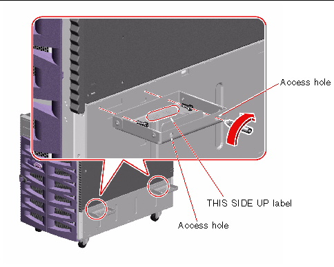
a. With the THIS SIDE UP label facing upward, insert the screwdriver through one of the access holes on the outside of the handle.
Using the access hole makes it easier to reach the screw hole on the inside of the handle.
b. Position the screw on the inside of the handle in the hole that is opposite the access hole.
c. Attach the handle to the server using the appropriate screw hole just below the server side door. See the following figure.
d. Finish installing the handle by repeating the procedure using the second access hole on the outside of the handle.
e. Repeat Steps a through d for the second handle.
3. Repeat Step 2 to install two handles on the other side of the server.
Make sure the operating location complies with the Sun Fire V890 server requirements and cabinet requirements. See Appendix B of this guide and the cabinet documentation for information.
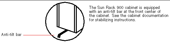
1. Be sure the cabinet is stabilized so that the cabinet cannot move or tip forward.
Stabilize the cabinet by implementing the stabilizing features of the Sun Rack 900 cabinet that are appropriate for your site. See the instructions provided with the Sun Rack 900 cabinet.
2. Open the front and rear doors.
See the instructions provided with the cabinet.
3. Remove (if applicable) the front and rear doors and the side panels of the cabinet.
See the instructions provided with the cabinet.
To install the tray assembly into the cabinet, complete these tasks:
The depth of the Sun Rack 900 cabinet from the outside face of the front rail to the outside face of the rear rail is 27 inches (68.58 cm). The rear brackets will be preset so that the slides fit the depth of the Sun Rack 900 cabinet. However, the rear brackets might need to be adjusted slightly.
If necessary to adjust the rear brackets, perform the following steps:
1. Measure the length of each slide.
Measure the distance from the inside face of the front bracket to the inside face of the rear bracket. If this measurement is longer or shorter than 27 inches (68.58 cm), you must adjust the rear bracket on each slide to accommodate the depth of the cabinet.
2. If required, adjust the rear bracket on each slide.
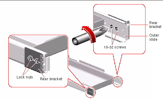
a. Extend the tray assembly until you can see the two 10-32 screws located on the inside rear of each outer slide.
The screws on the inside of the outer slide (and the lock nuts on the outside of the bracket) secure the rear bracket to the outer slide.
b. Loosen the two 10-32 screws and the lock nuts.
c. Slide each rear bracket forward or backward as required to accommodate the depth of the cabinet.
Slide each rear bracket and measure the distance from the inside face of the front bracket to the inside face of the rear bracket.
Continue to slide the rear bracket and measure the distance from the inside face of the front bracket to the inside face of the rear bracket until the measurement equals 27 inches (68.58 cm).
d. Tighten the two 10-32 screws and lock nuts on each slide to resecure the rear brackets to the outer slides.
Plan to install the tray assembly into the lowest available position in the cabinet. If you are installing two Sun Fire V890 servers into the cabinet, install the lower server first.
To determine the vertical position of the server, identify which cabinet rail holes to use for attaching the front and rear brackets by completing the following steps:
1. Locate and mark the correct holes on the right and left front vertical cabinet rails.
Make sure there is enough vertical space to install the server.
|
Note - Each Sun Fire V890 server requires 17 rack units (29.75 inches, 75.6 cm) or 51 holes on the vertical rails of the cabinet. The Sun Rack 900 cabinet can accommodate two Sun Fire V890 servers. |
If your Sun Rack 900 cabinet is equipped with the Sun Power Distribution System (PDS) option and the Sun Fire V890 server will be installed immediately above the two power sequencers provided by the Sun PDS option, the Sun Fire V890 server can be installed using the first rail hole to attach the front and rear brackets.
If your Sun Rack 900 cabinet is equipped with a third-party PDS or power sequencers and the Sun Fire V890 server will be installed immediately above the third-party PDS or power sequencers, leave at least one free hole above the PDS or sequencers.
Using masking tape or a felt tip pen, mark the lowest available hole for installing the tray on the right front vertical rail of the cabinet.
Mark the matching hole on the left front rail of the cabinet. Count the holes to be sure you are using matching holes on the right and left rails of the cabinet.
2. Locate and mark the corresponding holes on the right and left rear vertical cabinet rails.
Using masking tape or a pen, mark the matching holes on the right and left rear vertical rails.
Count the holes to be sure you are using the holes that match the ones you marked in Step 1.
Using the rail holes you marked in Determine the Vertical Position of the Server in the Cabinet, attach the tray assembly to the cabinet by completing the following steps:
1. Attach the front brackets on the slides of the tray assembly to the front rails of the cabinet.
a. With the help of an assistant, position the tray assembly on the inside of the cabinet with the front brackets at the front of the cabinet.
To fit the tray assembly between the rails, you will need to tilt it by lowering one side of the assembly.
b. Attach the front brackets to the front rails of the cabinet using four M6 screws.
Align the lower hole of each front bracket with the front rail holes you marked in Determine the Vertical Position of the Server in the Cabinet.
Secure the front brackets using one M6 screw in the lower hole of each bracket. Finger-tighten the screws.
Align the upper hole of each front bracket with the corresponding hole in the cabinet rail. Secure the brackets to the rails using one M6 screw in each upper hole. Finger-tighten the screws.
Do not tighten the screws completely until all the screws are in place and the tray assembly is level.
2. Attach the rear brackets to the rear rails of the cabinet using four M6 screws.
Align the lower hole of each rear bracket with the rail hole you marked in Determine the Vertical Position of the Server in the Cabinet.
Secure the brackets using one M6 screw in each lower hole. Finger-tighten the screws.
Align the upper hole of each rear bracket with the coinciding hole in the cabinet rail. Secure the brackets to the rails using one M6 screw in each upper hole. Finger-tighten the screws.
Do not tighten the screws completely until all the screws are in place and the tray assembly is level.
3. Make sure the tray assembly is level.
Use a level to ensure the tray assembly is level front-to-back and left-to-right.
4. Once the tray assembly is level, completely tighten all of the bracket screws.
Tighten the eight M6 screws that secure the front and rear brackets to the vertical cabinet rails.
5. Slide the tray assembly in and out of the cabinet to be sure the slides operate smoothly.
1. Be sure the cabinet is stabilized so that the cabinet cannot move or tip forward when the tray is extended and the server is placed on the tray.
Stabilize the cabinet by implementing the stabilizing features of the Sun Rack 900 cabinet that are appropriate for your site. See the instructions provided with the Sun Rack 900 cabinet to implement the stabilizing features.

|
Caution - Before you slide the tray out, be sure the cabinet is stabilized so that it cannot move or tip forward. See the cabinet documentation for information about stabilizing the cabinet. |

|
Caution - Do not attempt to lift the server until a qualified service technician removes all CPU/Memory boards, all power supplies, all CPU fan trays, and all I/O fan trays. Once these components are removed, four persons are required to lift the server. See Preparing the Server for information about removing these components. |
2. Extend the tray all the way forward.
Standing in front of the cabinet, grasp the tray handle and pull the tray toward you until it stops.

|
Caution - Do not place your fingers on the tray or under the server while you are lifting the server and positioning it on the tray. |
3. Place the server on the tray.
a. Lift the server (two persons on each side of the server) using the lifting handles that you installed in Install the Lifting Handles.
b. Position the server on the tray so that the front of the server is at the front of the tray and the back of the server is at the back of the tray.
4. Adjust the server on the tray until the four holes on each side of the server align with the four holes in the tray assembly.
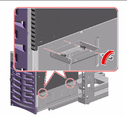
5. Remove the four lifting handles from the sides of the server.
a. Insert the screwdriver through one of the access holes on the outside of the handle.
Using the access hole makes it easier to reach the opposite screw hole on the inside of the handle to remove the screw. See the following figure.
b. Remove the two M4 screws that attach each handle to the server.
c. Save the eight M4 screws you remove.
You will need to use the screws in Step 7.
6. Secure the handles to the rack for safekeeping.
You must reattach the handles if you need to remove the server from the cabinet.
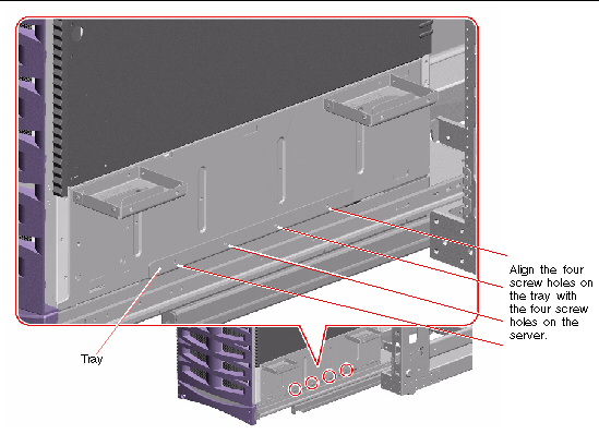
7. Secure the server to the tray assembly using the eight M4 screws you removed in Step 5.
Use four M4 screws on each side of the server as shown in the following figure.
Do not tighten the screws until all screws are in place and you check the placement of the server.
8. Check that the server is level and centered on the tray.
Use a level and adjust the server position if necessary.
9. Tighten the eight M4 screws that secure the server to the tray assembly.
1. A qualified service technician must install the CPU/Memory boards and fan trays that were removed before you installed the server into the cabinet.
See the Sun Fire V890 Server Service Manual for installation instructions.
2. If you removed the server's side doors, replace them.

|
Caution - Avoid keeping the server's doors open for extended periods while the system is operating. Server doors must be closed to prevent automatic thermal shutdown. |
3. Close both of the server's side doors securely.
4. Slide the tray assembly into the cabinet.
5. Install the power supplies that you removed before you installed the server into the cabinet.
See the Sun Fire V890 Server Service Manual for installation instructions.
To secure the tray assembly and server in the cabinet, attach the tray handle to the front rails of the cabinet.
1. Attach the tray handle to the front rails of the cabinet.
Use one or two M6 screws to attach the tray handle to each front rail.
If each of the two screw holes on each side of the handle aligns with a rail hole, use two M6 screws to attach each side of the tray handle to each front rail as shown in the following figure.
If only one screw hole on each side of the handle aligns with a rail hole, use one M6 screw to attach each side of the tray handle to each front rail.
2. Locate the Sun Fire V890 server key.
3. Lock the system in the cabinet.
Insert the Sun Fire V890 server key into the keylock on the tray handle and turn the key 90 degrees counterclockwise.
Locking the tray handle extends the security plates so that they cover the screw heads on each side of the tray handle. The security plates prevent removal of the screws that secure the tray and the server to the cabinet.
4. Remove and safeguard the key.
1. Replace the front and back doors of the cabinet, if applicable.
See the instructions provided with the cabinet.
2. If you removed the side panels from the cabinet, do not replace them until you connect and route the server cables.

|
Caution - To prevent the cabinet from tipping forward, do not attempt to roll or move the cabinet after installing the server in the cabinet. |
Connect the server power cords, network cables, and I/O interface cables to the server and route the cables, allowing enough slack for service access. See "How to Install the Sun Fire V890 Server" in the Sun Fire V890 Server Owner's Guide.
| Sun Fire V890 Server Rackmounting Guide | 817-6264-10 |
Copyright © 2004, Sun Microsystems, Inc. All rights reserved.