| C H A P T E R 2 |
|
Physical Specifications |
This chapter describes the physical specifications and accessibility considerations for Sun Fire V1280/Netra 1280 systems. It contains the following sections:
The depth given on TABLE 2-1 does not include I/O connectors, power connectors, or cable management features.
Cables are likely to protrude a minimum of 1.2 in. (3 cm) from the rear of the system, and the telescopic slides protrude 1.1 in. (2.8 cm). The cable management arm could add between 2.4 in. to 7.9 in. (6 cm to 20 cm) to the system depth.
Power connectors could add 2 in. (5 cm) to the depth.
TABLE 2-1 shows the shipping dimensions of a Sun Fire V1280/Netra 1280 system.
|
Opening in wooden pallet to accommodate lifting device
|
||||
|
Opening in orange mounting cradle to accommodate lifting device |
||||
Sun Fire V1280/Netra 1280 systems have been designed to accommodate the most common mounting configurations. The rackmount kit that ships with the system allows installation in the following racks:
An optional rackmount kit provides adapters to allow installation in a 23-inch two-post rack with a post depth of 5 inches (12.70 cm). These are intended for use with Telco unequal flange seismic frames.
Sun Fire V1280/Netra 1280 systems must be mounted using screws suitable for the equipment rack. The screws should be M5, M6, or no. 10-32 UNF (unified bolt threads fine). All screws must be fitted. The recommended tightening torque value for either M5 or no. 10-32 UNF recess head screws is 2.8 lb-f (3.8 N m), and that for M6 screws is 4.4 lb-f (6 N m).
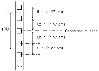
The vertical mounting hole pattern of the rack should conform to the standard dimensions shown in FIGURE 2-1.

Ensure that the slides will fit the RETMA hole pattern so that the system, when installed, aligns with a RU (rack unit) boundary.
Sun Fire V1280/Netra 1280 systems occupy 12 RU (21 in./53.34 cm) of vertical height.
There must be a minimum of 22.44 inches (57.00 cm) usable internal depth in the rack or cabinet.
Required usable depth (rack internal space) is dependant upon the cooling airflow arrangement and the type of cable management used.
The cable management arm (CMA) must not be installed, and the front cabinet door must be removed (to provide maximum airflow) to achieve the minimum depth (cable support must be provided by the installer).
The CMA-lite cable management arm must be installed, and the front cabinet door must be ventilated with 1 inch (2.50 cm) of air plenum to achieve the typical lite depth.
The CMA-800 cable management arm must be installed, and the front cabinet door must be ventilated with 1 inch (2.50 cm) of air plenum to achieve the typical depth.
The CMA-800 cable management arm must be installed, and the front cabinet door must be solid with a 3.54 inch (9.00 cm) plenum at the front of the system to act as a ventilation chimney. An inset to the front mounting rails of 4.5 inches. (11.50 cm) is required.
The rack must be capable of supporting a static load of 236 pounds (107 kg) for each fully configured Sun Fire V1280/Netra 1280 system installed. Dynamic load considerations are subject to site location and application specifications.
In a suitably stable four-post rack, two Sun Fire V1280/Netra 1280 systems can be fitted. Mounting hole information is provided in the Sun Fire V1280/Netra 1280 Systems Installation Guide.
No units or cables above or below a system should protrude beyond the front of the system to ensure system access when the slides are extended.

|
Sun strongly suggests that all host cabinets containing a Sun Fire V1280/Netra 1280 system be anchored to the floor, to the ceiling, or to adjacent frames, using the manufacturer's instructions.
Free standing cabinets should be supplied with an anti-tilt feature, which must sufficiently support the weight of the Sun Fire V1280/Netra 1280 system when extended on its slides (usually a minimum of 10.6 inches (27 cm) from the front edge of the rack). Where an anti-tilt feature is not supplied and the cabinet is not bolted to the floor, a safety evaluation must be conducted by the installation or service engineer to determine rack stability when the Sun Fire V1280/Netra 1280 system is extended on its slides.
Prior to installing the cabinet on a raised floor, a safety evaluation must be conducted by the installation or service engineer to ensure that the floor has sufficient strength to handle the Sun Fire V1280/Netra 1280 system when extended on its slides. In this case secure the rack through the raised floor to the concrete floor below using a proprietary rack-mounting kit for the purpose.

|
Caution - When multiple systems are fitted in a cabinet, only one system can be extended for service at any a time. |
When determining the final location of the Sun Fire V1280/Netra 1280 system, ensure there is enough space for service access. Allow a minimum of clearance of 35 inches (86.0 cm) at the front and rear of the system for service access.
The distance between cabinets can be zero. The last cabinet within any aisle should be a minimum of 36 inches (91.4 cm) from any data center equipment or dividing walls.
|
Note - Additional room on the right side of the system is desirable to improve access for I/O and IB-SSC service. |
If the Sun Fire V1280/Netra 1280 system is used in an environment where Earthquake Zone 4 compliance is required, a rack designed to tolerate a Zone 4 earthquake must be selected, and independent tests undertaken to ensure system compliance in these areas.
A seismic rack should be rigid enough to result in a fundamental resonance in the horizontal axis of greater than 5 Hz with the Sun Fire V1280/Netra 1280 system installed.
Copyright © 2006, Sun Microsystems, Inc. All Rights Reserved.