| C H A P T E R 4 |
|
Removing and Replacing Rotating Service Module Components |

|
Caution - The procedures in this section are for qualified service engineers only. |

|
Caution - Before carrying out any of the procedures in this chapter, read Avoiding Electrostatic Dischargeand wear a properly grounded antistatic strap. |
|
Note - Illustrations may contain optional components that are not available on all standard configurations of the Netra 240 server. |
This chapter provides removal and replacement procedures for the following components:
The alarm board is an LED card with four alarm indicators that is mounted on the rotating service module. The user can reset or apply various applications to the system by configuring the alarm indicator states.
See Removing the Server Cover.
3. Open the rotating service module.
See Opening the Rotating Service Module.
4. Ensure that the server is properly grounded.
See Avoiding Electrostatic Discharge.
5. Push back the securing tabs and detach the ribbon cable and the cable to the SCSI board (FIGURE 4-1).
6. Using a No. 2 Phillips screwdriver, loosen the green captive screw that secures the alarm board to the rotating service module (FIGURE 4-1).
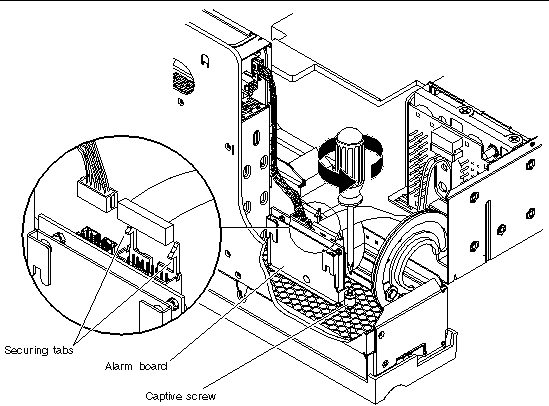
7. Lift the alarm board up and out of the server.
1. Place the alarm board into position in the rotating service module (FIGURE 4-1).
2. Tighten the captive screw to secure the alarm board to the rotating service module (FIGURE 4-1).
3. Connect the ribbon cable and the cable to the SCSI board to the alarm board and set the securing tabs (FIGURE 4-1).
4. Close the rotating service module.
See Closing the Rotating Service Module.
See Installing the Server Cover.
The front fan assembly tray is located behind the rotating service module. The front fan assembly tray contains two fans, F2 and F3. The entire front fan assembly tray should be replaced if one of these fans fail.
See Removing the Server Cover.
3. Open the rotating service module.
See Opening the Rotating Service Module.
4. Ensure that the server is properly grounded.
See Avoiding Electrostatic Discharge.
5. Detach the two front fan assembly cables from the system board connectors (FIGURE 4-2).
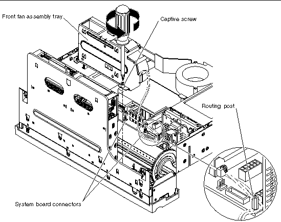
6. Using a No. 2 Phillips screwdriver, loosen the green captive screw that secures the front fan assembly tray to the rotating service module (FIGURE 4-2).
7. Lift the front fan assembly tray straight up and remove it from the server (FIGURE 4-2).
1. Place the front fan assembly tray into position in the rotating service module (FIGURE 4-2).
2. Tighten the captive screw to secure the front fan assembly tray to the rotating service module (FIGURE 4-2).
3. Connect the two cables to the system board and route it behind the post (FIGURE 4-2).
|
Note - Refer to the chassis label for an illustration of the correct routing of the cables. |
4. Close the rotating service module.
See Closing the Rotating Service Module.
See Installing the Server Cover.
The SCSI interface board houses the two hard drives.
2. Grip the bezel at the two finger holds and rotate it down to its open position (FIGURE 2-4).
3. Make a note of which drive bay holds each hard drive.
You remove the hard drives in the next step. However, you want to install the hard drives back into the same slots that you removed them from at the end of this procedure.
4. Remove the hard drives from the drive bays.
See Removing the Server Cover.
6. Open the rotating service module.
See Opening the Rotating Service Module.
7. Ensure that the server is properly grounded.
See Avoiding Electrostatic Discharge.
8. Using a No. 2 Phillips screwdriver, loosen the green captive screw on the top of the SCSI interface board (FIGURE 4-3).
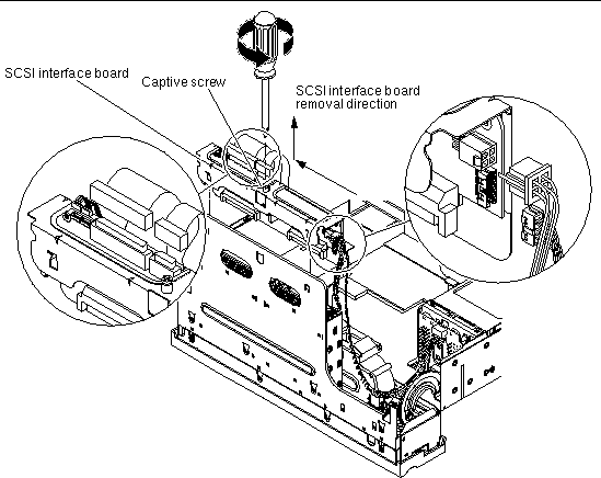
9. Detach the bezel cables, the SCSI interface cable, the DVD power/I2C interface ribbon cable, the alarm board cable, and the SCSI interface board power cable from the SCSI interface board (FIGURE 4-3).
10. When standing in the front of the server, slide the SCSI interface board to the left and then up to remove it from the rotating service module.
1. When standing in the front of the server, place the SCSI interface board into position in the rotating service module (FIGURE 4-3).
Align the six tabs on the SCSI interface board, then slide the assembly down and to the right to lock into position.
2. Tighten the captive screw to secure the board to the rotating service module (FIGURE 4-3).
3. Attach and route the bezel cables, the SCSI interface cable, the DVD power/I2C interface ribbon cable, the alarm board cable, and the SCSI interface board power cable to the SCSI interface board (FIGURE 4-3).
4. Close the rotating service module.
See Closing the Rotating Service Module.
See Installing the Server Cover.
6. Grip the bezel at the two finger holds and rotate it down to its open position (FIGURE 2-4).
7. Install the hard drives back into the drive bays.
See Installing a Hard Drive. Refer to the notes that you took earlier in the procedure to install the hard drives back into the proper bays.
The system configuration card reader cluster includes the DVD drive bay, the rotary switch, and the system configuration card bay.
2. Grip the bezel at the two finger holds and rotate it down to its open position (FIGURE 2-4).
3. Remove the system configuration card from the system configuration card reader.
See Removing a System Configuration Card.
4. Remove the DVD-ROM drive from the server.
See Removing a DVD Drive.
See Removing the Server Cover.
6. Open the rotating service module.
See Opening the Rotating Service Module.
7. Ensure that the server is properly grounded.
See Avoiding Electrostatic Discharge.
8. Lift the SCSI/IDE cable clamp out of the way (FIGURE 4-4).
The clamp has a green cap that is attached to the chassis, and holds the SCSI interface cable and the IDE cable.
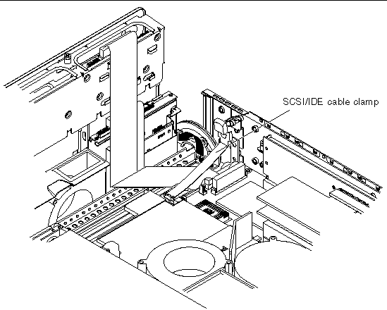
9. Unplug the cables in the sequence below (FIGURE 4-5 and FIGURE 4-6):
a. Unplug the SCSI interface board cable from the system board and remove it out of the way.
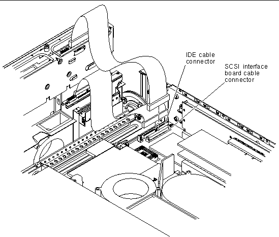
b. Unplug the IDE cable from the system board and leave the cable attached at the other end (FIGURE 4-5).
c. Unplug but do not remove the DVD power/I2C interface ribbon cable from the SCSI interface board.
d. Unplug the bezel cables from the SCSI interface board and move them out of the way.
10. Using a No. 2 Phillips screwdriver, loosen the two green captive screws at the front of the system configuration card reader cluster (FIGURE 4-6).
11. Grasp the system configuration card reader cluster on the two green grip points, lift up and remove (FIGURE 4-6).
The grip points are visible when viewed from the top of the system configuration card reader cluster with the rotating service module open.
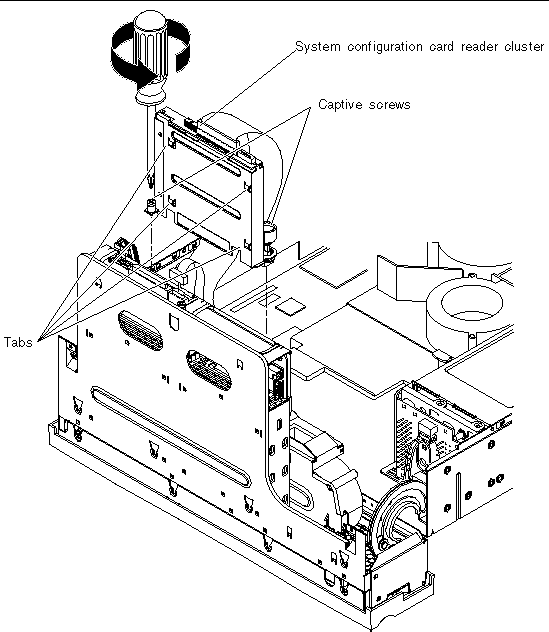
1. Place the system configuration card reader cluster in position in the rotating service module (FIGURE 4-6).
Ensure that the four tabs are properly inserted into their locations.
2. Using a No. 2 Phillips screwdriver, tighten the two captive screws to secure the cluster to the rotating service module (FIGURE 4-6).
a. Plug the IDE cable into the system board.
b. Plug the bezel cables into the SCSI interface board.
c. Plug the DVD power/I2C interface ribbon cable into the SCSI interface board.
d. Plug the SCSI interface cable.
4. Press the SCSI/IDE cable clamp back down to secure the SCSI interface and IDE cables.
The cable clamp is attached to the chassis and has a green cap. See FIGURE 4-4 for the location of this clamp.
5. Close the rotating service module.
See Closing the Rotating Service Module.
See Installing the Server Cover.
7. Grip the bezel at the two finger holds and rotate it down to its open position (FIGURE 2-4).
8. Install the DVD drive back into the server.
9. Install the system configuration card back into the system configuration card reader.
See Inserting a System Configuration Card.
Copyright © 2005, Sun Microsystems, Inc. All Rights Reserved.