| C H A P T E R 3 |
|
Mounting the Chassis in a Rack |
This chapter provides instructions for mounting the chassis in a rack. This chapter contains the following topics:
The Netra CT chassis fits into a standard 19-inch width rack. Note that you can move the standard mounting brackets up to six inches (152.4 mm) backward on the Netra CT chassis to center-mount the chassis (FIGURE 3-1).
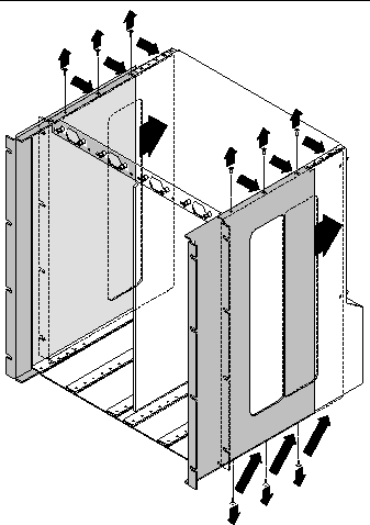
Determine the appropriate action:
|
1. Obtain the mounting bracket adapters from the shipping kit.
2. Place one of the mounting bracket adapters behind the right chassis mounting bracket, and align the holes in the adapter with the mounting bracket (FIGURE 3-2).
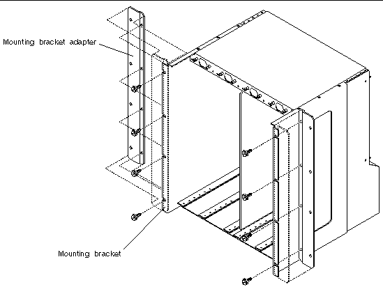
3. Secure the mounting bracket adapter to the mounting bracket using four screws from the shipping kit.
4. Repeat Step 2 and Step 3 to secure the left mounting bracket adapter to the chassis.
The Netra CT chassis is shipped with one to four Netra CT servers installed inside. A fully loaded Netra CT chassis, including the rackmounting brackets, weighs 150 pounds (68 kg). To mount a fully loaded chassis into a rack, you must use a lifting device, or two persons, to lift the chassis.
Alternatively, you can remove all the servers from the chassis to make the chassis lighter before you mount it in the rack. An empty chassis (with all servers removed) weighs 74 pounds (33.6 kg).
|

|
Caution - Do notattempt to remove a server from the chassis without first performing the next step or you might damage major system components. |
1. Unseat all the rear transition modules (RTMs) from the server that you are going to remove.
You do not have to completely remove the RTMs from the chassis; just pull them out an inch or two so that they are disengaged from the rear of the server.
2. Using a No. 2 Phillips screwdriver, loosen the black captive screws at the top of the server.
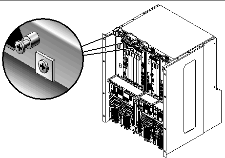

3. Using a No. 2 Phillips screwdriver, loosen the black captive screws at the bottom of the server.

|
Caution - Do not loosen the silvercaptive screws at the base of the server; those screws hold the power supply unit in place. |
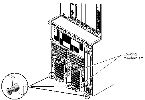
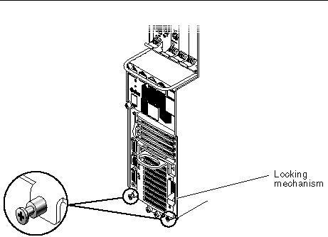
4. Push the power supply unit locking mechanism up into the unlocked ( )position.
FIGURE 3-5 shows the location of the two power supply unit locking mechanisms on the Netra CT 810 server, and FIGURE 3-6 shows the location of the single power supply unit locking mechanism on the Netra CT 410 server. Make sure you unlock both power supply units if you are replacing an Netra CT 810 server, or you will not be able to remove the server from the chassis.
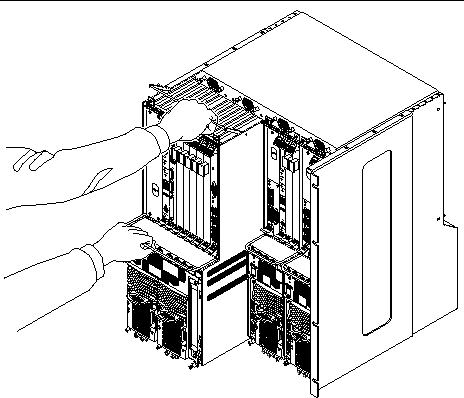
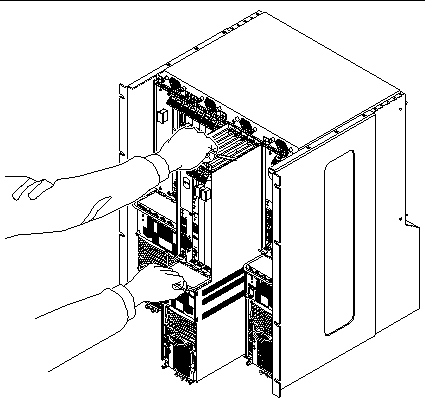
5. With your left hand, grasp the bar in front and slowly pull the server out of the chassis until the purple handle at the top of the server is visible.
6. With your right hand, grasp the purple handle at the top of the server, and completely pull the server out of the chassis using both the bar in front and the handle at the top.
FIGURE 3-7 shows how to remove a Netra CT 810 server from the chassis, and FIGURE 3-8 shows how to remove a Netra CT 410 server from the chassis.
7. Place the server on a flat level surface, taking care not to damage the metal lip that extends from the bottom of the server.
|

|
Caution - Ensure that the rack is bolted to the floor before you install the chassis in the rack. |
1. Raise the Netra CT chassis to the appropriate height in the rack, then align the mounting holes on the sides of the chassis with the mounting holes in the rack rails (FIGURE 3-9).
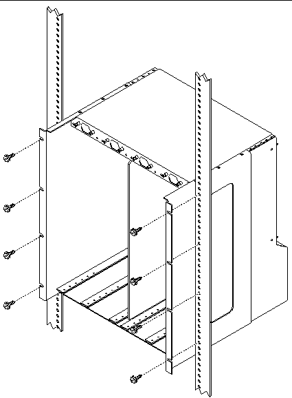
2. Secure the chassis to the rack using eight screws (four on each side).
|
See Supply and Ground Conductor Requirements for the site requirements.
1. Get a DC grounding cable and two M5 nuts with lock washers.
2. Go to the rear of the chassis and locate the two DC grounding studs.

3. Remove the plastic shielding from the DC grounding studs.
4. Position and align the DC grounding cable against the two DC grounding studs at the rear of the chassis.
5. Place the star washers between the DC grounding cable and the two nuts that you use to secure one end of the grounding cable to the two studs.
6. Tighten the two nuts to secure the grounding cable to the two studs.
7. Secure the other end of the grounding cable to the earth ground in the building.
You can secure the grounding cable to a proper grounding point on the rack, as long as the rack is properly grounded to the earth ground in the building.

|
Caution - If energized units are not properly grounded, an energy hazard is present. |
8. Install the servers in the Netra CT chassis, if necessary.
Copyright © 2007, Sun Microsystems, Inc. All Rights Reserved.