| C H A P T E R 2 |
|
Preparing to Service the System |
This chapter contains the following sections:
Be sure to keep the following guidelines in mind when servicing the system:
The following tools are required to install and service the system:
The last two items help protect the system against damage due to electrostatic discharge. For more information, see Avoiding Electrostatic Discharge.
Refer to the following sections to power the server on and off:
Refer to the following sections to power on the system either locally or remotely:
Do not use this power-on procedure if you have just added any new internal option or external storage device, or if you have removed a storage device without replacing it. To power on the system under those circumstances, you must initiate a reconfiguration boot. For those instructions, see Initiating a Reconfiguration Boot .

|
Caution - Never move the system when the system power is on. Movement can cause catastrophic hard drive failure. Always power off the system before moving it. |

|
Caution - Before you power on the system, ensure that the system doors and all panels are properly installed. |
1. Turn on power to any external peripherals and storage devices.
Read the documentation supplied with the device for specific instructions.
2. Establish a connection to the system console.
If you are powering on the system for the first time, connect a device to the serial management port using one of the methods described in the Netra 440 Server Installation Guide. Otherwise, use one of the methods for connecting to the system console, also described in the Netra 440 Server Installation Guide.
3. Connect the AC or DC power cables.
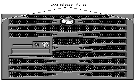
4. Press the door release latches and lower the system door.

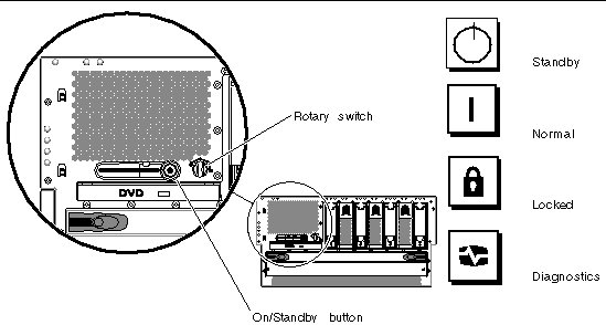
5. Turn the rotary switch to the Normal or Diagnostics position (FIGURE 2-2).

6. Press and release the On/Standby button to power on the system (FIGURE 2-2).
The power supply Power OK LEDs light when power is applied to the system. Verbose (POST) output is immediately displayed to the system console if diagnostics are enabled at power-on, and the system console is directed to the serial and network management ports.
The system can take anywhere from 30 seconds to 20 minutes before text messages appear on the system monitor (if one is attached) or the system prompt appears on an attached terminal. This time depends on the system configuration (number of CPUs, memory modules, PCI cards, and console configuration) and the level of POST and OpenBoot Diagnostics tests being performed. The System Activity LED lights when the server is running under control of the Solaris OS.
7. Turn the rotary switch to the Locked position (FIGURE 2-2).
This prevents anyone from accidentally powering off the system.
Do not use this power-on procedure if you have just added any new internal option or external storage device, or if you have removed a storage device without replacing it. To power on the system under those circumstances, you must initiate a reconfiguration boot. For those instructions, see Initiating a Reconfiguration Boot .
To issue software commands, you need to set up an alphanumeric terminal connection, a local graphics monitor connection, ALOM connection, or a TIP connection to the Netra 440 server. See the Netra 440 Server Installation Guide for more information about connecting the Netra 440 server to a terminal or similar device.

|
Caution - Before you power on the system, ensure that the system doors and all panels are properly installed. |

|
Caution - Never move the system when the system power is on. Movement can cause catastrophic hard drive failure. Always power off the system before moving it. |
Refer to the Advanced Lights Out Manager Software User's Guide for the Netra 440 Server (817-5481-xx) for more information.
2. Type the following command:
Refer to the following sections to power off the system either locally or remotely:
1. Notify users that the system will be powered down.
2. Back up the system files and data, if necessary.
4. Ensure that the rotary switch is in the Normal or Diagnostics position (FIGURE 2-2).
5. Press and release the On/Standby button (FIGURE 2-2).
The system begins a graceful software system shutdown.
6. Wait for the system to power off.
The power supply Power OK LEDs go out when the system is powered off.
7. Turn the rotary switch to the Standby position (FIGURE 2-2).
To issue software commands, you need to set up an alphanumeric terminal connection, a local graphics monitor connection, ALOM connection, or a TIP connection to the Netra 440 server. See the Netra 440 Server Installation Guide (817-3882-xx) for more information about connecting the Netra 440 server to a terminal or similar device.
You can power off the system remotely either from the ok prompt or from the ALOM sc> prompt.
1. Notify users that the system will be powered off.
2. Back up the system files and data, if necessary.
Refer to the Netra 440 Server System Administration Guide (817-3884-xx) for more information, if necessary.
4. Issue the following command:
1. Notify users that the system will be powered off.
2. Back up the system files and data, if necessary.
Refer to the Advanced Lights Out Manager Software User's Guide for the Netra 440 Server (817-5481-xx) for more information.
4. Issue the following command:
After installing any new internal option or external storage device, you must perform a reconfiguration boot so that the operating system is able to recognize the newly installed device(s). In addition, if you remove any device and do not install a replacement device prior to rebooting the system, you must perform a reconfiguration boot in order for the operating system to recognize the configuration change. This requirement also applies to any component that is connected to the system I2C bus to ensure proper environmental monitoring.
This requirement does not apply to any component that is:
To issue software commands, you need to set up an alphanumeric terminal connection, a local graphics monitor connection, ALOM connection, or a TIP connection to the Netra 440 server. See the Netra 440 Server Installation Guide (817-3882-xx) for more information about connecting the Netra 440 server to a terminal or similar device.

|
Caution - Before you power on the system, ensure that the system doors and all panels are properly installed. |
This procedure assumes that you are accessing the system console using the serial management or network management port.
For more information, refer to the Netra 440 Server Administration Guide (817-3884-xx).
1. Turn on power to any external peripherals and storage devices.
Read the documentation supplied with the device for specific instructions.
2. Turn on power to the alphanumeric terminal or local graphics monitor, or log in to the ALOM.
3. Turn the rotary switch to the Diagnostics position (FIGURE 2-2).
Use the Diagnostics position to run POST and OpenBoot Diagnostics tests to verify that the system functions correctly with the new part(s) you just installed.
4. Press the On/Standby button to power on the system.
5. If you are logged in to the sc> prompt, switch to the ok prompt and type:
6. When the system banner is displayed on the system console, immediately abort the boot process to access the system ok prompt.
The system banner contains the Ethernet address and host ID. To abort the boot process, use one of the following methods:
7. At the ok prompt, type the following commands:
You must set the auto-boot? variable to false and issue the reset-all command to ensure that the system correctly initializes upon reboot. If you do not issue these commands, the system may fail to initialize.
8. At the ok prompt, type the following command:
You must set the auto-boot? variable back to true so that the system boots automatically after a system reset.
9. At the ok prompt, type the following command:
The boot -r command rebuilds the device tree for the system, incorporating any newly installed options so that the operating system recognizes them.
10. Turn the rotary switch to the Locked position (FIGURE 2-2).
This prevents anyone from accidentally powering off the system.
The system front panel LED indicators provide power-on status information. For information about the system LEDs, see Front Panel LEDs.
If the system encounters a problem during startup, and the rotary switch is in the Normal position, try restarting the system in diagnostics mode to determine the source of the problem. Turn the rotary switch to the Diagnostics position and power cycle the system. See Powering Off the System.
For information about system diagnostics and troubleshooting, refer to the Netra 440 Server Diagnostics and Troubleshooting Guide (817-3886-xx).
2. Remove the system from the rack.
The procedures for removing the system from the rack will vary, depending on the type of rack mount kit that you are using. Refer to the Netra 440 Server Installation Guide (817-3882-xx) for more information.
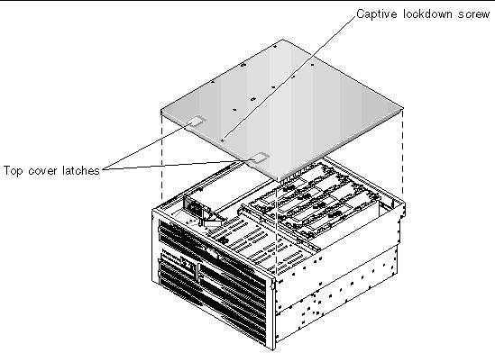
4. Loosen the Phillips No. 2 captive lockdown screw securing the top cover to the chassis.
The lockdown screw is located on the chassis face above the hard drives, between the two latches (FIGURE 2-3).

5. Pull the latches up to release the top cover from the chassis, then lift the cover up and off the chassis (FIGURE 2-3).
1. Insert the back edge of the top cover under the lip on the back panel.
2. Grasp the latches and lower the top cover onto the chassis (FIGURE 2-3).
3. Release the latches when the top cover is seated on the chassis.
4. Tighten the Phillips No. 2 captive lockdown screw that secures the top cover to the chassis.
The lockdown screw is located on the chassis face above the hard drives.
6. Install the system back into the rack.
The procedures for installing the system back into the rack will vary, depending on the type of rack mount kit that you are using. Refer to the Netra 440 Server Installation Guide (817-3882-xx) for more information.
Use the following procedure to prevent static damage whenever you are accessing any of the internal components of the system.
You must have the following items:
2. Remove the system from the rack.
The procedures for removing the system from the rack will vary, depending on the type of rack mount kit that you are using. Refer to the Netra 440 Server Installation Guide (817-3882-xx) for more information.
3. If you are servicing any internal components, remove the top cover.
See Accessing Internal Components.
4. Disconnect the AC or DC power cables.
5. Use an antistatic mat or similar surface.
When performing any installation or service procedure, place static-sensitive parts, such as boards, cards, and hard drives, on an antistatic surface. The following items can be used as an antistatic surface:
6. Use an antistatic wrist strap.
Attach the appropriate end of the strap to the system chassis sheet metal and attach the other end of the strap to your wrist. Refer to the instructions that come with the strap.
|
Note - Ensure that the wrist strap is in direct contact with the metal on the chassis. |
7. Detach both ends of the strap after you have completed the installation or service procedure.
Copyright © 2006, Sun Microsystems, Inc. All Rights Reserved.