| Netra CT Server Installation Guide
|
   
|
This chapter describes how to prepare your site for installing a Netra CT server. This chapter contains the following topics:
Tools Required
Obtain the following tools to perform the procedures in this document:
- No. 1 Phillips screwdriver
- No. 2 Phillips screwdriver
Planning the Placement of the Rack
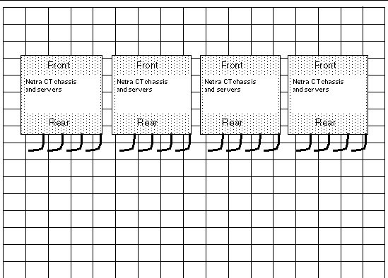
The Netra CT server is designed so that all cables to the CompactPCI boards are connected from the rear of the chassis. The servers are used in areas where the rack is positioned in a room in such a way that both the front and the rear of the chassis are accessible.
FIGURE 2-1 shows an example of a server room layout and how servers might be positioned.
FIGURE 2-1 Example of a Server Room Layout
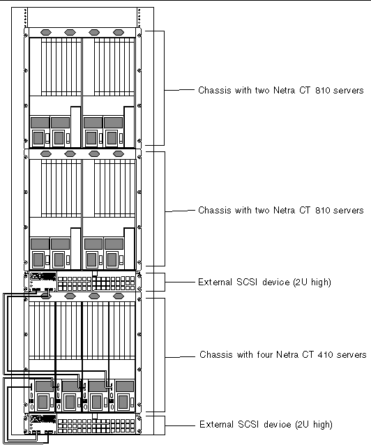
Planning the Rackmounting Configuration
You can mount several Netra CT chassis into a rack, depending on the size and model of the rack. For example, you could install up to three Netra CT chassis in a standard 19-inch rack, with room left over for one or more external SCSI devices.
The following figures show how the Netra CT chassis can be installed in a rack with supported external SCSI devices. Note that the external SCSI device shown in the figures might be different from the one that you install in your configuration.
FIGURE 2-2 Example Configuration 1: Three Chassis, No External SCSI Devices
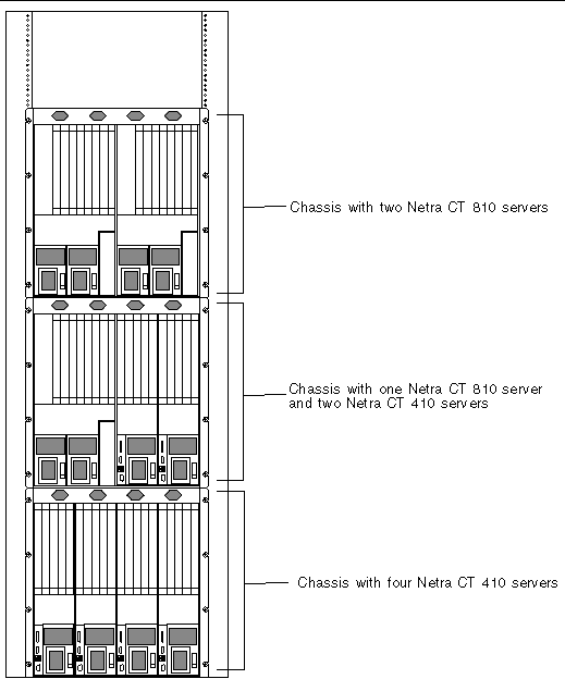
FIGURE 2-3 Example Configuration 2: Three Chassis, Two External SCSI Devices
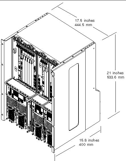
Chassis and Server Physical SpecificationsChassis Physical Specifications
TABLE 2-1 Netra CT Server Chassis Physical Specifications
|
|
U.S.
|
Metric
|
|
Width
|
17.5 inches
|
444.5 mm
|
|
Depth:
|
|
|
- Default configuration, with rackmount brackets extended as shown in FIGURE 2-4
|
15.8 inches
|
400 mm
|
- With rackmount brackets flush against the bottom of the chassis
|
13.8 inches
|
350 mm
|
|
Height
|
21 inches
|
533.6 mm
|
|
Weight (empty)
|
74 lb
|
33.6 kg
|
|
Weight (fully loaded)
|
150 lb
|
68 kg
|
FIGURE 2-4 Physical Specifications for the Netra CT Chassis
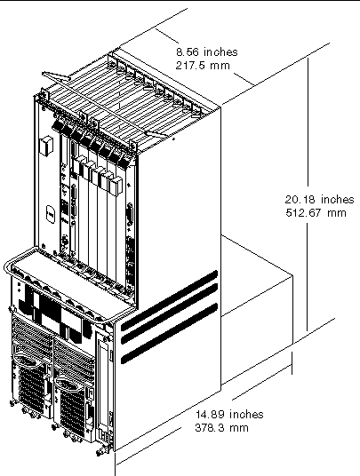
Netra CT 810 Server Physical Specifications
TABLE 2-2 Netra CT 810 Server Physical Specifications
|
Measure
|
U.S.
|
Metric
|
|
Width
|
8.6 inches
|
217.5 mm
|
|
Depth
|
15 inches
|
378.3 mm
|
|
Height
|
20.2 inches
|
512.7 mm
|
|
Weight, fully loaded
|
38 lb
|
17.2 kg
|
FIGURE 2-5 Netra CT 810 Server Physical Specifications
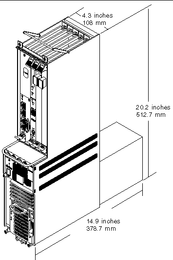
Netra CT 410 Server Physical Specifications
TABLE 2-3 Physical Specifications, Netra CT 410 Server
|
Measure
|
English
|
Metric
|
|
Width
|
4.3 inches
|
108 mm
|
|
Depth
|
14.9 inches
|
378.7 mm
|
|
Height
|
20.2 inches
|
512.7 mm
|
|
Weight, fully loaded
|
22 lb
|
10 kg
|
FIGURE 2-6 Netra CT 410 Server Physical Specifications
Power Source Requirements
This section provides the power source requirements for your servers.
TABLE 2-4 Power Requirements
|
Electrical Element
|
Requirement
|
|
Voltage (nominal)
|
-48 VDC, -60 VDC
|
|
Input current (maximum)
|
14 A
|
|
Max. input surge current
|
17 A
|
The following are requirements and restrictions apply:
- Must be reliably connected to protected earth ground (the battery positive terminal is connected to earth ground)
- Can be supplied by one or two power sources, isolated from each other
- Must be capable of providing up to 600 watts of continuous power per feed
- Is limited to TNV-2, as defined by UL 1950 and IEC 60950
|
Note - The Netra CT server must be installed in a restricted-access location. Per the intent of the National Electrical Code, a restricted-access location is an area intended for qualified or trained personnel only that has access controlled by a locking mechanism, such as a key lock or an access-card system.
|
Supply and Ground Conductor Requirements
The following describes the supply and ground conductor requirements.
- Suitable conductor material: use copper conductors only
- Power supply connections through the input connector: 12 AWG (between the Netra CT server and the source). Three conductors:
- -48V (negative terminal)
- Chassis ground connection
- -48V Return (positive terminal)
- System ground conductor: 12 AWG (to be connected to the chassis)
- Cable insulation rating: minimum of 75°C (167°F), low smoke fume (LSF), flame retardant
- Cable type to be one of the following:
- UL style 1028 or other UL 1581(VW-1) compliant equivalent
- IEEE 383 compliant
- IEEE 1202-1991 compliant
- Branch circuit cable insulation color: per applicable National Electrical Codes
- Grounding cable insulation color: green/yellow
Overcurrent Protection Requirements
The following are the overcurrent protection requirements.
- Overcurrent protection devices must be provided as part of each equipment rack.
- Circuit breakers must be located between the power source and the Netra CT server. Use one 20-amp, double-pole, fast trip DC-rated circuit breaker for each power supply unit.
|
Note - Overcurrent protection devices must meet applicable national and local electrical safety codes and be approved for the intended application.
|

|
Caution - External filtering and surge suppression devices might be required on the power feeds where branch circuit electromagnetic characteristics are unknown.
|
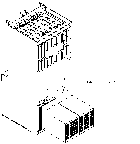
Connecting Logic Ground and Chassis Ground
The Netra CT servers are shipped out of the factory with the logic ground and chassis ground isolated by default. If you want to connect the logic ground and the chassis ground, perform the following steps.
 To Connect Logic and Chassis Ground To Connect Logic and Chassis Ground
|
1. Remove the Netra CT server from the chassis, if you have not done so already.
See To Remove Servers From the Chassis for instructions.
2. Go to the rear of the Netra CT server and locate the two M5 threaded studs on the midplane next to the ground symbols.
3. Remove the two screws and install a grounding plate to connect the two studs (FIGURE 2-7).
This connects the logic ground and chassis ground.
FIGURE 2-7 Installing a Grounding Plate
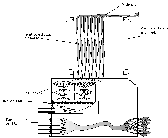
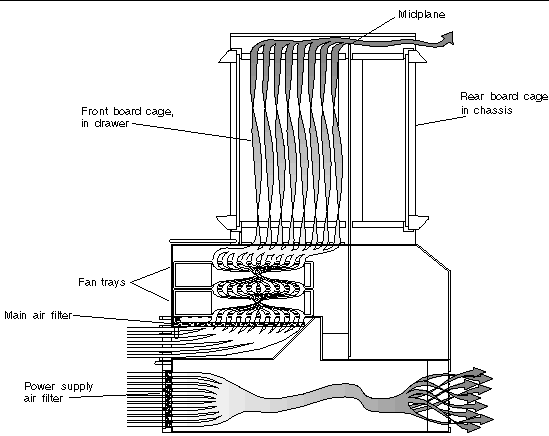
Cooling Requirements
The Netra CT server is cooled by having air drawn in from the front of the system and exhausted out the rear. You must allow 8 inches (203.2 mm) in front and at the rear of the server to ensure proper cooling. FIGURE 2-8 shows the airflow for the Netra CT 810 server, and FIGURE 2-9 shows the airflow for the Netra CT 410 server.
Both the Netra CT 810 servers and the Netra CT 410 servers have two fan trays. The fan tray for the Netra CT 810 server has a single large fan in each tray, while the fan tray for the Netra CT 410 server has two smaller fans. The fan tray is designed to be hot-swappable. High-speed fans are required to support Netra CP2500 boards.
FIGURE 2-8 Airflow, Netra CT 410 Server (Side View)
 [ D ]
[ D ]
FIGURE 2-9 Airflow, Netra CT 810 Server (Side View)
 [ D ]
[ D ]
Environmental Specifications
TABLE 2-5 Environmental Specifications
|
Type
|
Location
|
Minimum to Maximum Range
|
|
Temperature
|
Operating
|
-5°C to 45°C (23°F to 113°F)
|
|
|
Nonoperating
|
-40°C to 70°C (-38°F to 158°F)
|
|
Short term (less than 96 consecutive hrs)
|
Operating
|
-5°C to 55°C (23°F to 131°F)
|
|
Relative humidity
(noncondensing)
|
Operating
|
5% to 93% RH
|
|
|
Nonoperating
|
93% RH max
|
|
Altitude
|
Operating
|
0 ft to 13,123 ft (0 m to 4000 m)
|
|
|
Nonoperating
|
0 ft to 39,370 ft (0 m to 12,000 m)
|
|
Declared noise emissions in accordance with ISO 9296
|
|
Chassis w/two Netra CT 810 servers
|
|
Sound power LWAd Operating 6.7 B
(1B = 10 dB)
|
|
|
|
Idle 6.7 B
|
|
Chassis w/four Netra CT 410 servers
|
|
Sound power LWAd Operating 7.1 B
(1B = 10 dB)
|
|
|
|
Idle 7.1 B
|
| Netra CT Server Installation Guide
|
819-2740-10
|
|
Copyright © 2007, Sun Microsystems, Inc. All Rights Reserved.