| Sun Fire X4150 Server Service Manual |
| C H A P T E R 4 |
|
Servicing Motherboard Components |
This chapter describes how to replace the motherboard and its components in the Sun Fire X4150 Server.
| Note - Before performing any of the procedures in this chapter, perform the procedures described in Chapter 2, Preparing to Service the System. |
The following topics are covered in this chapter:
| Note - Never attempt to run the server with the covers removed. Hazardous voltage present. |


|
Caution - Equipment damage possible. The covers must be in place for proper air flow. |
This section describes how to diagnose and replace faulty FB-DIMMs (fully buffered DIMMs). The following topics are covered:
| Note - This is a customer-replaceable unit. |

|
Caution - This procedure requires that you handle components that are sensitive to static discharge. This sensitivity can cause the component to fail. To avoid damage, ensure that you follow antistatic practices as described in Section 2.7, Performing Electrostatic Discharge and Antistatic Prevention Measures. |
|
The Sun Fire X4150 Server Service Required LED is lit if the system detects a FB-DIMM fault.
To use the rear panel Locator button to identify faulty FB-DIMMs:
1. Unplug all power cords from the rear panel.
2. Press the remind button (FIGURE 4-1).

3. Note the location of faulty FB-DIMMs.
Faulty FB-DIMMs are identified with a corresponding amber LED on the motherboard.
4. Ensure that all FB-DIMMs are seated correctly in their slots. If re-seating the FB-DIMM does not fix the problem, remove and replace the faulty FB-DIMM.
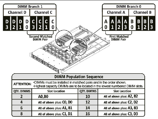
Use the FB-DIMM guidelines, FIGURE 4-2, FIGURE 4-3, and TABLE 4-1 to help you plan the memory configuration of your server.
Any even number of DIMM's is allowed. The DIMMs must be populated in matched pairs. The pairs must be identical in organization, size and speed. See TABLE 4-1 for detailed configuration information.
| Note - FB-DIMM names in ILOM messages are displayed with the full name, such as /SYS/Memory/DIMM_D0. |
FIGURE 4-3 Memory Organization

|
|
|
Caution - Ensure that all power is removed from the server before removing or installing FB-DIMMs. You must disconnect the power cables before performing this procedure. |
1. Review Section 4.1.1, FB-DIMM Guidelines for memory configuration information.
2. Prepare the server for service.
See Section 2.4, Powering Off the Server.
b. Disconnect the power cord (or cords) from the power supply (or supplies).
See Section 2.4, Powering Off the Server.
c. Extend the server into the maintenance position.
See Section 2.5, Extending the Server to the Maintenance Position.
d. Attach an antistatic wrist strap.
See Section 2.7, Performing Electrostatic Discharge and Antistatic Prevention Measures.
See Section 2.8, Removing the Top Cover.
3. If you are replacing a faulty FB-DIMM, press the “Remind” button to activate the FB-DIMM status LEDs after power is removed.
All faulty FB-DIMMs are indicated with an amber LED on the motherboard, so that you can install the replacement FB-DIMM in the same location.
| Tip - Make a note of the faulty FB-DIMM location. |
4. Push down on the ejector tabs on each side of the FB-DIMM until the FB-DIMM is released (FIGURE 4-4).
5. Grasp the top corners of the faulty FB-DIMM and remove it from the server.

6. Place the FB-DIMM on an antistatic mat.
7. Repeat Step 4 through Step 6 to remove any additional FB-DIMMs.
|
| Tip - See Section 4.1.1, FB-DIMM Guidelines for information about configuring the FB-DIMMs. |
1. Unpackage the replacement FB-DIMMs and place them on an antistatic mat.
2. Ensure that the ejector tabs are in the open position.
3. Line up the replacement FB-DIMM with the connector (FIGURE 4-5).
Align the FB-DIMM notch with the key in the connector. This ensures that the FB-DIMM is oriented correctly.
4. Push the FB-DIMM into the connector until the ejector tabs lock the FB-DIMM in place.
If the FB-DIMM does not easily seat into the connector, verify that the orientation of the FB-DIMM is as shown in FIGURE 4-5. If the orientation is reversed, damage to the FB-DIMM might occur.
5. Repeat Step 2 through Step 4 until all replacement FB-DIMMs are installed.
See Section 6.1, Installing the Top Cover.
7. Slide the server into the rack.
See Section 6.3, Returning the Server to the Normal Rack Position.
8. Reconnect the power cord (or cords) to the power supply (or supplies).
Verify that the AC Present LED is lit.
See Section 6.4, Powering On the Server.
See Section 6.4, Powering On the Server.
FIGURE 4-5 Installing FB-DIMMs

|
Before you begin, see Section 4.1.1, FB-DIMM Guidelines, for information about FB-DIMM configuration guidelines.
1. Unpackage the replacement FB-DIMMs and place them on an antistatic mat.
2. Ensure that the ejector tabs are in the open position.
3. Line up the FB-DIMM with the connector (FIGURE 4-5).
Align the FB-DIMM notch with the key in the connector. This ensures that the FB-DIMM is oriented correctly.
4. Push the FB-DIMM into the connector until the ejector tabs lock the FB-DIMM in place.
If the FB-DIMM does not easily seat into the connector, verify that the orientation of the FB-DIMM is as shown in FIGURE 4-5. If the orientation is reversed, damage to the FB-DIMM might occur.
5. Repeat Step 2 through Step 4 until all FB-DIMMs are installed.
6. Return the server to operation.
See Section 6.1, Installing the Top Cover.
b. Slide the server into the rack.
See Section 6.3, Returning the Server to the Normal Rack Position.
c. Reconnect the power cord (or cords) to the power supply (or supplies).
Verify that the AC Present LED is lit.
See Section 6.4, Powering On the Server.
See Section 6.4, Powering On the Server.
You must remove the air baffle when removing and installing the motherboard.
| Note - This is a customer-replaceable unit. |
|
|
Caution - To prevent the system from overheating, ensure that the air baffle is correctly installed before powering on the server. |
|
1. Prepare the server for service.
See Section 2.4, Powering Off the Server.
b. Disconnect the power cord (or cords) from the power supply (or supplies).
See Section 2.4, Powering Off the Server.
c. Slide the server out of the rack.
See Section 2.5, Extending the Server to the Maintenance Position.
d. Attach an antistatic wrist strap.
See Section 2.7, Performing Electrostatic Discharge and Antistatic Prevention Measures.
See Section 2.8, Removing the Top Cover.
Slide the duct off of the screws and remove the air baffle as shown in FIGURE 4-6.
FIGURE 4-6 Removing the Air Baffle
.")
|
|
|
Caution - When the server is in operation, ensure that the air baffle is correctly installed to prevent the system from overheating. |
1. Install the air baffle into the chassis as shown in FIGURE 4-7.
Ensure that the air baffle is aligned and fully seated in the chassis.
2. Return the server to operation.
See Section 6.1, Installing the Top Cover.
b. Slide the server into the rack.
See Section 6.3, Returning the Server to the Normal Rack Position.
c. Reconnect the power cord (or cords) to the power supply (or supplies).
Verify that the AC Present LED is lit.
See Section 6.4, Powering On the Server.
See Section 6.4, Powering On the Server.
FIGURE 4-7 Installing the Air Baffle

PCIe cards are installed on vertical risers. You must remove the relevant riser to access a PCIe card. You must remove all three PCIe risers when replacing the motherboard.
| Note - This is a customer-replaceable unit. |
|
|
Caution - This procedure requires that you handle components that are sensitive to static discharge. This sensitivity can cause the component to fail. To avoid damage, ensure that you follow antistatic practices as described in Section 2.7, Performing Electrostatic Discharge and Antistatic Prevention Measures. |
|
|
|
Caution - Ensure that all power is removed from the server before removing or installing risers. You must disconnect the power cables before performing this procedure. |
1. Prepare the server for service.
See Section 2.4, Powering Off the Server.
b. Disconnect the power cord (or cords) from the power supply (or supplies).
See Section 2.4, Powering Off the Server.
c. Attach an antistatic wrist strap.
See Section 2.7, Performing Electrostatic Discharge and Antistatic Prevention Measures.
2. Disconnect any data cables connected to the cards on the PCIe riser being removed.
Label the cables to ensure proper connection later.
3. Slide the server out of the rack.
See Section 2.5, Extending the Server to the Maintenance Position.
4. If you are servicing a PCIe card, locate its position in the system.
5. Remove the back panel crossbar.
a. Loosen the captive Phillips screw on each end of the back panel crossbar.
b. Lift the crossbar up and back to remove it from the chassis. (FIGURE 4-8)
c. Remove the riser and any PCIe cards attached to it as a unit.
FIGURE 4-8 Removing the Crossbar

6. Lift the riser up to remove it from the system (FIGURE 4-9).
a. Loosen the captive Phillips screw on the end of the riser.
b. Remove the riser and any PCIe cards attached to it as a unit.
FIGURE 4-9 Removing a PCIe Riser

|
The following tools are needed for this procedure:
|
|
Caution - Ensure that all power is removed from the server before removing or installing risers. You must disconnect the power cables before performing this procedure. |
1. Lower the PCIe riser and any cards attached to it into the system.
2. Slide the back of the riser into the motherboard back panel stiffener.
3. Install the screw that secures the riser to the motherboard (FIGURE 4-10).
4. Install the back panel crossbar.
Slide the crossbeam down over the PCIe risers. The crossbar is secured with two captive Phillips screws.
5. Slide the server into the rack. See Section 6.3, Returning the Server to the Normal Rack Position.
6. Connect any data cables you removed to service the PCIe cards.
7. Reconnect the power cord (or cords) to the power supply (or supplies).
Verify that the AC Present LED is lit.
See Section 6.4, Powering On the Server.
FIGURE 4-10 Installing a PCIe riser

See Section 4.4.1, Sun Fire X4150 Server PCIe Card Guidelines for PCIe card configuration guidelines.
| Note - This is a customer-replaceable unit. |
|
|
Caution - This procedure requires that you handle components that are sensitive to static discharge. This sensitivity can cause the component to fail. To avoid damage, ensure that you follow antistatic practices as described in Section 2.7, Performing Electrostatic Discharge and Antistatic Prevention Measures. |
|
|
Caution - Ensure that all power is removed from the server before removing or installing expansion cards. You must disconnect the power cables before performing this procedure. |
The PCI expansion system is configured using a variety of riser cards. The connector is an x16 mechanically but electrically an x8. Only low profile half length cards are supported.
|
|
|
Caution - Ensure that all power is removed from the server before removing or installing expansion cards. You must disconnect the power cables before performing this procedure. |
1. Locate the PCIe card that you want to remove, and note its corresponding riser board.
See Section 1.4, Sun Fire X4150 Server Rear Panel Features for more information about PCIe slots and their locations.
2. If necessary, make a note of where the PCIe cards are installed.
3. Unplug all data cables from the card.
Note the location of all cables for reinstallation later.
4. Remove the riser board (FIGURE 4-11).
See Section 4.3, Servicing PCIe Risers.
5. Carefully remove the PCIe card from the riser board connector.
6. Place the PCIe card on an antistatic mat.
7. If you are not replacing the PCIe card, install a PCIe filler panel.
PCIe filler panels are located in the motherboard back panel.
FIGURE 4-11 Removing a PCIe Card

|
1. Unpackage the replacement PCIe card and place it on an antistatic mat.
2. Locate the proper PCIe slot for the card you are replacing.
3. If necessary, review the PCIe Card Guidelines to plan your installation.
See Section 4.4.1, Sun Fire X4150 Server PCIe Card Guidelines for additional information.
4. Remove the PCIe riser board.
See Section 4.3, Servicing PCIe Risers.
5. Remove the PCI filler panel.
PCIe filler panels are located in the motherboard back panel.
6. Insert the PCIe card into the correct slot on the riser board (FIGURE 4-12).
a. Slide the riser back until it seats in its slot in the back panel.
b. Tighten the captive No. 2 Phillips screw securing the riser to the motherboard.
8. Return the server to operation.
See Section 6.1, Installing the Top Cover.
b. Slide the server into the rack.
See Section 6.3, Returning the Server to the Normal Rack Position.
c. Connect any data cables required to the PCIe card.
Route data cables through the cable management arm.
d. Reconnect the power cord (or cords) to the power supply (or supplies).
Verify that the AC Present LED is lit.
See Section 6.4, Powering On the Server.
See Section 6.4, Powering On the Server.
FIGURE 4-12 Installing a PCIe Card

The battery maintains system time when the server is powered off and a time server is unavailable. If the server fails to maintain the proper time when powered off and not connected to a network, replace the battery.
You need a small (No. 1 flat-blade) screwdriver.
| Note - This is a customer-replaceable unit. |
|
|
Caution - Ensure that all power is removed from the server before removing or installing the battery. You must disconnect the power cables from the system before performing this procedure. |

|
See Section 4.4.1, Sun Fire X4150 Server PCIe Card Guidelines.
2. Using a small (No. 1 flat-blade) screwdriver, press the latch and remove the battery from the motherboard.
|
1. Unpackage the replacement battery.
2. Press the new battery into the motherboard.
Install the positive side (+) facing upward, away from the motherboard.
See Section t, To Install a PCIe Riser.
4. Use the ILOM set date command to set the day and time.
You must remove the motherboard assembly to access the following components:
| Note - FRU: This field-replaceable unit should be replaced only by qualified service technicians. Contact your Sun Service representative for assistance. |
|
|
Caution - This procedure requires that you handle components that are sensitive to electrostatic discharge. This discharge can cause server components to fail. To avoid damage, ensure that you follow the antistatic practices as described in Section 2.7, Performing Electrostatic Discharge and Antistatic Prevention Measures. |
|
|
Caution - This procedure requires removing the server from the rack. The server is heavy. Two people are required to remove it from the rack. |
|
You need a thermal grease kit to replace the processors. You must remove a heat sink to replace the motherboard, to access screws.
1. Prepare the server for service.
See Section 2.4, Powering Off the Server.
b. Disconnect the power cord (or cords) from the power supply (or supplies).
See Section 2.4, Powering Off the Server.
c. Remove the server from the rack.
See Section 2.6, Removing a Server From the Rack.
d. Extend the server into the maintenance position.
See Section 2.5, Extending the Server to the Maintenance Position.
e. Attach an antistatic wrist strap.
See Section 2.7, Performing Electrostatic Discharge and Antistatic Prevention Measures.
See Section 2.8, Removing the Top Cover.
3. Remove the PCIe cards and risers.
See To Remove a PCIe Riser. Make note of the location of expansion cards in the PCIe risers.
4. Disconnect the power distribution board ribbon cable.
5. If you are replacing the motherboard, remove the FB-DIMMs.
Make note of the memory configuration so that you can install the FB-DIMMs in the replacement motherboard.
6. Disconnect the drive data cables.
|
|
Caution - The drive data cables are delicate. Ensure they are safely out of the way when servicing the motherboard. |
7. Remove the plastic air flow baffle from between the fans and the motherboard.
8. Remove the processor heat sinks from the motherboard assembly.
9. Remove the 4 screws that secure the motherboard to the bus bar.
Use a No. 2 Phillips screwdriver.
10. Loosen the green captive screw on the front of the motherboard, that secures the motherboard tray to the chassis.
11. If you are replacing the motherboard only, remove the processors, as required.
12. Lift the motherboard assembly out of the chassis (FIGURE 4-14).
Move the motherboard carefully.
13. Place the motherboard assembly on an antistatic mat.
FIGURE 4-14 Removing the Motherboard Assembly

|
|
Caution - This procedure requires that you handle components that are sensitive to static discharge. Static discharges can cause the component failures. To avoid damage, ensure that you follow antistatic practices as described in Section 2.7, Performing Electrostatic Discharge and Antistatic Prevention Measures. |
See Section 2.4, Powering Off the Server.
2. Attach an antistatic wrist strap.
See Section 2.7, Performing Electrostatic Discharge and Antistatic Prevention Measures.
3. Place the motherboard into the chassis (FIGURE 4-15).
Position the motherboard carefully.
4. Install the 4 screws that secure the motherboard to the bus bar.
Use a No. 2 Phillips screwdriver.
5. Tighten the green captive screw on the front of the motherboard, that secures the motherboard tray to the chassis.
6. If you are replacing the motherboard only, replace the processors, as required.
Apply thermal grease. Follow the applicable grease procedure included with the grease.
7. Install the plastic air flow baffle between the fans and the motherboard.
8. Install the processor heat sinks. See To Install a Processor FRU.
9. Carefully connect the power distribution board ribbon cable to the motherboard.
Make sure it is seated properly.
10. Connect the two drive data cables.
|
|
Caution - The drive data cables are delicate. Carefully connect them and make sure that they are seated properly when servicing the motherboard. |
11. Install all FB-DIMMs in the motherboard assembly.
| Note - Only install the FB-DIMMs in the slots (connectors) from which they were removed. See Section 4.1.1, FB-DIMM Guidelines. |
See To Install the Air Baffle.
13. Reinstall the PCIe cards and risers.
14. Return the server to operation.
See Section 6.1, Installing the Top Cover.
b. Install the server into the rack.
See Section 6.2, Reinstalling the Server in the Rack.
c. Reconnect the power cord (or cords) to the power supply (or supplies).
Verify that the AC Present LED is lit.
See Section 6.4, Powering On the Server.
See Section 6.4, Powering On the Server.
FIGURE 4-15 Installing the Motherboard Assembly

The following topics are covered:
See Section 1.5, Illustrated Parts Breakdown for illustrations of the server and processors.
| Note - FRU: This field-replaceable unit should be replaced only by qualified service technicians. Contact your Sun Service representative for assistance. |
|
The following LEDs are lit when a processor fault is detected:
FIGURE 4-16 Detecting Processor Failure

1. Prepare the server for service.
See Section 2.4, Powering Off the Server.
b. Disconnect the power cord (or cords) from the power supply (or supplies).
See Section 2.4, Powering Off the Server.
c. Slide the server out of the rack.
See Section 2.5, Extending the Server to the Maintenance Position.
d. Attach an antistatic wrist strap.
See Section 2.7, Performing Electrostatic Discharge and Antistatic Prevention Measures.
See Section 2.8, Removing the Top Cover.
2. Identify which processor to remove (FIGURE 4-17).
CPU 0 is closest to the PSU bay.
3. Unscrew the two heatsink screws.
4. Twist the heatsink slightly to break the seal with grease, and then lift off the heatsink.
5. Disengage the lever by pushing down and moving to the side, and then rotating upward.
FIGURE 4-17 Removing a Processor

|
1. Prepare the server for service.
See Section 2.4, Powering Off the Server.
b. Disconnect the power cord (or cords) from the power supply (or supplies).
See Section 2.4, Powering Off the Server.
c. Slide the server out of the rack.
See Section 2.5, Extending the Server to the Maintenance Position.
d. Attach an antistatic wrist strap.
See Section 2.7, Performing Electrostatic Discharge and Antistatic Prevention Measures.
See Section 2.8, Removing the Top Cover.
2. Remove the heatsink on top of the failed processor.
3. Remove the failed processor.
4. Clean off the old thermal interface material from the heatsink and processor, using the supplied alcohol wipe (FIGURE 4-18).
6. Place the new processor in the socket.
Make sure the orientation is correct.
Make sure the pressure plate sits flat around the periphery of the processor.
8. Engage the lever by rotating downward and slipping under the catch.
9. Using the supplied grease syringe, empty the syringe on to the processor in a star shaped pattern.
10. Smooth the grease into a thin even layer on top of the processor.
You can use a piece of plastic bag over your finger.
11. Orient the heatsink so that the two screws line up with the mounting studs (FIGURE 4-19).
12. Tighten the screws alternately one 1/2 turn until fully seated.
FIGURE 4-18 Installing a Processor (Part 1)
.")
13. Return the server to operation.
See Section 6.1, Installing the Top Cover.
b. Install the server into the rack.
See Section 6.2, Reinstalling the Server in the Rack.
c. Reconnect the power cord (or cords) to the power supply (or supplies).
Verify that the AC Present LED is lit.
See Section 6.4, Powering On the Server.
See Section 6.4, Powering On the Server.
FIGURE 4-19 Installing a Processor (Part 2)
.")
|
To install an XOption processor.
1. Prepare the server for service.
See Section 2.4, Powering Off the Server.
b. Disconnect the power cord (or cords) from the power supply (or supplies).
See Section 2.4, Powering Off the Server.
c. Slide the server out of the rack.
See Section 2.5, Extending the Server to the Maintenance Position.
d. Attach an antistatic wrist strap.
See Section 2.7, Performing Electrostatic Discharge and Antistatic Prevention Measures.
See Section 2.8, Removing the Top Cover.
2. Remove the shipping cover from socket.
3. Clean the top of the processor with the provided alcohol wipe.
4. Place the processor in the socket with the correct orientation.
Make sure the pressure plate sits flat around the periphery of the processor.
6. Engage the lever by rotating downward and slipping under the catch.
7. Remove the plastic protective cover from heatsink.
Be careful not to disturb or touch the pre-installed thermal interface material.
8. Orient the heatsink so the two screws line up with the mounting studs.
9. Tighten the screws alternately one 1/2 turn until fully seated.
10. Return the server to operation.
See Section 6.1, Installing the Top Cover.
b. Install the server into the rack.
See Section 6.2, Reinstalling the Server in the Rack.
c. Reconnect the power cord (or cords) to the power supply (or supplies).
Verify that the AC Present LED is lit.
See Section 6.4, Powering On the Server.
See Section 6.4, Powering On the Server.
The following topics are covered:
Clearing CMOS settings resets the BIOS settings, including the BIOS password. You can reset a password from the BIOS screen or with a jumper. You can also clear the NVRAM or BIOS Password by changing the J23 jumper position as follows.
J23 jumper position 1-3: Clears CMOS NVRAM
J23 jumper position 2-4: Clears the Password
Access the 6-pin J23 jumper on the motherboard, located near the CR-2032 battery, below PCI-E riser 0.
|
To reset a password for the Service Processor, access the BIOS Security screen.
2. Press F2 at the Sun splash screen to enter Setup.
3. At the BIOS screen, move to the Security Screen tab.
|
To reset a password for the BIOS by changing a jumper.
See Section 2.4, Powering Off the Server.
2. Disconnect the power cord (or cords) from the power supply (or supplies).
See Section 2.4, Powering Off the Server.
3. Extend the server into the maintenance position.
See Section 2.5, Extending the Server to the Maintenance Position.
4. Attach an antistatic wrist strap.
See Section 2.7, Performing Electrostatic Discharge and Antistatic Prevention Measures.
See Section 2.8, Removing the Top Cover.
Access the J23 jumper on the rear of the motherboard, opposite of the power supply unit.
7. Place the jumper on position 2-4.
8. Power on the server and boot until you see a message that the Password has been cleared.
9. Power off the server, and remove AC power.
10. Remove the jumper from position 2-4, and replace it back to its original position.
See Section 6.1, Installing the Top Cover.
12. Slide the server into the rack.
See Section 6.3, Returning the Server to the Normal Rack Position.
13. Reconnect the power cord (or cords) to the power supply (or supplies).
Verify that the AC Present LED is lit.
See Section 6.4, Powering On the Server.
See Section 6.4, Powering On the Server.
|
To clear the CMOS NVRAM using a jumper:
See Section 2.4, Powering Off the Server.
2. Disconnect the power cord (or cords) from the power supply (or supplies).
See Section 2.4, Powering Off the Server.
3. Extend the server into the maintenance position.
See Section 2.5, Extending the Server to the Maintenance Position.
4. Attach an antistatic wrist strap.
See Section 2.7, Performing Electrostatic Discharge and Antistatic Prevention Measures.
See Section 2.8, Removing the Top Cover.
The 6-pin jumper is located near the CR-2032 battery, below PCI-E riser 0.
7. Place the jumper on position 1-3.
8. Power on the server and boot until message about NVRAM has been cleared.
9. Power off the server, and remove AC power.
10. Remove jumper from position 1-3, and replace it back in its original location.
See Section 6.1, Installing the Top Cover.
12. Slide the server into the rack.
See Section 6.3, Returning the Server to the Normal Rack Position.
13. Reconnect the power cord (or cords) to the power supply (or supplies).
Verify that the AC Present LED is lit.
See Section 6.4, Powering On the Server.
See Section 6.4, Powering On the Server.
If the SP (service processor) software becomes corrupted, you can reinstall the default SP software image from the Tools and Drivers CD.
1. Copy the following SP files from the Tools and Drivers CD, located in the BMCrecovery directory, to a USB flash device.
2. Remove AC power from the server to be flashed.
See Section 2.4, Powering Off the Server.
|
|
Caution - Do not attempt to flash the system while it is still powered on. An unrecoverable error might occur. |
3. Disconnect the power cord (or cords) from the power supply (or supplies).
See Section 2.4, Powering Off the Server.
4. Extend the server into the maintenance position.
See Section 2.5, Extending the Server to the Maintenance Position.
5. Attach an antistatic wrist strap.
See Section 2.7, Performing Electrostatic Discharge and Antistatic Prevention Measures.
See Section 2.8, Removing the Top Cover.
7. Remove PCI cards from Riser 1.
See Section t, To Remove PCIe Cards.
8. Use a jumper cap to short the pins at jumper J16 on the server motherboard.
JP16 is located toward the rear of the board, between Riser 1 and Riser 2.
9. Insert a bootable flash drive into a USB port.
See Section 6.4, Powering On the Server.
See Section 6.4, Powering On the Server.
A message appears stating that the BMC was not found.
The server takes up to three minutes to boot.
12. Press F2 to enter system BIOS and verify that the Flash device is in the boot order.
13. After the flash device has booted, run the following command:
socflash.exe SP binary backup file
socflash.exe s92v092.bin backup.bin
14. After a successful flash, remove the AC power.
See Section 2.4, Powering Off the Server.
16. Remove the flash drive from the USB port.
17. Replace PCI cards from Riser 1.
See Section 6.1, Installing the Top Cover.
19. Slide the server into the rack.
See Section 6.3, Returning the Server to the Normal Rack Position.
20. Reconnect the power cord (or cords) to the power supply (or supplies).
Verify that the AC Present LED is lit.
See Section 6.4, Powering On the Server.
See Section 6.4, Powering On the Server.
22. Confirm that the SP is listed in the BIOS settings under Server/AST2000 LAN Configuration.
| Sun Fire X4150 Server Service Manual | 820-1852-13 |
Copyright © 2009 Sun Microsystems, Inc. All rights reserved.
 To Identify Faulty FB-DIMMs