| Sun LSI 106x RAID User’s Guide |
| C H A P T E R 5 |
|
Creating Integrated Striping Volumes |
This chapter explains how to create Integrated Striping (IS) volumes using the LSI SAS BIOS Configuration Utility (SAS BIOS CU). The chapter includes these topics:
You can use the SAS BIOS CU to create one or two IS volumes, with up to twelve drives total, on an LSI SAS controller. Each volume can have from two to ten drives. Disks in an IS volume must be connected to the same LSI SAS controller, and the controller must be in the BIOS boot order.
Although you can use disks of different size in IS volumes, the smallest disk determines the “logical” size of each disk in the volume. In other words, the excess space of the larger member disk(s) is not used. Usable disk space for each disk in an IS volume is adjusted down to leave room for metadata. Usable disk space may be further reduced to maximize the ability to interchange disks in the same size classification. The supported stripe size is 64 kilobytes.
Refer to IS Features for more information about Integrated Striping volumes.
The SAS BIOS CU is part of the Fusion-MPT BIOS. When the BIOS loads during boot and you see the message about the LSI Configuration Utility, press Ctrl-C to start it. After you do this, the message changes to:
Please wait, invoking SAS Configuration Utility...
After a brief pause, the main menu of the SAS BIOS CU appears. On some systems, however, the following message appears next:
LSI Logic Configuration Utility will load following initialization!
In this case, the SAS BIOS CU will load after the system has completed its power-on self test.
Follow the steps below to configure an Integrated Striping (IS) volume with the SAS BIOS CU. The procedure assumes that the required controller(s) and disks are already installed in the computer system. You can configure an IM/IME volume and an IS volume on the same SAS controller.
|
1. On the Adapter List screen of the SAS BIOS CU, use the arrow keys to select a SAS adapter.
2. Press Enter to go to the Adapter Properties screen, shown in FIGURE 5-1.
FIGURE 5-1 Adapter Properties Screen
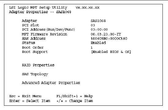
3. On the Adapter Properties screen, use the arrow keys to select RAID Properties and press Enter.
4. When you are prompted to select a volume type, select Create IS Volume.
5. The Create New Array screen shows a list of disks that can be added to a volume.
FIGURE 5-2 shows the Create New Array screen with an IS volume configured with two drives.
FIGURE 5-2 Create New Array Screen

6. Move the cursor to the RAID Disk column. To add a disk to the volume, change the No to Yes by pressing the + key, - key, or space bar. As disks are added, the Array Size field changes to reflect the size of the new volume.
There are several limitations when creating an IS (RAID 0) volume:
4. When you have added the desired number of disks to the array, press C, then select Save Changes, and then Exit This Menu to commit the changes. The configuration utility pauses while the array is being created.
The LSI SAS controllers allow you to configure two IS volumes, or an IS volume and an IM/IME volume. If one volume is already configured, and if there are available disk drives, there are two ways to add a second volume.
|
1. In the configuration utility, select an adapter from the Adapter List, and then select the RAID Properties option.
This will display the current volume.
2. Press C to create a new volume.
3. Continue with Step 4 of Creating IS Volumes to create a second IS volume.
|
1. On the Adapter List screen, use the arrow keys to select an LSI SAS adapter.
2. Press Enter to go to the Adapter Properties screen, shown in FIGURE 5-1.
3. On the Adapter Properties screen, use the arrow keys to select RAID Properties and press Enter.
4. Continue with Step 4 of Creating IS Volumes to create a second IS volume.
This section explains how to perform other configuration and maintenance tasks for IS volumes.
|
1. In the configuration utility, select an adapter from the Adapter List. Select the RAID Properties option.
The properties of the current volume appears.
2. If more than one volume is configured, press Alt+N to view the next array.
3. To manage the current array, press Enter when the Manage Array item is selected.
An array can become inactive if, for example, it is removed from one controller or computer and moved to another one. The “Activate Array” option allows you to reactivate an inactive array that has been added to a system. This option is only available when the selected array is currently inactive.
1. Select Activate Array on the Manage Array screen.
2. Press Y to proceed with the activation, or press N to abandon it.
After a pause, the array will become active.
|

|
Caution - Before deleting an array, be sure to back up all data on the array that you want to keep. |
1. Select Delete Array on the Manage Array screen.
2. Press Y to delete the array, or press N to abandon the deletion.
After a pause, the firmware deletes the array.
| Note - Once a volume has been deleted, it cannot be recovered. The master boot records of all disks are deleted. |
You can use the SAS BIOS CU to locate and identify a specific physical disk drive by flashing the drive’s LED. You can also use the SAS BIOS CU to flash the LEDs of all the disk drives in a RAID volume. There are several ways to do this:
1. When you are creating an IS volume, and a disk drive is set to Yes as part of the volume, the LED on the disk drive is flashing. The LED is turned off when you have finished creating the volume.
2. You can locate individual disk drives from the SAS Topology screen. To do this, move the cursor to the name of the disk in the Device Identifier column and press Enter. The LED on the disk flashes until the next key is pressed.
3. You can locate all the disk drives in a volume by selecting the volume on the SAS Topology screen. The LEDs flash on all disk drives in the volume.
| Note - The LEDs on the disk drives will flash as described above if the firmware is correctly configured and the drives or the disk enclosure supports disk location. |
You can select a boot disk in the SAS Topology screen. This disk is then moved to scan ID 0 on the next boot, and remains at this position. This makes it easier to set BIOS boot device options and to keep the boot device constant during device additions and removals. There can be only one boot disk.
1. In the SAS BIOS CU, select an adapter from the Adapter List.
2. Select the SAS Topology option.
The current topology is displayed. If the selection of a boot device is supported, the bottom of the screen lists the Alt+B option. This is the key for toggling the boot device. If a device is currently configured as the boot device, the Device Info column on the SAS Topology screen will show the word “Boot.”
3. To select a boot disk, move the cursor to the disk and press Alt+B.
4. To remove the boot designator, move the cursor down to the current boot disk and press Alt+B. This controller will no longer have a disk designated as boot.
5. To change the boot disk, move the cursor to the new boot disk and press Alt+B. The boot designator will move to this disk.
| Note - The firmware must be configured correctly in order for the Alt+B feature to work. |
| Sun LSI 106x RAID User’s Guide | 820-4933-15 |
Copyright © 2006, 2007 by LSI Logic Corporation. All rights reserved. © 2009 Sun Microsystems, Inc. All rights reserved.
 To Create IS Volumes