| C H A P T E R 4 |
|
CMM Power Management |
This chapter contains ILOM power management information that is specific to the Sun Blade 6000 and Sun Blade 6048 CMM and ILOM 3.x.
For more information on power management, refer to the Oracle Integrated Lights Out Manager (ILOM) 3.0 Concepts Guide.
This chapter contains the information described in the following table.
|
Learn about ILOM readings for specific Sun Blade 6048 Modular System cases |
The Light Load Efficiency Mode (LLEM) is a new feature of CMM ILOM 3.0.6.11.
This section covers the following sections:
Under the LLEM, the CMM monitors the power being used and automatically shuts down the power supply unit (PSU) sides to achieve higher efficiency. While enabled, LLEM runs in both redundant and non-redundant mode.
The CMM always disables PSU sides in descending order. When the power load level increases, the CMM renewably those disabled sides to cover the demand. If a new blade is inserted into the chassis, it can be powered on even if its power budget exceeds the power available from the sides currently turned on.
When an unexpected AC fault occurs, LLEM is suspended and all sides will become enabled, verified by the sensor value of I_V12 and V_OUT_OK. If the fault is cleared, configured LLEM policy automatically goes back into effect.
When the LLEM is disabled, all PSU sides, including those previously disabled, become enabled. This can be verified by the sensor value of I_V12 and V_OUT_OK.
For further information on ILOM power management features, see the Oracle Integrated Lights Out Manager (ILOM) 3.0 Concepts Guide.
This section covers the following procedures:
1. Log in to the ILOM web interface.
2. Click on CMM in the Chassis navigation pane.
3. Navigate to the Configuration --> Policy page.

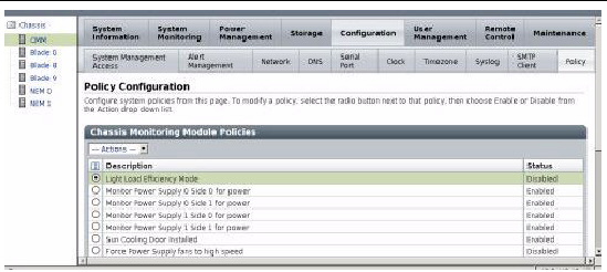
4. Select Light Load Efficiency Mode.
5. Select Enable or Disable from the Actions drop-down list.
6. To turn power supplies on or off in the Policy page:
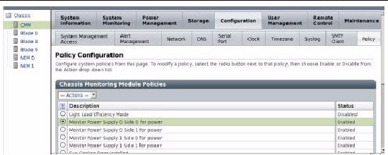
a. Select Monitor Power Supply x Side y for power.
In the following example, Monitor Power Supply 0 Side 0 is selected.

b. Select Enable or Disable from the Actions menu.
1. Log in to the ILOM web interface.
2. Click on CMM in the Chassis navigation pane.
3. Navigate to the Power Management --> Redundancy page.

4. Select one of the following from the drop-down menu:
This section covers the following procedures:
1. Log in to the CMM ILOM CLI.
2. To enable or disable LLEM, use the command:
-> set /CMM/policy LIGHT_LOAD_EFFICIENCY_MODE=[enabled|disabled]
3. When LLEM is disabled, you can turn the PSU sides on or off with this command:
-> set /CMM/policy MONITOR_PSn_SIDEn=[enabled|disabled]
| Note - It is advisable to disable any PSU side first before unplugging the power cord. |
You can check the sensor value of /CH/PSn/Sn/I_12V or /CH/PSn/Sn/V_OUT_OK, where the value of I_12V being 0 or V_OUT_OK deasserted indicates the corresponding side is disabled.
You can disable any PSU sides monitoring. In both redundant and non-redundant modes, LLEM works on those sides that are under monitoring.
1. Log in to the CMM ILOM CLI.
2. Set redundant mode using this command:
-> set /CMM/powermgmt redundancy=n+n
All MONITOR_PSn_SIDEn are set to enabled, and any attempt to disable any PSU side’s monitoring is not allowed.
1. Log in to the CMM ILOM CLI.
2. Set non-redundant mode using this command:
-> set /CMM/powermgmt redundancy=none
A new feature introduced in ILOM 3.0.6.11 allows the adjustment of power supply fan speed.
The high and low speed settings are defined as follows:
| Note - Only force power supply unit (PSU) fans to low speed if half the PEM slots or fewer are in use. |
This section covers the following topics:
|
1. Log in to the ILOM web interface.
2. Click on CMM in the Chassis navigation pane.
3. Navigate to the Configuration --> Policy.

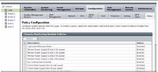
4. Choose one of the following options:
5. Select Enable or Disable from the Actions drop-down menu.
As the power supply fans cool the power supplies, the power supply fans also cool the PEM slots.
| Note - If you enable both fan speed policies, high speed policy dominates. |
|
1. Log in to the ILOM CLI interface.
2. Execute the following command:
-> set /CMM/policy PS_FANS_HIGH=[enabled|disabled]
-> set /CMM/policy PS_FANS_LOW=[enabled|disabled]
As the power supply fans cool the power supplies, the power supply fans also cool the PEM slots.
| Note - If you enable both fan speed policies, high speed policy dominates. |
A new power management option has been added to CMM ILOM 3.0.6.11c (Software Version 3.1.13), which enables the user to disable power management so that blades in the chassis attempt to power on even if power allocation has been exceeded.

|
Caution - Chassis shutdown can occur. Do not disable power management unless you are advised to by Oracle Services personnel. |
To disable power management, when instructed by Oracle Services, use one of the following procedures:
|
1. Log in to the ILOM web interface.
2. Select CMM from the Chassis navigation pane.
3. Navigate to the Configuration --> Policy.
4. Select Manage Chassis Power.
5. Select Disable from the Actions drop-down list.
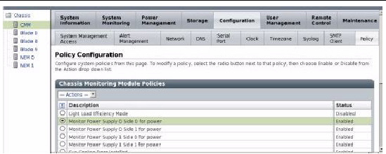
The following ILOM screen graphic shows the Manage Chassis Power option at the bottom of the Policy Configuration page.

|
1. Log in to the CMM ILOM CLI.
2. Type the following command:
-> set /CMM/policy POWER_MANAGEMENT=disabled
The power supply configurations covered in this section apply only to the Sun Blade 6048 Modular System.
This section covers the following topics:
This section specifies how CMM and server module firmware behave when only two of the three power plugs are connected to an A231 power supply unit (PSU).
There are three plugs on the back of each A231 PSU. These plugs are named AC0, AC1, and AC2. Each plug allows connection of a 220V power cord. When only two of the available three plugs are connected to the A231 PSUs, this provides 5600 watts to the entire chassis.
If you connect only two of the total three plugs, connect them to AC0 and AC1. AC2 should not be connected.
For further information on Sun Blade 6048 Modular System sensors, refer to the Oracle Integrated Lights Out Manager (ILOM) 3.0 Supplement for Sun Blade 6000 and Sun Blade 6048 Modular Systems (820-7603).
1. To set up a two power cord configuration, disable the power supply side in the CMM ILOM with the following commands:
-> set /CMM/policy MONITOR_PS0_SIDE2=disabled
-> set /CMM/policy MONITOR_PS1_SIDE2=disabled
2. To view the disabled power cord side 2 configuration, type:
This section provides some of the sensor readings for the system event log (SEL) in cases that are specific to the Sun Blade 6048 Modular System.
To view the SEL using IPMItool, use the following command:
ipmitool -H SPIPaddress -U root -P changeme sel list
When an AC cable gets disconnected, the SEL displays the readings as shown in the example for power supply module 0, side 0 in TABLE 4-1.
| Note - The order of the events might not match the real time event exactly, because that is based on how the sensors are being scanned. |
When an AC cable gets disconnected, then plugged back in, the SEL displays the readings as shown for power supply module 0, side 0 in TABLE 4-2.
When the stop /CH command is applied, the SEL displays the readings as shown in the example in TABLE 4-3. This example describes a two power cord configuration.
When the start /CH command is applied, the SEL displays the readings as shown in the example in TABLE 4-4. This example describes a two power cord configuration.
When one PSU is removed, and there is too much power consumption in the chassis to support PSU redundancy, the SEL displays the readings shown in TABLE 4-5.
TABLE 4-6 shows the SEL readings as a PSU is reinserted into the system and the system recognizes that power has been reapplied.
Copyright © 2010, Oracle and/or its affiliates. All rights reserved.