| Sun Fire X4240 Server Service Manual |
| C H A P T E R 5 |
|
Servicing Infrastructure Boards and Components |
This chapter describes how to replace cold-swappable, field-replaceable units (FRUs) in the Sun Fire X4240.
The following topics are covered:

|
Caution - Never attempt to run the server with the covers removed. Hazardous voltage is present. |

|
Caution - Equipment damage is possible. The covers must be in place for proper air flow. |
You must remove both fan power boards to access the paddle card or to access the drives data cables in the Sun Fire X4240.
| Note - FRU: This field-replaceable unit should be replaced only by qualified service technicians. Contact your Sun Service representative for assistance. |
|
|
Caution - Ensure that all power is removed from the server before removing or installing fan power boards. You must disconnect the power cables before performing this procedure. |
1. Prepare the server for service.
b. Disconnect the power cord (or cords) from the power supply (or supplies).
c. Slide the server out of the rack.
See Extending the Server to the Maintenance Position.
| Note - If you are removing the fan power boards to access the Vertical PDB card or drive cage, you must remove the server from the rack. See Removing a Server From the Rack. |
d. Attach an antistatic wrist strap.
See Performing Electrostatic Discharge and Antistatic Prevention Measures.
| Note - If you are replacing a defective fan power board, remove only the fan modules that are necessary to remove the defective fan power board. |
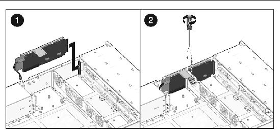
3. Remove the Phillips screw that secures the fan power board to the chassis (FIGURE 5-1).
4. Slide the fan power board to the left to disengage it from the paddle card.
5. Remove the fan power board from the system and place it on an antistatic mat.
FIGURE 5-1 Removing the Fan Power Board

1. Lower the board into its mushroom standoffs in the chassis floor and slide the board to the right into the Paddle card. (FIGURE 5-2)
2. Secure the board to the chassis with a Phillips screw.
FIGURE 5-2 Installing a Fan Power Board

4. Return the server to operation.
b. Slide the server into the rack.
See Returning the Server to the Normal Rack Position.
c. Reconnect the power cord (or cords) to the power supply (or supplies).
Verify that the AC Present LED is lit.
You must remove the drives cage to access the following components:
| Note - FRU: This field-replaceable unit should be replaced only by qualified service technicians. Contact your Sun Service representative for assistance. |
|
|
Caution - Ensure that all power is removed from the server before removing or installing the drives cage. You must disconnect the power cables before performing this procedure. |
1. Prepare the server for service.
b. Disconnect the power cord (or cords) from the power supply (or supplies).
c. Remove the server from the rack.
See Removing a Server From the Rack.
d. Attach an antistatic wrist strap.
See Performing Electrostatic Discharge and Antistatic Prevention Measures.
2. If you are servicing the drives backplane, remove all drives.
See Removing a Hard Drive or SSD.
| Note - Make a note of the drive locations before removing them from the system. You will need to install the drives in the correct locations when reassembling the system. |
3. If you are servicing the drives backplane, remove the DVD/USB module.
See Removing the DVD/USB Module.
5. Remove the fan power boards.
See Removing a Fan Power Board.
6. Remove the No. 2 Phillips screws securing the drives cage to the chassis. (FIGURE 5-3 [1] and [2])
Two screws secure the disk cage to each side of the chassis.
7. Slide the drives cage forward to disengage the backplane from the paddle cards. (FIGURE 5-3 [3])
8. Lift the drives cage up and disconnect the drives data cables. (FIGURE 5-3 [4])
Press the connector release button to release the cable.
9. Set the drive cage on an antistatic mat.
FIGURE 5-3 Removing the Hard Drive Cage

1. Connect the hard drives data cables.
Press the connector into its socket until it snaps into place.
2. Position the hard drive cage in the chassis, over its standoffs. (FIGURE 5-4 [1])
3. Slide the hard drive cage back until the hard drive backplane engages with the paddle card connector. (FIGURE 5-4 [2])
4. Replace the No. 2 Phillips screws securing the hard drive cage to the chassis. (FIGURE 5-4 [3])
Two screws secure the disk cage to each side of the chassis.
5. Install the fan power boards.
See Installing a Fan Power Board.
FIGURE 5-4 Installing the Hard Drive Cage

8. Install the server into the rack.
See Reinstalling the Server in the Rack.
| Note - Ensure you are installing the hard drives in the correct drive bays. |
See Installing a Hard Drive or SSD.
10. Install the DVD/USB module.
See Installing the DVD/USB Module.
11. Return the server to operation.
a. Reconnect the power cord (or cords) to the power supply (or supplies).
Verify that the AC Present LED is lit.
b. Press the power button to power on the server.
You must remove the hard drive backplane to service the front control panel light pipe assemblies.
| Note - FRU: This field-replaceable unit should be replaced only by qualified service technicians. Contact your Sun Service representative for assistance. |
See Removing the DVD/USB Module.
2. Remove the four No. 2 Phillips screws securing the backplane to the hard drive cage. (FIGURE 5-5)
3. Remove the hard drive cage.
4. Slide the backplane down and off the hard drive cage retention hooks.
5. Place the hard drive backplane on an antistatic mat.
FIGURE 5-5 Removing the Hard Drive Backplane

1. Slide the backplane under the retention hooks on the hard drive cage. (FIGURE 5-6)
2. Install the four No. 2 Phillips screws that secure the backplane to the hard drive cage.
The sequence is top left, top right, bottom left, bottom right.
3. Install the hard drive cage.
See Installing the Hard Drive Cage.
See Installing the DVD/USB Module.
FIGURE 5-6 Installing the Hard Drive Backplane

| Note - FRU: This field-replaceable unit should be replaced only by qualified service technicians. Contact your Sun Service representative for assistance. |
1. Remove the hard drive cage.
2. Remove the hard drive backplane.
See Removing the Hard Drive Backplane.
3. Remove the three No. 2 Phillips screws securing the front control panel light pipe assembly to the hard drive cage. (FIGURE 5-7)
4. Slide the light pipe assembly out of the hard drive cage.
FIGURE 5-7 Removing a Light Pipe Assembly

1. Align the light pipe assembly with the mounting holes on the hard drive cage.
2. Secure the light pipe assembly with three No. 2 Phillips screws.
3. Install the hard drive backplane.
See Installing the Hard Drive Backplane.
4. Install the hard drive cage.
See Installing the Hard Drive Cage.
It is easier to service the power distribution board (PDB) with the bus bar assembly attached. If you are replacing a faulty PDB, you must remove the bus bar assembly from the old board and attach it to the new PDB.
You must remove the power distribution board to access the paddle card.
| Note - FRU: This field-replaceable unit should be replaced only by qualified service technicians. Contact your Sun Service representative for assistance. |
1. Remove the motherboard assembly.
See Removing the Motherboard Assembly.
2. Remove all power supplies. (FIGURE 5-8)
a. Grasp the power supply handle and press the release latch.
b. Slide the power supply out of the system.
3. Disconnect the top cover interlock cable from the power distribution board. (FIGURE 5-8)
4. Disconnect the PDB ribbon cable from the Power Supply Unit backplane.
5. Remove the four screws securing the L shaped bus bars from the PSU backplane to the PDB.
6. Remove the No. 2 Phillips screw securing the PDB to the chassis.
7. Grasp the bus bar and pull the PDB/bus bar assembly to the left, away from the paddle card.
8. Lift the PDB/bus bar assembly up and out of the system.
9. Place the PDB/bus bar assembly on an antistatic mat.
FIGURE 5-8 Removing the Power Distribution Board

1. Lower the PDB/bus bar assembly into the chassis. (FIGURE 5-9 [1])
The PDB fits over a series of mushroom standoffs in the floor of the chassis.
2. Slide the PDB/bus bar assembly to the right, until it plugs into paddle card.
3. Install the five No. 2 Phillips screws to secure the PDB to the chassis. [2]
4. Connect the top cover interlock cable to the power distribution board. [3]
5. Connect the PDB ribbon cable to the PSU backplane. [4]
6. Install the power supplies.
Slide each power supply into its bay until it locks into place.
See Installing a Power Supply.
7. Install the motherboard assembly.
See Installing the Motherboard Assembly.
FIGURE 5-9 Installing the Power Distribution Board

In the Sun Fire X4240, the power supply backplane carries 12V power to the power distribution board.
| Note - FRU: This field-replaceable unit should be replaced only by qualified service technicians. Contact your Sun Service representative for assistance. |
1. Remove the motherboard assembly.
See Removing the Motherboard Assembly.
Grasp the power supply handle and press the release latch.
3. Remove the power distribution board.
See Removing the Power Distribution Board.
4. Unscrew the 4 screws that secure the L shaped bus bars to the PSU backplane and the PDB.
5. Remove the No. 2 Phillips screw securing the power supply backplane to the power supply bay. (FIGURE 5-10)
6. Lift the power supply backplane up and off its mushroom standoffs, and out of the system.
7. Place the power supply backplane on an antistatic mat.
FIGURE 5-10 Removing the Power Supply Backplane
.")
1. Mount the power supply backplane to the front of the power supply bay. (FIGURE 5-11)
Place the backplane over its mushroom standoffs and press down toward the floor of the chassis.
FIGURE 5-11 Installing the Power Supply Backplane
 .")
2. Secure the power supply backplane with one No. 2 Phillips screw.
3. Install the power distribution board.
See Installing the Power Distribution Board.
4. Install all power supplies.
Slide each power supply into its bay until it locks into place.
See Installing a Power Supply.
5. Install the motherboard assembly.
See Installing the Motherboard Assembly.
The paddle card assembly includes the top cover interlock switch.
| Note - FRU: This field-replaceable unit should be replaced only by qualified service technicians. Contact your Sun Service representative for assistance. |
1. Remove the motherboard assembly.
See Removing the Motherboard Assembly.
2. Remove the power distribution board.
See Removing the Power Distribution Board.
3. Remove the fan power boards.
See Removing a Fan Power Board.
4. Remove the two No. 2 Phillips screws securing the paddle card to the chassis. (FIGURE 5-12)
5. Slide the paddle card back, away from its connector on the hard drive backplane.
6. Lift the paddle card up and out of the chassis.
7. Place the paddle card on an antistatic mat.
FIGURE 5-12 Removing the Paddle Card

1. Lower the paddle card into the chassis.
The paddle card fits over a series of mushroom standoffs in the chassis side wall.
2. Slide the paddle card forward to plug it into the hard drive backplane. (FIGURE 5-13)
3. Secure the paddle card with two No. 2 Phillips screws.
4. Install the fan power boards.
See Installing a Fan Power Board.
5. Install the power distribution board.
See Installing the Power Distribution Board.
6. Install the motherboard assembly.
See Installing the Motherboard Assembly.
FIGURE 5-13 Installing the Paddle Card
The following topics are covered:
See System Cables for illustrations of cables.
| Note - FRU: This field-replaceable unit should be replaced only by qualified service technicians. Contact your Sun Service representative for assistance. |
To remove drive cables in a SAS configuration.
1. Prepare the server for service.
b. Disconnect the power cord (or cords) from the power supply (or supplies).
c. Slide the server out of the rack.
See Extending the Server to the Maintenance Position.
d. Attach an antistatic wrist strap.
See Performing Electrostatic Discharge and Antistatic Prevention Measures.
4. Remove the fan power boards.
See Removing a Fan Power Board.
5. Untwist the cable tiedowns to release the cables. (FIGURE 5-14)
6. Remove each cable at the drives backplane by pressing the latch and then pulling out the connector.
7. Disconnect each cable at the SAS HBA card by pressing the latch and then pulling out the connector.
8. Pull the cables through the midwall.
Avoid damaging the air blocker.
9. Lift the cables out of the chassis.
FIGURE 5-14 Removing Drive Cables in a SAS Configuration

1. Prepare the server for service.
b. Disconnect the power cord (or cords) from the power supply (or supplies).
c. Slide the server out of the rack.
See Extending the Server to the Maintenance Position.
d. Attach an antistatic wrist strap.
See Performing Electrostatic Discharge and Antistatic Prevention Measures.
4. Remove the fan power boards.
See Removing a Fan Power Board.
5. Thread the power board end of the cables underneath the midwall, towards the drives backplane. (FIGURE 5-15)
a. Connect the connector labeled PB 0, 1, 2, and 3 to the connector furthest from the power supply.
b. Connect the connector labeled PB 4, 5, 6, and 7 to the connector nearest to the power supply.
6. Reinstall the fan boards, making sure the cable is not pinched.
The cable routes through the slot underneath of the fan boards.
See Installing a Fan Power Board.
7. Route the cable towards the power supply bay, and over the notch in the vertical power supply unit backplane.
8. Install the SAS HBA card in PCIe slot 0.
The lower card on the riser is closest to the power supply wall.
9. Install the connector labeled MB 0, 1, 2, and 3 into port 0 of the SAS HBA card, that is closest to the gold fingers.
10. Install the connector labeled MB 4, 5, 6, and 7 into port 0 of the SAS HBA card, that is furthest from the gold fingers.
13. Return the server to operation.
b. Slide the server into the rack.
See Returning the Server to the Normal Rack Position.
c. Reconnect the power cord (or cords) to the power supply (or supplies).
Verify that the AC Present LED is lit.
FIGURE 5-15 Installing Drive Cables in a SAS Configuration

To remove a Power Distribution Board cable.
1. Prepare the server for service.
b. Disconnect the power cord (or cords) from the power supply (or supplies).
c. Slide the server out of the rack.
See Extending the Server to the Maintenance Position.
d. Attach an antistatic wrist strap.
See Performing Electrostatic Discharge and Antistatic Prevention Measures.
3. Remove the PDB end of the cable. (FIGURE 5-16)
a. Release the locking latches on either side and then pull the cable straight up.
b. Grasp each end of the connector on the motherboard, and then pull straight up to disconnect from the connector.
FIGURE 5-16 Removing a PDB Cable

To install a Power Distribution Board cable.
2. Inspect the motherboard pin field to ensure all pins are straight. (FIGURE 5-17)
3. Open the locking latches on the PDB connector.
Ensure the key of the cable lines up with the slot on the connector.
4. Push the cable connector into the PDB connection until it is seated.
The latches should be above the connector housing.
5. Carefully align the motherboard connector to the motherboard pin field.
Gently press the connector down until it is seated. If you feel significant resistance, stop and check the pin alignment.
7. Return the server to operation.
b. Slide the server into the rack.
See Returning the Server to the Normal Rack Position.
c. Reconnect the power cord (or cords) to the power supply (or supplies).
Verify that the AC Present LED is lit.
FIGURE 5-17 Installing a PDB Cable

| Sun Fire X4240 Server Service Manual | 820-3835-14 |
Copyright © 2010, Oracle and/or its affiliates. All rights reserved.