| C H A P T E R 4 |
|
Preparing to Replace Components |
This chapter describes common tasks that must be completed prior to performing a removal or installation procedure on any Sun Ultra 40 Workstation.
The procedures described in this chapter are written for workstation service providers and system administrators.

|
Caution - To prevent equipment damage, review the safety requirements, safety symbols, and safety precautions in this chapter before you perform any replacement procedure. |
This chapter contains the following sections:
This section provides safety precautions to follow when servicing the Sun Ultra 40 Workstation.
For your protection, observe the following safety precautions when setting up your equipment:
http://www.sun.com/documentation/
The following symbols might appear in this book. Please note their meanings:

|
Caution - There is a risk of personal injury and equipment damage. To avoid personal injury and equipment damage, follow the instructions. |

|
Caution - Hot surface. Avoid contact. Surfaces are hot and might cause personal injury if touched. |

|
Caution - Hazardous voltages are present. To reduce the risk of electric shock and danger to personal health, follow the instructions. |
Certain devices, such as such as the motherboard, PCI cards, and hard drives, are sensitive to electrostatic discharge (ESD). They require special handling.
The Sun Ultra 40 Workstation was designed to be serviced with the following tools:
See FIGURE 4-1.
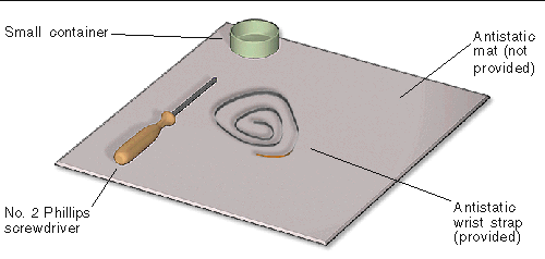
Though not required for component replacement, the following tools have proven helpful in certain situations:
Place ESD-sensitive components such as the motherboard, memory, PCI cards, and hard drives on an antistatic mat. The following items can be used as an antistatic mat:
To prepare the workstation for servicing:
1. Power off the workstation as described in Section 1.4.2, Powering Off the Workstation.
See FIGURE 4-2 for the location of the power button.
2. Power off and disconnect the monitor, keyboard, mouse, network connections, and any peripherals.
3. Disconnect the power cord from the workstation.
See FIGURE 4-3.
4. Press down the two latches on the side cover and lift the cover off the workstation.
See FIGURE 4-4, part 1 for Step 4 through Step 9.
5. Using both hands, place the workstation on its side.
See FIGURE 4-4, part 2.
6. Pivot the workstation support leg underneath the workstation.
See FIGURE 4-4, part 2.
a. Slide the lock block to the front of the system.
b. Press and release the two latches and lift the access panel.
See FIGURE 4-4, part 4.
8. Attach the antistatic wrist strap.
Wrap the adhesive portion around your wrist. Attach the copper end to the rear vent of the chassis. Ensure that the location does not interfere with your service procedure.
See FIGURE 4-4, part 5.
9. If your procedure requires it, lift the fan module up and out.
Grasp it by the handle and slide it straight up.
See FIGURE 4-4, part 5.
10. Find the removal or replacement procedure you need.
See TABLE 4-1.
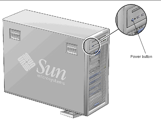
FIGURE 4-2 Power Button Location (Ultra 40 Shown)
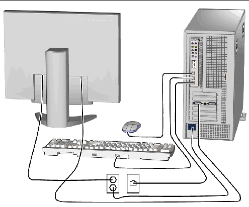
FIGURE 4-3 Disconnecting the Workstation Cables (Ultra 40 Shown)
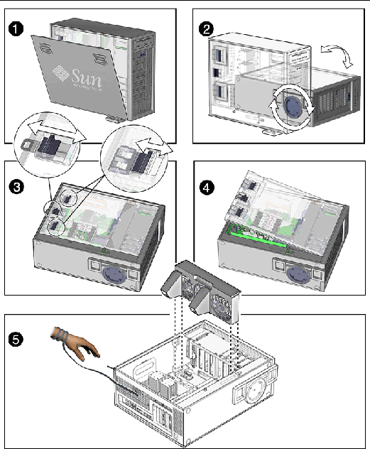
FIGURE 4-4 Removing, Side Cover, Access Panel, and Fan Module (Ultra 40 Shown)
Use the following figures and tables to identify the component that you need to replace and locate the corresponding procedures.
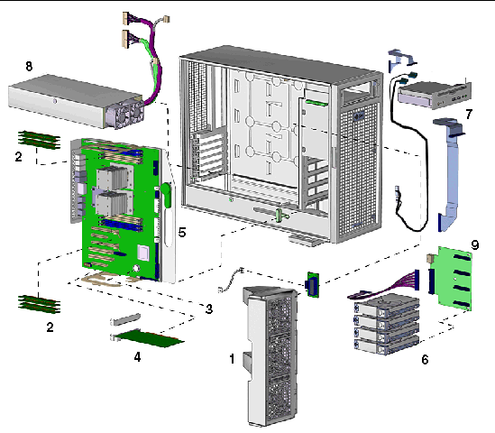
FIGURE 4-5 Ultra 40 Major Workstation Components
|
Section 4.3, Preparing the Workstation for Servicing and
|
||
|
Section 4.3, Preparing the Workstation for Servicing and
|
||
|
Section 6.2, Replacing the Hard Drive Backplane and Signal Cable |
||
|
The following components are not field-replaceable units: side cover and access panel. |
||
| Note - You do not need to remove the fan tray if you are replacing any of the following components: DIMMs, battery, PCI cards, or hard drives. |
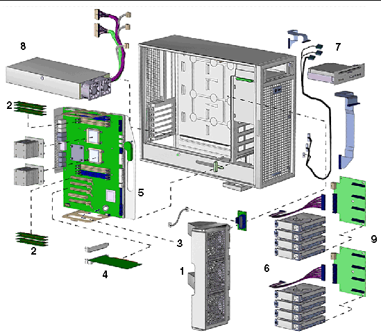
FIGURE 4-6 Ultra 40 M2 Major Workstation Components
|
Section 4.3, Preparing the Workstation for Servicing and
|
||
|
Section 4.3, Preparing the Workstation for Servicing and
|
||
|
Hard drive backplane and cables (filler panel is absent when second backplane is present) |
Section 6.2, Replacing the Hard Drive Backplane and Signal Cable |
|
|
The following components are not field-replaceable units: side cover and access panel. |
||
| Note - You do not need to remove the fan tray if you are replacing any of the following components: DIMMs, battery, PCI cards, or hard drives. |
Copyright © 2008, Sun Microsystems, Inc. All Rights Reserved.