| Skip Navigation Links | |
| Exit Print View | |

|
Sun Fire X4800 Server Service Manual |
About This Documentation (PDF and HTML)
Sun Fire X4800 Server Service Manual Overview
Sun Fire X4800 Server Overview
Sun Fire X4800 Server Chassis Overview
Sun Fire X4800 Server CPU Module (CMOD) and Filler Module Overview
Controlling Server Power Remotely
Removing and Installing Components
Preparing for Service and Operation
Removal and Installation Procedures
Removing and Installing a Power Supply (CRU)
Removing and Installing a Hard Drive (CRU)
Removing and Installing a Hard Drive Filler
Replacing the Hard Drive Backplane (FRU)
Adding, Removing, and Installing a CMOD (CRU)
CPU Module (CMOD) Designation and Population Rules
Removing and Installing a CMOD Filler
How to Replace the CMOD Battery (CRU)
Removing and Installing DIMMs (CRU)
Removing and Installing a RAID Expansion Module (CRU)
How to Replace the RAID Expansion Module Battery (CRU)
Removing and Installing a Fabric Expansion Module (CRU)
Replacing a CPU and Heatsink Assembly (FRU)
Removing and Installing a Fan Module (CRU)
Replacing a Fan Module Controller Board (FRU)
Removing and Installing a NEM or a NEM Filler (CRU)
Removing and Installing a PCIe EM (CRU)
Removing and Installing the Service Processor Module (CRU)
Removing and Installing the Multi port Cable
Removing and Installing the Subassembly Module (FRU)
Sun Fire X4800 Server Service Procedures, and Information
Firmware Information and Procedures
How to Access the BIOS Setup Utility
Component LED Locations and Meanings
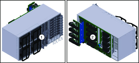
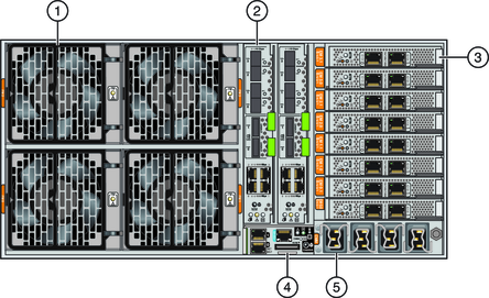
The Subassembly module (SAM) resides inside the chassis and contains the midplane on the internal front-facing side of the SAM and the back side server components on the back side of the SAM.

| ||||||||
The SAM provides the interconnect between the AC power input lines and the power supply. It also provides the midplane interconnect between the back-end components (EMs, NEMs, and SP) and the front-side components (hard drives and CPU modules). Additionally, the SAM contains the cooling system for the CPU modules (CMODs). Cooling to the EMs, NEMs, and the SP module is provided by the power supply fans.
Note - The SAM is designated as a field-replaceable unit (FRU).

|
See also: