JavaScript is required to for searching.
Skip Navigation Links
Exit Print View
Sun Fire X4800 Server Product Documentation
search filter icon
search icon

Document Information

Using This Documentation

Hardware Installation

Installing the Server In the Rack Using the Standard Rack Mounting Kit

Tools and Staff Required

Installing Optional Equipment

Compatible Racks

Contents of the Standard Rack Mounting Kit

Location of the Rack Mounting Kit and the Shipping Bracket Kit

Installing the Server In a Rack Using the Standard Rack Mounting Kit

How to Remove Components to Reduce Weight

How to Replace the Components in the Server

How to Install the Rack Mounting Hardware in Standard Rack

How to Insert the Server Into the Rack

Removing and Installing the Standard Rack Mounting Kit Shipping Brackets

How to Remove the Standard Rack Mounting Kit Shipping Brackets

How to Install the Standard Rack Mounting Kit Shipping Brackets

Operating System Installation

Administration, Diagnostics, and Service

Index

How to Install the Standard Rack Mounting Kit Shipping Brackets

This procedure describes how to install brackets into a system equipped with the standard rack mounting kit.

The shipping bracket kit contains the following parts:
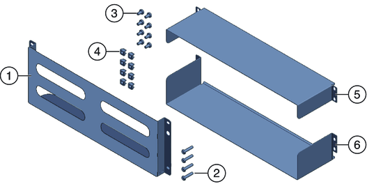
image:Contents of shipping bracket kit.
Figure Legend
1
Front shipping bracket
2, 3
Two sets of screws (M6 and 10-32). Each set contains four screws for the front shipping bracket (2) and eight screws for the rear shipping brackets (5 and 6)
4
Eight M6 cage nuts for rear shipping bracket in square-hole racks
5
Top rear shipping bracket
6
Bottom rear shipping bracket

Note - The shipping bracket kit is shipped in the accessory tray with the rack mounting kit. See Location of the Rack Mounting Kit and the Shipping Bracket Kit for details.
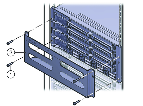

  1. Remove the four (short) screws that fasten the front of the server to the rack.
  2. Insert the front shipping bracket (1) into the front of the server with the supporting flange underneath the server.
  3. The front shipping bracket contains eight threaded holes used for storing unused screws (four M6 and four 10–32). Remove the long screws that match the threads on your rack.
  4. Use the four long screws (M6 or 10–32) (1) to fasten the shipping bracket (2) to the front of the server.
    image:Front shipping bracket and screws.
  5. Insert the short screws into the four empty storage holes on the shipping bracket.

    They will be stored there to be used when you remove the shipping bracket.

  6. If you are installing the shipping brackets in a rack with square holes, check to ensure that the cage nuts are installed in the rear.

    Note the orientation and location of the cage nuts for the shipping bracket.

    • There are four cage nuts per side (eight total).

    • They are installed on the inside of the rack, facing outward. This is the opposite direction from the cage nuts for the shelf adapter brackets.

    • For each shipping bracket, there should be two shipping bracket cage nuts; one in the hole directly above the shipping bracket cage nut, and one in the third hole above the shipping bracket cage nut.

    If the cage nuts are not in place, you must:

    1. Remove the server and the mounting hardware from the rack, as described in Removing the Server From the Rack.
    2. Reinstall the adapter brackets and the server, and install the rear shipping bracket cage nuts as you install the rear adapter brackets. This is included in the rack mounting procedure.

      See How to Install the Rack Mounting Hardware in Standard Rack.

  7. Insert the rear top shipping bracket (1) over the back of the server with the side panels facing down.

    Use four screws (2) to fasten it to the rack (4).

  8. Insert the rear bottom shipping bracket (3) under the back of the server with the side panels facing up.

    Use four screws (4) to fasten it to the rack.
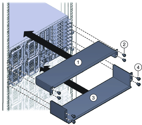

    image:Rear shipping brackets