Example Configuration
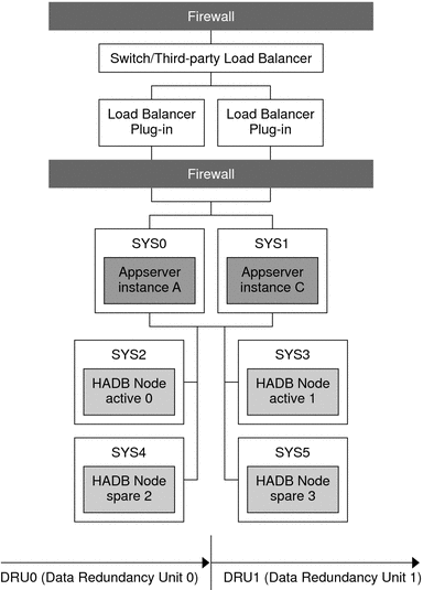
The following figure illustrates the separate tier topology.
Figure 3–3 Example Separate Tier Topology

In this topology, machine SYS0 hosts Application Server instance A and machine SYS1 hosts Application Server instance B. These two instances form a cluster that persists session information to the two DRUs:
-
DRU0 comprises two machines, SYS2 and SYS4. HADB node active 0 is on machine SYS2 and the HADB node spare 2 is on machine SYS4.
-
DRU1 comprises two machines, SYS3 and SYS5. HADB node active 1 is on machine SYS3 and the HADB node spare 3 on machine SYS5.
All the nodes on a DRU are on different machines, so that even if one machine fails, the complete data for any DRU continues to be available on other machines.
- © 2010, Oracle Corporation and/or its affiliates
