| C H A P T E R 4 |
|
Shelf Management Card Description |
The Netra CT 900 server has two dedicated slots for the shelf management cards. Each shelf management card is a 78 mm by 280 mm form factor board with a SODIMM socket for the shelf management mezzanine (ShMM) device. The Netra CT 900 server has IPMBs and is designed to work with two redundant shelf management cards. The shelf management card also contains the fan controller for the three hot-swappable fan trays, and provides individual Ethernet connections to both switches.
The dual-IPMB interface from the ShMM is connected to the dual IPMBs on an ATCA node board through radial connections in the Netra CT 900 server midplane. Each shelf management card has an Ethernet port that is not available to the user; instead, Ethernet traffic from the shelf management card is routed to the Ethernet ports on the switches. Serial and telco alarm traffic from the shelf management card are routed to the ports and LEDs on the shelf alarm panel.
The shelf management card includes several on-board devices that enable different aspects of shelf management based on the ShMM. These facilities include I2C-based hardware monitoring and control and General Purpose Input/Output (GPIO) expander devices.
FIGURE 4-1 shows a shelf management card.
This chapter contains the following topics:
FIGURE 4-1 Shelf Management Card
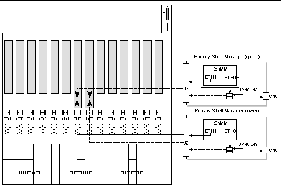
Each shelf management card provides two 10/100 Ethernet interfaces. The first Ethernet channel (ETH0) is routed to the J2 connector on the Netra CT 900 server midplane. The Netra CT 900 server midplane routes ETH0 from the J2 connector to the shelf management card port on the corresponding switch. The second Ethernet channel (ETH1) is routed to the other switch.
Both Ethernet ports support 10-Mb (10BASE-T) and 100-Mb (100BASE-TX) connections. The shelf management card also provides status LEDs for the two Ethernet channels. Refer to Chapter 5 for more information on the switch, and Ports and LEDs for more information on the Ethernet LEDs.
FIGURE 4-2 shows the connections of the Ethernet channels in the Netra CT 900 server.
| Note - Do not use the Ethernet ports at the front of the shelf management cards. |

FIGURE 4-2 Ethernet Connections in the Netra CT 900 Server
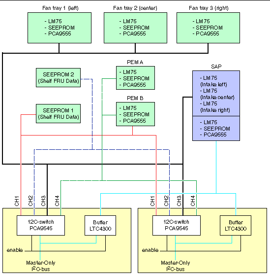
The master-only I2C bus is used internally on the shelf management card for the rear transition module and SEEPROM devices. The shelf management card also has a number of on-board I2C devices connected to the master-only I2C bus. These devices read the slot hardware address, exchange the hardware status with the backup shelf management card, and communicate with the system management controller ADM1026.
The master-only I2C bus is fed to a 4-channel switch (PCA9545) and then routed through the J2 midplane connector to:
The master only I2C-bus is buffered by a LTC4300 device and is then routed to the shelf alarm panel. The Active signal of the shelf management card is used to enable the I2C switch and the LTC4300 buffer so that only the active shelf management card has access to the shelf I2C-bus devices.

FIGURE 4-3 Distribution of the Master-Only I2C Bus on the Midplane
The following sections give information on the ports and LEDs on the shelf management card.
The shelf management card provides an RS-232 console interface that provides a full set of the RS-232 signals, including modem control. These signals are routed to the serial port on the shelf alarm panel. Refer to Chapter 3 for more information on the serial ports on the shelf alarm panel for the primary and backup shelf management cards.
Following is the default configuration for the serial console:
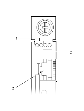
The shelf management card provides two status LEDs for the two Ethernet channels (ETH0 and ETH1). FIGURE 4-4 shows the location of the Ethernet LEDs on the shelf management card for both Ethernet channels.
The LEDs for the two Ethernet channels are:

FIGURE 4-4 Ethernet LEDs on the Shelf Management Card
The shelf management card provides a front panel Reset push button. If there is a hardware or software failure, the backup shelf management card takes over the shelf management functions. Use the front panel Reset push button to reset the failed shelf management card. If the reset successfully clears the hardware or software problem, the reset shelf management card becomes the active shelf management card once again and resumes the shelf management functions.
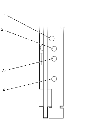
FIGURE 4-5 shows the location of the front panel Reset push button.

FIGURE 4-5 Status and Hot-Swap LEDs and Reset Button on the Shelf Management Card
There are two Status LEDs on the shelf management card: the green (upper) Status LED and the red (lower) Status LED. The Status LEDs tell you whether that particular shelf management card is the active or backup card, and if the card is running or not.
The shelf management card provides a blue Hot-Swap LED. This LED indicates when it is safe to remove the shelf management card from a shelf that is powered on. TABLE 4-4 describes the different states for the Hot-Swap LED.
|
The shelf management card is not ready to be removed or disconnected from the shelf. |
|
|
The shelf management card is ready to be removed or disconnected from the shelf. |
|
The shelf management card reads the hardware address and parity bit from the midplane connector of the dedicated shelf management card slot.
The shelf management card supports redundant operation with automatic switchover using redundant shelf management cards. In a configuration where two shelf management cards are present, the upper shelf management card acts as the active shelf management card and the lower shelf management card acts as a backup. The shelf management cards monitor each other and either can trigger a switchover if necessary.
Copyright © 2009 Sun Microsystems, Inc. All rights reserved.