| C H A P T E R 2 |
|
Installing the Shelf |
This chapter describes the steps necessary to install and set up the Sun Netra CT 900 server (also referred to as the “shelf”). It includes instructions on unpacking, rackmounting, and making power connections.
This chapter includes the following topics:
Two versions of the Sun Netra CT 900 server are available: a 1GbE and a 10GbE version. For systems configured with Sun Netra CP3240 switches functioning as 10GbE switches, the 10GbE server is required.
You will need the following tools to install, remove, or replace most of the components in a Sun Netra CT 900 server:
Check the shipping carton for damage. If the shipping carton and contents are damaged, notify the carrier and Sun Microsystems for an insurance settlement. Retain the shipping carton and packing material for inspection by the carrier. Obtain authorization before returning any product to Sun Microsystems. Contact your local Sun Microsystems sales representative for more information.
Following are the instructions for unpacking the Sun Netra CT 900 server:
1. Remove the straps that secure the box to the pallet.
2. Lift the top outer box straight up and away from the remaining packing materials.
3. Go to the rear of the Sun Netra CT 900 server and remove the cardboard divider from the box.
4. Remove the foam piece from the top of the Sun Netra CT 900 server.
5. Go to the front of the Sun Netra CT 900 server and lower the flap on the bottom piece of the box by pulling it down and away from the server.
6. Remove the foam packing material from the bottom front of the server.

|
Caution - The edges at the bottom of the Sun Netra CT 900 server may be very sharp. Use extreme caution when lifting the Sun Netra CT 900 server from the bottom. |
7. Position the mechanical lift in the area beneath the middle fan tray, then lift the server up and out of the box.

|
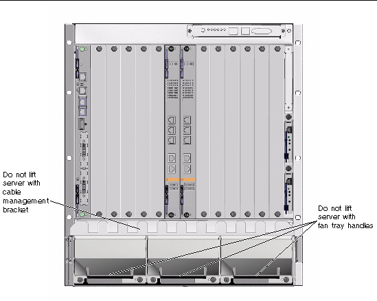
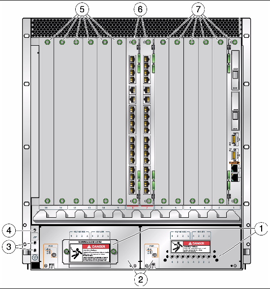
Caution - Do not use the fan tray handles or the cable management brackets as lifting points. Refer to FIGURE 2-1for the location of the fan tray handles and the cable management brackets. |
FIGURE 2-1 Sun Netra CT 900 Server (Front)
The Sun Netra CT 900 server is shipped fully assembled and tested. The baseline configuration and most common options are listed in the following section. Your system might differ from the system described in this manual.
Following are the features of the Sun Netra CT 900 server:
FIGURE 2-2 shows the components in a Sun Netra CT 900 server 1GbE chassis from the front, and FIGURE 2-3 shows the components in a Sun Netra CT 900 server 1GbE chassis from the back. To use the next generation node boards and advanced rear transition modules in the 1GbE chassis, fan trays must be upgraded to provide adequate cooling. (Refer to the Sun Netra CT 900 Server Upgrade Guide, 820-3255).
FIGURE 2-4 shows the components in a Sun Netra CT 900 server 10GbE version from the front, and FIGURE 2-5 shows the components in a Sun Netra CT 900 server 10GbE version from the back. This chassis is designed for the next generation of switches, node boards, and advanced rear transition modules.
In addition to the basic configuration, the 10GbE chassis has the following features, which support 10GbE switching, next generation node boards, and advanced rear transition modules (ARTMs).
FIGURE 2-2 Sun Netra CT 900 Server 1GbE Chassis Components (Front View)
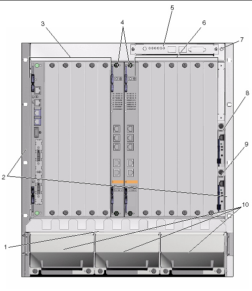
FIGURE 2-3 Sun Netra CT 900 Server 1GbE Chassis Components (Back View)
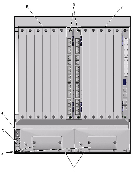
FIGURE 2-4 Sun Netra CT 900 Server 10GbE Chassis Components (Front View)
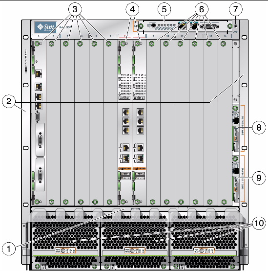
FIGURE 2-5 Sun Netra CT 900 Server 10GbE Chassis Components (Back View)
| Note - Static electricity can harm delicate components inside the Sun Netra CT 900 server. To protect system components from static shock when handling them, wear a wrist strap plugged into an ESD ground jack. ESD ground jacks are located at the front and rear of the system. See FIGURE 2-2 and FIGURE 2-3 for the location of the ESD ground jacks. The ESD ground jacks will provide adequate static protection only if the server is grounded to a building ground, the server is installed in a grounded rack, or the server is sitting on a properly installed static mat. |
Before installing and using the Sun Netra CT 900 server, ensure that all cover panels are in place and that all component slots are populated with a component or covered with a blank filler panel.

|
Caution - Failure to cover open slots could cause overheating of boards or other components, and could damage the system. |

|
Caution - The edges at the bottom of the Sun Netra CT 900 server may be very sharp. Use extreme caution when lifting the Sun Netra CT 900 server from the bottom. |
Be sure to mount the system in a way that ensures even weight distribution in the rack. Uneven mechanical loading can result in a hazardous condition. Secure all mounting bolts when installing the enclosure to the frame or rack.
Install the system in an environment compatible with the recommended maximum ambient temperature. Due to the modular design of the system, components might be installed that alter the system’s operating requirements. Refer to the system specifications in the Sun Netra CT 900 Server Service Manual for the maximum recommended ambient temperature for the Sun Netra CT 900 server, and to product-specific documentation for the maximum recommended ambient temperature for individual components.
Use TABLE 2-1 and FIGURE 2-6 to determine the rackmount kit for your chassis.
|
Note: Uses front flange for mounting and 10-32 chassis bottom inserts. Bottom and slide mounting are available for customer integration. |
|||||
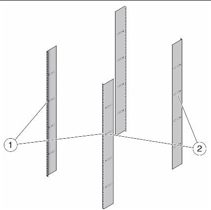
FIGURE 2-6 Front Mounting and Side Mounting Options
|
Front mounting (parallel to the front rails): The screws that attach the shelf to the rack are installed from the front of the rack. |
|
|
Side mounting (parallel to the side rails): The screws that attach the shelf to the rack are installed from the side of the rack. |
1. Disconnect all power sources, external connections, and cables prior to installing the system into a rack.
2. Remove the rackmount tray from the ship kit.
3. Select a position in the rack that does not interfere with other equipment and that provides safe weight distribution.
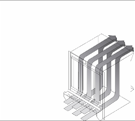
Ensure that the area around the Sun Netra CT 900 server’s intake and exhaust vents will be clear of obstructions for efficient cooling. FIGURE 2-7 shows the proper airflow for the Sun Netra CT 900 server.
4. Go to the appropriate rackmount installation instructions for the your rackmount kit.
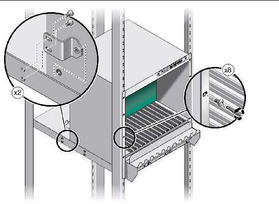
1. Place the rackmount tray in its intended location and bolt the tray to the front and rear of the rack using eight M5 screws (FIGURE 2-8).
FIGURE 2-8 Mounting the Rackmount Tray Using Rackmount Kit X4023A
2. Using the mechanical lift, place the Sun Netra CT 900 server on the tray.
3. Bolt the front left and right flanges of the ATCA shelf with eight screws to the front columns (FIGURE 2-9).
| Note - Rack hardware is not included. |
4. Insert the locating bushings of the rear mounting brackets into the holes at the rear lower side of the ATCA shelf (FIGURE 2-9).
5. Bolt the rear mounting brackets with M6 screws to the rackmount tray (FIGURE 2-9).
FIGURE 2-9 Installing the ATCA Shelf in the Rack Using Rackmount Kit X4023A
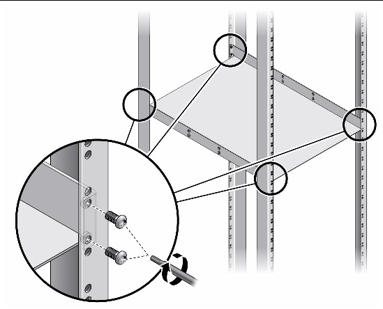
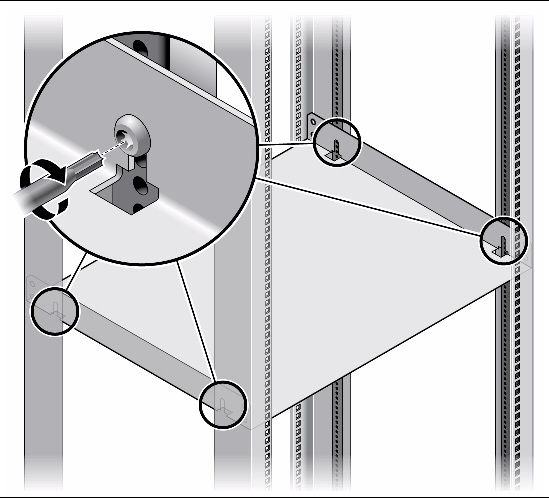
1. Place the rackmount tray in its intended location and bolt the tray with four thread-forming screws to the front and rear columns of the rack (FIGURE 2-10).
FIGURE 2-10 Mounting the Rackmount Tray Into the Rack Using Rackmount Kit X4022A
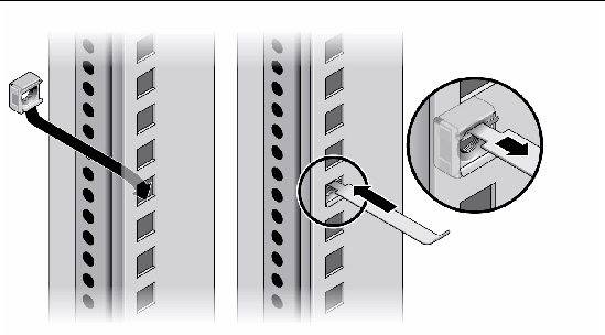
2. Determine the mounting holes for the M6 cage nuts in the front columns.
3. Attach four M6 cage nuts to each front rack column using the insertion tool (FIGURE 2-11).
FIGURE 2-11 Attaching the Cage Nuts for the Rackmount Kit X4022A.
4. Using the mechanical lift, place the Sun Netra CT 900 server on the rackmount tray.
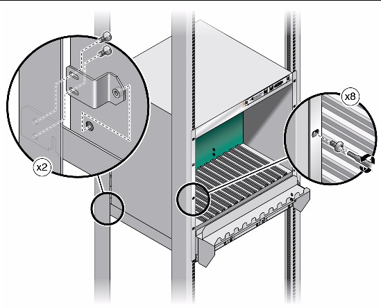
5. Insert the locating bushings of the rear mounting brackets into the holes at the rear lower side of the ATCA shelf (FIGURE 2-12).
6. Bolt the front mounting brackets of the ATCA shelf with eight M6 screws to the front columns (FIGURE 2-12).
FIGURE 2-12 Installing the ATCA Shelf in the Rack Using the Rackmount Kit X4022A
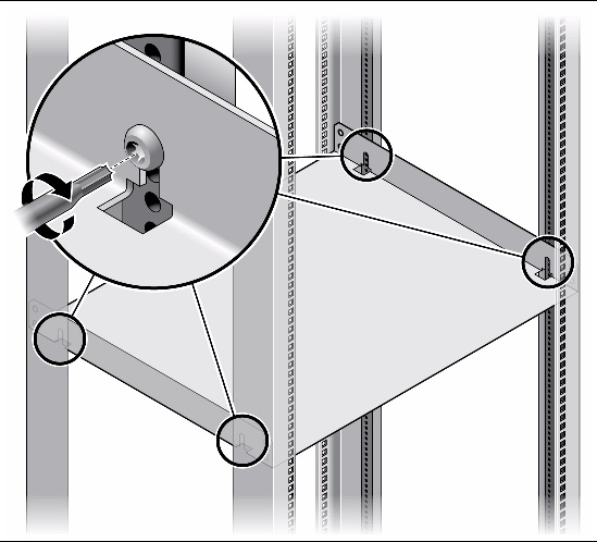
1. Place the rackmount tray in its intended location and bolt the tray with four thread-forming screws to the front and rear columns of the rack (FIGURE 2-13).
FIGURE 2-13 Mounting the Rackmount Tray Into the Rack Using Rackmount Kit X4023A
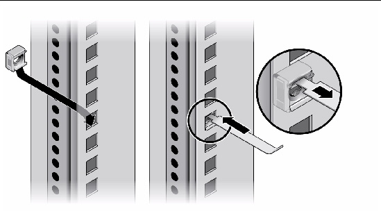
2. Determine the mounting holes for the M6 cage nuts in the front columns.
3. Attach four M6 cage nuts to each front rack column using the insertion tool (FIGURE 2-14).
FIGURE 2-14 Attaching the Cage Nuts for the Rackmount Kit X4023A.
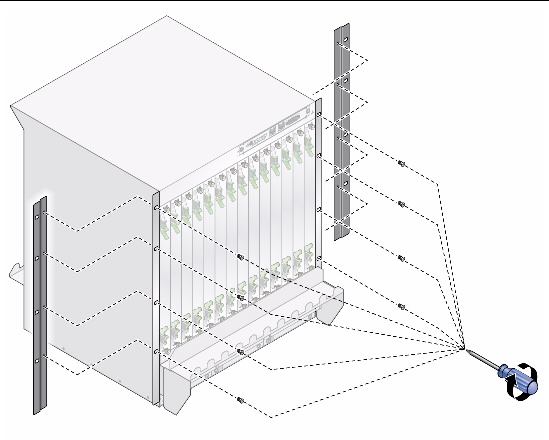
4. Using the mechanical lift, place the Sun Netra CT 900 server on the rackmount tray.
5. Bolt the extension flange to the front mounting brackets of the ATCA shelf with eight M6 screws, 4 screws on each side (FIGURE 2-15).
6. Bolt the extension flanges on the ATCA shelf to the front columns with eight M6 screws, 4 screws on each side.
FIGURE 2-15 Installing the ATCA Shelf in the Rack Using the Rackmount Kit X4023A
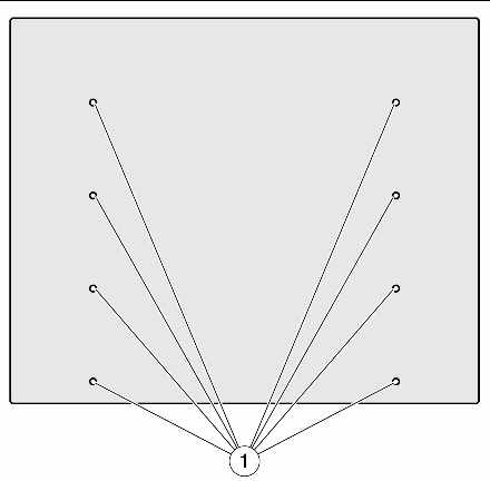
Bottom shelf slide mounts can be used for sliding the Sun Netra CT 900 server in and out of the bottom shelf of the rack. There are no rackmount kits available for this type of mounting but threaded inserts are provided on the bottom of the chassis. These mounting points can be used for attaching U-channels that are capable of supporting the server. The threaded mounting points as shown in (FIGURE 2-16.)
FIGURE 2-16 Mounting Points on Bottom of Chassis for Slide-Mount Installation
You can remove the front cable management bracket if you find that the bracket interferes with the front doors on the rack.
1. Go to the front of the Sun Netra CT 900 server and locate the front cable management bracket.
2. Using the 7mm socket wrench, remove the four nuts (two on each side) that secure the front cable management bracket to the Sun Netra CT 900 server (FIGURE 2-17).
FIGURE 2-17 Removing the Front Cable Management Bracket
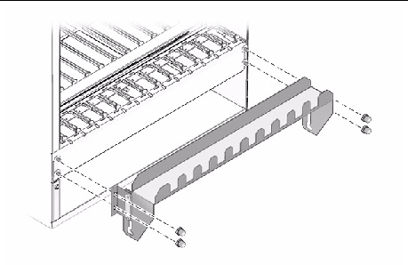
3. Remove the front cable management bracket from the Sun Netra CT 900 server and store it in a safe place.
In a typical telco environment, the VRTN path of the -48V supply is grounded to the protective earth (PE) of the building.
Following are the specifications for the DC grounding cable:

|
Caution - The shelf is intended to be grounded. Make sure that the DC grounding lugs are connected to the protective earth (PE) of the building before powering up the shelf. |
1. Get a DC grounding cable and two M5 nuts with star washers.
2. Go to the back of the chassis and locate the two DC grounding lugs (FIGURE 2-18).
FIGURE 2-18 Locating the DC Grounding Lugs
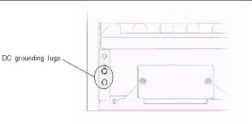
3. Remove the plastic shielding from the DC grounding lugs.
4. Align the DC grounding cable against the two DC grounding lugs at the rear of the chassis.
5. Place the star washers between the DC grounding cable and the two M5 nuts that you will use to secure one end of the grounding cable to the two lugs.
6. Tighten the two M5 nuts to secure the grounding cable to the two lugs.
7. Secure the other end of the grounding cable to the earth ground in the building.
You can secure the grounding cable to a proper grounding point on the rack, as long as the rack is properly grounded to the earth ground in the building.
The power input panel configuration must match the voltage input configuration of the power entry modules intended for use with the system.
The Sun Netra CT 900 server must be connected to properly rated supplies. For permanently connected equipment, a readily accessible disconnect device should be incorporated in the building wiring installation. Circuit breakers should be rated to handle the current indicated in the input specifications listed on the product identification label at the rear of the Sun Netra CT 900 server.
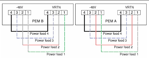
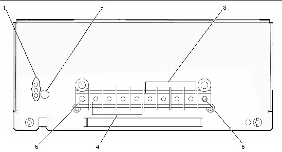
Each power entry module has four power feeds going into the system. FIGURE 2-19 shows the proper connections for the -48V and VRTN power going into the four feeds for each power entry module.
Refer to the Sun Netra CT 900 Server Product Overview for more information about how power is distributed through the Sun Netra CT 900 server and how to calculate power requirements.

|
Caution - Always ensure that the system is properly grounded before applying power. When the system is plugged in, energy hazards are present on the midplane. Do not reach into the enclosure. |
FIGURE 2-19 Power Feeds Going Into the Power Entry Modules

|
Caution - Before working on the Sun Netra CT 900 server, you must disconnect power from the DC power sources. When the Sun Netra CT 900 server is powered on, do not touch the power terminals. |
1. Disconnect power from the DC power sources.
2. Go to the rear of the shelf and loosen the two captive thumbscrews that secure the terminal block cover over each power entry module (FIGURE 2-20).
FIGURE 2-20 Location of the Captive Thumbscrews
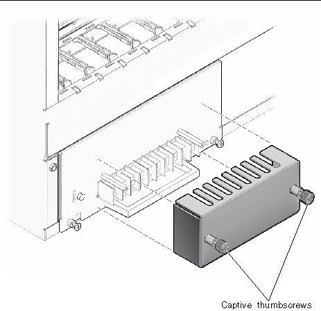
3. Remove the terminal block covers from the rear of the shelf.
4. Attach the cables to the appropriate terminal posts on each power entry module (FIGURE 2-21).
Keep the following restrictions in mind when connecting the DC power source to the Sun Netra CT 900 server:
FIGURE 2-21 Power Entry Module Terminal Posts
5. Replace the terminal block covers on the power entry modules.
Make sure the terminal block cover is placed above the handle on each power entry module.
6. Complete the connection to the DC power source.
When power is first applied to the shelf, the following events occur:
As the shelf management card boots, the following events occur:

|
Caution - Before working on the shelf, disconnect power from the DC power sources. When the shelf is powered on, do not touch the power entry module terminal posts. |
Copyright © 2010, Oracle and/or its affiliates. All rights reserved.