Overview of VLAN Topology
Switched LAN technology enables you to organize the systems on a local network into VLANs. Before you can divide a local network into VLANs, you must obtain switches that support VLAN technology. You can configure all ports on a switch to serve a single VLAN or multiple VLANs, depending on the VLAN topology design. Each switch manufacturer has different procedures for configuring the ports of a switch.
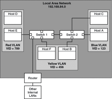
The following figure shows a local area network that has the subnet address 192.168.84.0. This LAN is subdivided into three VLANs, Red, Yellow, and Blue.
Figure 6–1 Local Area Network With Three VLANs

Connectivity on LAN 192.168.84.0 is handled by Switches 1 and 2. The Red VLAN contains systems in the Accounting workgroup. The Human Resources workgroup's systems are on the Yellow VLAN. Systems of the Information Technologies workgroup are assigned to the Blue VLAN.
VLAN Tags and Physical Points of Attachment
Each VLAN in a local area network is identified by a VLAN tag, or VLAN ID (VID). The VID is assigned during VLAN configuration. The VID is a 12-bit identifier between 1 and 4094 that provides a unique identity for each VLAN. In Figure 6–1, the Red VLAN has the VID 789, the Yellow VLAN has the VID 456, and the Blue VLAN has the VID 123.
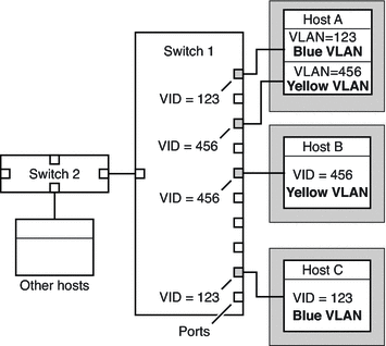
When you configure switches to support VLANs, you need to assign a VID to each port. The VID on the port must be the same as the VID assigned to the interface that connects to the port, as shown in the following figure.
Figure 6–2 Switch Configuration for a Network with VLANs

Figure 6–2 shows multiple hosts that are connected to different VLANs. Two hosts belong to the same VLAN. In this figure, the primary network interfaces of the three hosts connect to Switch 1. Host A is a member of the Blue VLAN. Therefore, Host A's interface is configured with the VID 123. This interface connects to Port 1 on Switch 1, which is then configured with the VID 123. Host B is a member of the Yellow VLAN with the VID 456. Host B's interface connects to Port 5 on Switch 1, which is configured with the VID 456. Finally, Host C's interface connects to Port 9 on Switch 1. The Blue VLAN is configured with the VID 123.
The figure also shows that a single host can also belong to more than one VLAN. For example, Host A has two VLANs configured over the host's interface. The second VLAN is configured with the VID 456 and is connected to Port 3 which is also configured with the VID 456. Thus, Host A is a member of both the Blue VLAN and the Yellow VLAN.
During VLAN configuration, you have to specify the physical point of attachment, or PPA, of the VLAN. You obtain the PPA value by using this formula:
driver-name + VID * 1000 + device-instance |
Note that the device-instance number must be less than 1000.
For example, you would create the following PPA for a ce1 interface to be configured as part of VLAN 456:
ce + 456 * 1000 + 1= ce456001 |
- © 2010, Oracle Corporation and/or its affiliates
